CH714987A2 - Valve arrangement and method for reducing virus migration through a virus removal filter after reducing the inflow. - Google Patents
Valve arrangement and method for reducing virus migration through a virus removal filter after reducing the inflow. Download PDFInfo
- Publication number
- CH714987A2 CH714987A2 CH5632019A CH5632019A CH714987A2 CH 714987 A2 CH714987 A2 CH 714987A2 CH 5632019 A CH5632019 A CH 5632019A CH 5632019 A CH5632019 A CH 5632019A CH 714987 A2 CH714987 A2 CH 714987A2
- Authority
- CH
- Switzerland
- Prior art keywords
- line
- recirculation
- inlet
- valve
- outlet
- Prior art date
Links
Classifications
-
- B—PERFORMING OPERATIONS; TRANSPORTING
- B01—PHYSICAL OR CHEMICAL PROCESSES OR APPARATUS IN GENERAL
- B01D—SEPARATION
- B01D35/00—Filtering devices having features not specifically covered by groups B01D24/00 - B01D33/00, or for applications not specifically covered by groups B01D24/00 - B01D33/00; Auxiliary devices for filtration; Filter housing constructions
- B01D35/14—Safety devices specially adapted for filtration; Devices for indicating clogging
- B01D35/157—Flow control valves: Damping or calibrated passages
- B01D35/1573—Flow control valves
-
- B—PERFORMING OPERATIONS; TRANSPORTING
- B01—PHYSICAL OR CHEMICAL PROCESSES OR APPARATUS IN GENERAL
- B01D—SEPARATION
- B01D61/00—Processes of separation using semi-permeable membranes, e.g. dialysis, osmosis or ultrafiltration; Apparatus, accessories or auxiliary operations specially adapted therefor
- B01D61/02—Reverse osmosis; Hyperfiltration ; Nanofiltration
- B01D61/10—Accessories; Auxiliary operations
-
- A—HUMAN NECESSITIES
- A61—MEDICAL OR VETERINARY SCIENCE; HYGIENE
- A61L—METHODS OR APPARATUS FOR STERILISING MATERIALS OR OBJECTS IN GENERAL; DISINFECTION, STERILISATION OR DEODORISATION OF AIR; CHEMICAL ASPECTS OF BANDAGES, DRESSINGS, ABSORBENT PADS OR SURGICAL ARTICLES; MATERIALS FOR BANDAGES, DRESSINGS, ABSORBENT PADS OR SURGICAL ARTICLES
- A61L2/00—Disinfection or sterilisation of materials or objects, in general; Accessories therefor
- A61L2/02—Disinfection or sterilisation of materials or objects, in general; Accessories therefor using physical processes
- A61L2/022—Filtration
-
- B—PERFORMING OPERATIONS; TRANSPORTING
- B01—PHYSICAL OR CHEMICAL PROCESSES OR APPARATUS IN GENERAL
- B01D—SEPARATION
- B01D37/00—Processes of filtration
- B01D37/04—Controlling the filtration
-
- B—PERFORMING OPERATIONS; TRANSPORTING
- B01—PHYSICAL OR CHEMICAL PROCESSES OR APPARATUS IN GENERAL
- B01D—SEPARATION
- B01D61/00—Processes of separation using semi-permeable membranes, e.g. dialysis, osmosis or ultrafiltration; Apparatus, accessories or auxiliary operations specially adapted therefor
- B01D61/02—Reverse osmosis; Hyperfiltration ; Nanofiltration
- B01D61/08—Apparatus therefor
-
- B—PERFORMING OPERATIONS; TRANSPORTING
- B01—PHYSICAL OR CHEMICAL PROCESSES OR APPARATUS IN GENERAL
- B01D—SEPARATION
- B01D61/00—Processes of separation using semi-permeable membranes, e.g. dialysis, osmosis or ultrafiltration; Apparatus, accessories or auxiliary operations specially adapted therefor
- B01D61/14—Ultrafiltration; Microfiltration
-
- B—PERFORMING OPERATIONS; TRANSPORTING
- B01—PHYSICAL OR CHEMICAL PROCESSES OR APPARATUS IN GENERAL
- B01D—SEPARATION
- B01D2311/00—Details relating to membrane separation process operations and control
- B01D2311/25—Recirculation, recycling or bypass, e.g. recirculation of concentrate into the feed
- B01D2311/251—Recirculation of permeate
- B01D2311/2512—Recirculation of permeate to feed side
-
- B—PERFORMING OPERATIONS; TRANSPORTING
- B01—PHYSICAL OR CHEMICAL PROCESSES OR APPARATUS IN GENERAL
- B01D—SEPARATION
- B01D2311/00—Details relating to membrane separation process operations and control
- B01D2311/25—Recirculation, recycling or bypass, e.g. recirculation of concentrate into the feed
- B01D2311/252—Recirculation of concentrate
- B01D2311/2523—Recirculation of concentrate to feed side
-
- B—PERFORMING OPERATIONS; TRANSPORTING
- B01—PHYSICAL OR CHEMICAL PROCESSES OR APPARATUS IN GENERAL
- B01D—SEPARATION
- B01D2313/00—Details relating to membrane modules or apparatus
- B01D2313/18—Specific valves
Landscapes
- Chemical & Material Sciences (AREA)
- Engineering & Computer Science (AREA)
- Water Supply & Treatment (AREA)
- Chemical Kinetics & Catalysis (AREA)
- Nanotechnology (AREA)
- Health & Medical Sciences (AREA)
- Epidemiology (AREA)
- Life Sciences & Earth Sciences (AREA)
- Animal Behavior & Ethology (AREA)
- General Health & Medical Sciences (AREA)
- Public Health (AREA)
- Veterinary Medicine (AREA)
- External Artificial Organs (AREA)
- Separation Using Semi-Permeable Membranes (AREA)
- Apparatus Associated With Microorganisms And Enzymes (AREA)
Abstract
Eine Ventilanordnung (100) zum Reduzieren der Migration eines oder mehrerer Viren durch einen Filter (110), wenn der Zuflussstrom zum Filter (110) nach einer Reduzierung des Zuflussstroms wieder aufgenommen wird, beinhaltet eine Einlassleitung (102) mit einer Einlassöffnung (104), die mit einer Produktzufuhr (127) zu verbinden ist, und einer Auslassöffnung (108), die mit einem Einlass (109) des Filters (110) zu verbinden ist, eine Pumpe (124), eine Auslassleitung (112) und ein Rezirkulationssystem (132). Das Rezirkulationssystem (132) beinhaltet eine Rezirkulationsleitung (130), die die Auslassleitung (112) und die Einlassleitung (102) verbindet, und ein Rückschlagventil (122), das entlang der Rezirkulationsleitung (130) angeordnet ist. Wenn das Rückschlagventil (122) die Reduzierung des Zuflusses erkennt, wird ein Rezirkulationskreislauf erstellt, so dass das Produkt (126) während der Reduzierung kontinuierlich durch den Filter (110) zurückgeführt wird, wodurch ein kontinuierlicher Fluidstrom durch den Filter (110) auch während der Reduzierung gewährleistet ist.A valve assembly (100) for reducing the migration of one or more viruses through a filter (110), when the inflow stream to the filter (110) is resumed after a reduction in the inflow stream, includes an inlet conduit (102) having an inlet port (104), which is to be connected to a product supply (127) and an outlet port (108) to be connected to an inlet (109) of the filter (110), a pump (124), an outlet conduit (112) and a recirculation system (132 ). The recirculation system (132) includes a recirculation line (130) connecting the outlet line (112) and the inlet line (102) and a check valve (122) disposed along the recirculation line (130). When the check valve (122) detects the reduction in the inflow, a recirculation loop is established so that the product (126) is continually returned through the filter (110) during the reduction, whereby a continuous flow of fluid through the filter (110) also during the Reduction is guaranteed.
Description
Beschreibungdescription
TECHNISCHES GEBIET DER ERFINDUNG [0001] Die vorliegende Offenbarung bezieht sich ganz allgemein auf Virenfiltersysteme und insbesondere auf ein System und Verfahren zur Sicherstellung eines kontinuierlichen Flusses durch einen Virusentfernungsfilter, um eine Virusmigration durch den Virusentfernungsfilter nach einer Reduzierung des Zuflusses zu verhindern.TECHNICAL FIELD OF THE INVENTION The present disclosure relates generally to virus filter systems and, more particularly, to a system and method for ensuring continuous flow through a virus removal filter to prevent virus migration through the virus removal filter after a reduction in inflow.
STAND DER TECHNIK [0002] Pharmazeutische Arzneimittel, die aus biologischen Quellen hergestellt, extrahiert oder synthetisiert werden, müssen Schritte zur Virusreduktion durchlaufen, um das Potenzial der viralen Kontamination im Arzneimittel selber zu verringern. Ebenso müssen Blutprodukte und Derivate Schritte zur Virusreduktion durchlaufen, um das Potenzial der viralen Kontamination im Produkt zu verringern. Eine dieser bekannten Methoden der Virusreduktion ist die Grössenausschlussfilterung. Durch die Grössenausschlussfilterung wird ein Zufluss, der das zu filternde Produkt enthält, durch einen Virusentfernungsfilter geleitet. Der Virusentfernungsfilter verfügt über eine Virusfiltrationsmembran, die die zu entfernenden Viren aus dem Produkt auffängt. Um das Virus einzufangen, wird die Membran so hergestellt, dass sie Millionen von Hohlräumen aufweist, die sich zu multiplen Kapillaren verbinden, die sich ihrerseits zu einem Gitter verbinden, durch das die Flüssigkeit hindurchtreten muss, um den Filter zu verlassen. Daher hat ein Virus, das in dem Flüssigkeitsstrom mitgerissen wird, einen verwundenen Weg, um einen Weg durch die Virusfiltermembran zu finden, um ihn zu verlassen. Auf diesem verwundenen oder qualvollen Weg kann ein Virus durch Grössenausschluss in oder um eine Kapillare eingeschlossen werden. Es kann auch durch Strömungskräfte oder Affinität zu einer Hohlraumwand in einem solchen Hohlraum gehalten werden. Um beispielsweise ein Virus mit einem Querschnittsdurchmesser von 17 Nanometern (»nm») einzufangen, müssen die Kapillaren einen Querschnittsdurchmesser von weniger als 17 nm irgendwo auf ihrer Länge aufweisen oder ein Hohlraum muss ein Virus mit einem Querschnittsdurchmesser von weniger als 17 Nanometern durch Strömungskräfte oder Affinität zu den Wänden des Hohlraums zurückhalten.BACKGROUND ART Pharmaceutical drugs that are made, extracted, or synthesized from biological sources must undergo virus reduction steps to reduce the potential for viral contamination in the drug itself. Blood products and derivatives must also go through virus reduction steps to reduce the potential for viral contamination in the product. One of these known methods of virus reduction is size exclusion filtering. By using size exclusion filtering, an inflow containing the product to be filtered is passed through a virus removal filter. The virus removal filter has a virus filtration membrane that collects the viruses to be removed from the product. To capture the virus, the membrane is made to have millions of cavities that connect to multiple capillaries, which in turn connect to a grid through which the liquid must pass to exit the filter. Therefore, a virus entrained in the fluid stream has a tortuous path to find a way through the virus filter membrane to exit. In this tortuous or tortuous path, a size exclusion virus can be trapped in or around a capillary. It can also be held in such a cavity by flow forces or affinity for a cavity wall. For example, to capture a virus with a cross-sectional diameter of 17 nanometers (»nm»), the capillaries must have a cross-sectional diameter of less than 17 nm anywhere along their length, or a cavity must have a virus with a cross-sectional diameter of less than 17 nanometers due to flow forces or affinity hold back to the walls of the cavity.
[0003] Eine Verringerung des Zuflusses durch den Virenentfernungsfilter kann aus verschiedenen Gründen während des Filtrationsprozesses auftreten. So kann beispielsweise eine Verringerung des Zuflusses durch den Virenentfernungsfilter als Folge einer Verringerung der Versorgung und Zulaufs des Filters auftreten. Alternativ oder zusätzlich kann eine Verringerung des Zuflusses oder Zulaufs durch den Virusentfernungsfilter als Folge von einer Ventilschaltung, einem Armaturenausfall, einem pneumatischem Ausfall, einem mechanischem Ausfall, einem elektrischem Ausfall und anderen absichtlichen oder nicht absichtlichen Handlungen oder Ereignissen auftreten. In jedem Fall wird durch eine solche Reduzierung des Zulaufs der Durchfluss durch den Virusentfernungsfilter reduziert oder sogar diskontinuierlich.A reduction in the inflow through the virus removal filter can occur during the filtration process for various reasons. For example, a reduction in the inflow through the virus removal filter can occur as a result of a reduction in the supply and inflow of the filter. Alternatively or additionally, a reduction in the inflow or inflow through the virus removal filter may occur as a result of valve switching, valve failure, pneumatic failure, mechanical failure, electrical failure and other intentional or unintentional actions or events. In any case, such a reduction in the inflow reduces the flow through the virus removal filter or even discontinuously.
[0004] Ein Virus, das durch Flüssigkeitsströmung oder Affinität zu den Wänden eines Hohlraums zurückgehalten wird, kann jedoch durch Brownsche Bewegung seinen Weg aus dem Rückhaltemedium finden, wenn der Flüssigkeitsstrom durch den Hohlraum reduziert wird (entweder teilweise oder vollständig). Mit anderen Worten, während des reduzierten Zulaufflusses kann sich ein Virus durch die Brownsche Bewegung um einen Hohlraum bewegen. Brownsche Bewegung kann ein Virus weit genug weg von dem Ort bewegen, an dem es in dem Hohlraum gehalten wurde, so dass, wenn der volle Zulauffluss durch den Hohlraum wieder aufgenommen wird, ein Virus in die Strömung mitgerissen wird und den Hohlraum in eine Kapillare oder einen anderen Hohlraum verlässt. Wenn ein Virus in den Fluss der Strömung mitgerissen wird und aus einem Hohlraum austritt, nachdem es einmal von diesem Hohlraum zurückgehalten wurde, hat es eine weitere Chance, durch die Virusfiltrationsmembran zu wandern, was die Chancen, dass das Virus den Virusentfernungsfilter vollständig durchläuft, unerwünscht erhöht.However, a virus retained by fluid flow or affinity for the walls of a cavity can find its way out of the retention medium through Brownian motion if the fluid flow through the cavity is reduced (either partially or completely). In other words, during the reduced inflow flow, a virus can move around a cavity through Brownian motion. Brownian motion can move a virus far enough away from where it was held in the cavity, so that when full inflow through the cavity is resumed, a virus is carried into the flow and the cavity into a capillary or leaves another cavity. If a virus is carried into the flow of the flow and emerges from a cavity once it has been retained by that cavity, it has another chance of migrating through the virus filtration membrane, which undesirably increases the chances of the virus completely passing through the virus removal filter elevated.
[0005] Ein reduzierter oder diskontinuierlicher Zuflussstrom durch einen Virenentfernungsfilter während des Filtrationsprozesses führt somit zu einer höheren Wahrscheinlichkeit, dass ein Virus durch den Virenentfernungsfilter wandert, wenn der volle Zuflussstrom wieder aufgenommen wird. Mit anderen Worten, die Reduzierung des Zuflussstroms durch einen Virusentfernungsfilter während des Filtrationsprozesses erhöht die Wahrscheinlichkeit, dass ein Virus seinen Weg durch den Virusentfernungsfilter findet, wenn der volle Zuflussstrom wieder aufgenommen wird. Es ist daher zu beachten, dass die Reduzierung des Zulaufs durch einen Virenentfernungsfilter während des Filtrationsprozesses ein Problem darstellt.A reduced or discontinuous inflow flow through a virus removal filter during the filtration process thus leads to a higher probability that a virus will migrate through the virus removal filter when the full inflow flow is resumed. In other words, reducing the inflow flow through a virus removal filter during the filtration process increases the likelihood that a virus will find its way through the virus removal filter when the full inflow flow is resumed. It should therefore be noted that reducing the inflow with a virus removal filter during the filtration process is a problem.
KURZE BESCHREIBUNG DER ZEICHNUNGEN [0006] Die als neu angesehenen Merkmale der vorliegenden Offenbarung sind besonders in den beigefugten Ansprüchen aufgeführt. Die vorliegende Offenbarung kann am besten unter Bezugnahme auf die folgende Beschreibung in Verbindung mit den beigefugten Zeichnungen verstanden werden, in der gleiche Bezugszeichen gleichartige Elemente in den einzelnen Figuren bezeichnen, in denen:BRIEF DESCRIPTION OF THE DRAWINGS The features of the present disclosure that are considered novel are set forth particularly in the appended claims. The present disclosure can best be understood with reference to the following description in conjunction with the accompanying drawings, in which like reference numerals designate like elements in the individual figures, in which:
Fig. 1 ist eine schematische Darstellung eines Beispiels einer Ventilanordnung, die gemäss den Lehren der vorliegenden Offenbarung konstruiert wurde, um die Migration eines oder mehrerer Viren über eine Virenentfernungsmembran zu reduzieren, wenn der volle Zulauf nach einer Reduzierung des Zulaufs wieder aufgenommen wird;1 is a schematic illustration of an example of a valve assembly constructed in accordance with the teachings of the present disclosure to reduce the migration of one or more viruses across a virus removal membrane when the full flow is resumed after the flow has been reduced;
CH 714 987 A2CH 714 987 A2
Fig. 2 ist eine schematische Darstellung eines weiteren Beispiels einer Ventilanordnung, die gemäss den Lehren der vorliegenden Offenbarung konstruiert wurde, um die Migration eines oder mehrerer Viren über eine Virenentfernungsmembran zu reduzieren, wenn der volle Zulauf nach einer Reduzierung des Zulaufs wieder aufgenommen wird;FIG. 2 is a schematic illustration of another example of a valve assembly constructed in accordance with the teachings of the present disclosure to reduce migration of one or more viruses across a virus removal membrane when the full supply is resumed after the supply has been reduced;
Fig. 3 ist eine schematische Darstellung eines weiteren Beispiels einer Ventilanordnung, die gemäss den Lehren der vorliegenden Offenbarung konstruiert wurde, um die Migration eines oder mehrerer Viren über eine Virenentfernungsmembran zu reduzieren, wenn der volle Zulauf nach einer Reduzierung des Zulaufs wieder aufgenommen wird.3 is a schematic illustration of another example of a valve assembly constructed in accordance with the teachings of the present disclosure to reduce migration of one or more viruses across a virus removal membrane when full flow is resumed after the flow has been reduced.
DETAILLIERTE BESCHREIBUNG [0007] Die vorliegende Offenbarung ist ganz allgemein auf eine Ventilanordnung gerichtet, um die Migration eines oder mehrerer Viren durch einen Virenentfernungsfilter zu reduzieren, wenn der Zuflussstrom nach einer Reduzierung des Zuflussstroms durch den Virenentfernungsfilter wieder aufgenommen wird. Die hier offenbarte Ventilanordnung reduziert die Migration eines oder mehrerer Viren, indem sie sicherstellt, dass ein kontinuierlicher Fluidstrom durch den Virenentfernungsfilter bereitgestellt wird, falls eine Verringerung des Zuflussstroms durch den Virenentfernungsfilter eintritt. In einigen Beispielen zirkuliert die Ventilanordnung Flüssigkeit vom Ausgang des Virusentfernungsfilters zum Eingang des Virusentfernungsfilters. Gleichzeitig ist die Ventilanordnung so konfiguriert, um zu verhindern, dass Viren in der Flüssigkeit, die zum Eingang des Virusentfernungsfilters strömt, in die Ausgangsflüssigkeit diffundieren können. In einigen Beispielen liefert die Ventilanordnung nach Beendigung der Zuflussstromreduzierung und Wiederaufnahme des vollen Zuflussstroms automatisch einen Rezirkulationspuffer, um das Herauskehren von in der Rezirkulationsleitung eingeschlossenem Fluid zu erleichtern.DETAILED DESCRIPTION The present disclosure is generally directed to a valve assembly to reduce migration of one or more viruses through a virus removal filter when the inflow flow is resumed after the inflow flow through the virus removal filter has been reduced. The valve arrangement disclosed herein reduces migration of one or more viruses by ensuring that a continuous fluid flow is provided through the virus removal filter in the event of a decrease in the inflow flow through the virus removal filter. In some examples, the valve assembly circulates fluid from the virus removal filter outlet to the virus removal filter inlet. At the same time, the valve arrangement is configured to prevent viruses in the liquid flowing to the entrance of the virus removal filter from diffusing into the starting liquid. In some examples, the valve assembly automatically provides a recirculation buffer upon completion of the inflow flow reduction and resumption of full inflow flow to facilitate the escape of fluid trapped in the recirculation line.
[0008] Fig. 1 zeigt ein Beispiel für ein System 100 zur Reduzierung der Migration eines oder mehrerer Viren über und durch einen Virenentfernungsfilter 110, wenn der Zuflussstrom wieder aufgenommen wird, nachdem eine Reduzierung des Zuflussstroms durch den Virusbeseitigungsfilter 110 erfolgt ist. Der Virenentfernungsfilter 110 weist eine Virusfiltrationsmembran auf, die allgemein gesehen konfiguriert ist, um die Virusreduktion aus einem Produkt 126 (z.B. einem in Lösung befindlichen pharmazeutischen Arzneimittel) durch Grössenausschluss zu bewirken, wenn das Produkt durch diese hindurchfliesst, indem sichergestellt wird, dass der Flüssigkeitsstrom durch den Virusfilter 110 kontinuierlich ist, so dass Viren nicht verdrängt und durch die Membran des Virusfilters 110 geleitet werden, sondern kontinuierlich und konsequent in der Membran des Virusfilters 110 eingeschlossen werden. Der Virenfilter 110 wird vorzugsweise aus regeneriertem Zelluloid hergestellt, z.B. von Asahi KASEI Medical Co. LTD, obwohl der Virenfilter 110 stattdessen aus Polysulfon oder Polyvinylidenfluorid hergestellt werden kann.Figure 1 shows an example of a system 100 for reducing the migration of one or more viruses over and through a virus removal filter 110 when the inflow flow is resumed after the inflow flow has been reduced by the virus removal filter 110. Virus removal filter 110 includes a virus filtration membrane that is generally configured to size exclude virus from a product 126 (e.g., a pharmaceutical drug in solution) when the product flows through it by ensuring that the fluid flow through the virus filter 110 is continuous, so that viruses are not displaced and passed through the membrane of the virus filter 110, but are continuously and consistently enclosed in the membrane of the virus filter 110. Virus filter 110 is preferably made from regenerated celluloid, e.g. from Asahi KASEI Medical Co. LTD, although virus filter 110 can instead be made from polysulfone or polyvinylidene fluoride.
[0009] In dem dargestellten Beispiel nimmt das System 100 die Gestalt einer Ventilanordnung an, die eine Einlassleitung 102, die mit dem Filter 110 verbunden werden kann, eine Auslassleitung 112, die mit dem Filter 110 verbunden werden kann, eine Pumpe 124, die auf der Einlassleitung 102 angeordnet ist, und ein Rezirkulationssystem 132 beinhaltet, das sowohl mit der Einlassleitung 102 als auch mit der Auslassleitung 112 gekoppelt und so konfiguriert ist, um den oben beschriebenen kontinuierlichen Fluidstrom bereitzustellen. In anderen Beispielen kann das System 100 jedoch unterschiedliche, zusätzliche oder weniger Komponenten beinhalten, [0010] Insbesondere beinhaltet die Einlassleitung 102 eine Einlassöffnung 104 und eine Auslassöffnung 108. Die Einlassöffnung 104 ist im Allgemeinen mit einer Versorgung 127 des Produkts 126 gekoppelt, das zur Virusbeseitigung durch den Filter 110 geleitet werden soll. Die Zufuhr und Versorgung 127 des Produkts 126 kann beispielsweise in Form eines Tanks oder Behälters vorliegen oder erfolgen, der zur Aufnahme des Produkts 126 geeignet ist. In einigen Fällen kann die Zufuhr 127 auch eine Pufferlösung erhalten oder halten, die hilft, das Produkt 126 durch den Virusentfernungsfilter 110 zu leiten. In der Zwischenzeit ist die Auslassöffnung 108 der Einlassleitung 102 so angeordnet, dass sie mit einem Einlass 109 des Filters 110 verbunden ist. Wenn also die Einlassleitung 102 mit dem Filter 110 verbunden ist, strömt das Produkt 126 (und in einigen Fällen die Pufferlösung zum Befördern des Produkts 126) von der Zufuhr 127 und zum und durch den Filter 110 über die Einlassöffnung 104 und die Auslassöffnung 108 der Einlassleitung 102. Die Virusfiltrationsmembran des Filters 110 wiederum fangt alle im Produkt 126 enthaltenen Viren ein, die aus der Zufuhr 127 fliessen.In the illustrated example, system 100 takes the form of a valve assembly that includes an inlet line 102 that can be connected to filter 110, an outlet line 112 that can be connected to filter 110, and a pump 124 that inlet line 102, and includes a recirculation system 132 coupled to both inlet line 102 and outlet line 112 and configured to provide the continuous fluid flow described above. However, in other examples, system 100 may include different, additional, or fewer components. In particular, inlet conduit 102 includes an inlet opening 104 and an outlet opening 108. Inlet opening 104 is generally coupled to a supply 127 of product 126, which is used for virus removal to be passed through the filter 110. The supply and supply 127 of the product 126 can, for example, be or take the form of a tank or container which is suitable for receiving the product 126. In some cases, the feeder 127 may also receive or hold a buffer solution that helps pass the product 126 through the virus removal filter 110. In the meantime, the outlet opening 108 of the inlet line 102 is arranged such that it is connected to an inlet 109 of the filter 110. Thus, when the inlet line 102 is connected to the filter 110, the product 126 (and in some cases the buffer solution for conveying the product 126) flows from the feed 127 and to and through the filter 110 via the inlet opening 104 and the outlet opening 108 of the inlet line 102. The virus filtration membrane of filter 110 in turn captures all viruses contained in product 126 that flow from supply 127.
[0011] Die Auslassleitung 112 ist so angeordnet, dass sie über eine Einlassöffnung 114 der Auslassleitung 112 mit einem Auslass 111 des Filters 110 gekoppelt wird. Wenn die Auslassleitung 112 mit dem Filter 110 gekoppelt ist, saugt die Auslassleitung 112 das gefilterte Produkt 126 (d.h. das Filtrat) ab, das durch den Filter 110 passiert ist. Die Auslassleitung 112 kann optional mit anderen Vorrichtungen, z.B. einem Verarbeitungsmittel, gekoppelt werden, um das Produkt 126 weiterzuverarbeiten oder die Trennung des Produkts 126 von der Pufferlösung zu erleichtern (wenn dies verwendet wird). [0012] In dem dargestellten Beispiel beinhaltet das Rezirkulationssystem 132 eine Rezirkulationsleitung 130, die zwischen den Ein- und Auslassleitungen 102, 112 und einem Rückschlagventil 122 entlang der Rezirkulationsleitung 130 angeordnet ist. Insbesondere beinhaltet die Rezirkulationsleitung 130 eine Einlassöffnung 134 und eine Auslassöffnung 136. Die Einlassöffnung 134 verbindet die Rezirkulationsleitung 130 fluidisch mit der Einlassleitung 102 und die Auslassöffnung 136 verbindet die Rezirkulationsleitung 130 fluidisch mit der Auslassleitung 112. Das Rückschlagventil 122 hingegen ist entlang der Rezirkulationsleitung 130 zwischen der Einlassöffnung 134 und der Auslassöffnung 136 angeordnet, jedoch[0011] The outlet line 112 is arranged such that it is coupled to an outlet 111 of the filter 110 via an inlet opening 114 of the outlet line 112. When outlet line 112 is coupled to filter 110, outlet line 112 sucks the filtered product 126 (i.e., the filtrate) that has passed through filter 110. Outlet line 112 may optionally be connected to other devices, e.g. processing means, to further process the product 126 or to facilitate the separation of the product 126 from the buffer solution (if used). In the example shown, the recirculation system 132 includes a recirculation line 130, which is arranged between the inlet and outlet lines 102, 112 and a check valve 122 along the recirculation line 130. In particular, the recirculation line 130 includes an inlet opening 134 and an outlet opening 136. The inlet opening 134 fluidly connects the recirculation line 130 to the inlet line 102 and the outlet opening 136 fluidly connects the recirculation line 130 to the outlet line 112. The check valve 122, on the other hand, is along the recirculation line 130 between the Inlet opening 134 and outlet opening 136 arranged, however
CH 714 987 A2 an einer Position, die näher an der Einlassöffnung 134 als an der Auslassöffnung 136 liegt (zumindest in diesem Beispiel). Das Rückschlagventil 122 in diesem Beispiel ist ein hochintegrierter, hochempfindlicher Gegendruckregler, der beispielsweise von Equilibar hergestellt wird. Das Rückschlagventil 122 weist eine voreingestellte, geschlossene Position auf, in der das Rückschlagventil 122 den Fluidstrom in beide Richtungen zwischen der Einlassöffnung 134 und der Auslassöffnung 136 der Rezirkulationsleitung 130 verhindert, und eine offene Position, in der das Rückschlagventil 122 den Fluidstrom in einer Richtung A von der Auslassöffnung 136 zur Einlassöffnung 134, nicht aber in einer Richtung B von der Einlassöffnung 134 zur Auslassöffnung 136 zulässt. Somit stellt das Rückschlagventil 122 sicher, dass kein Produkt 126 in die Auslassleitung 112 fliessen kann, ohne zuerst den Filter 110 zu passieren, unabhängig von seiner Position. Gleichzeitig ist das Rückschlagventil 122 auch so konfiguriert, um eine Reduzierung des Zulaufstroms in der Einlassleitung 102 (d.h. von der Einlassöffnung 104 der Einlassleitung 102 zur Auslassöffnung 108 der Einlassleitung 102) zu erfassen und zwischen der geschlossenen und der offenen Position zu wechseln, je nachdem, ob eine solche Reduzierung festgestellt wird.CH 714 987 A2 at a position closer to the inlet opening 134 than to the outlet opening 136 (at least in this example). The check valve 122 in this example is a highly integrated, highly sensitive back pressure regulator manufactured by Equilibar, for example. Check valve 122 has a preset, closed position in which check valve 122 prevents fluid flow in both directions between inlet port 134 and outlet port 136 of recirculation line 130, and an open position in which check valve 122 prevents fluid flow in a direction A. from the outlet opening 136 to the inlet opening 134, but not in a direction B from the inlet opening 134 to the outlet opening 136. Thus, the check valve 122 ensures that no product 126 can flow into the outlet line 112 without first passing through the filter 110, regardless of its position. At the same time, the check valve 122 is also configured to detect a reduction in the inlet flow in the inlet line 102 (ie from the inlet opening 104 of the inlet line 102 to the outlet opening 108 of the inlet line 102) and to switch between the closed and the open position, depending on whether such a reduction is found.
[0013] Während des normalen Betriebs des Systems 100 befindetsich das Rückschlagventil 122 in seiner geschlossenen Position und das Produkt 126 wird in und durch den Filter 110 geleitet Insbesondere saugt die Pumpe 124 das Produkt 126 aus der Zufuhr 127 des Produkts 126 an und führt das Produkt 126 zu und durch die Auslassöffnung 108 der Einlassleitung 102 und in den Filter 110. Einmal im Filter 110 angekommen, durchläuft das Produkt 126 die Virusfiltermembran des Filters 110 (nicht dargestellt). Wie vorstehend erläutert, weist die Membran des Filters 110 eine Gitterstruktur auf, die aus verschiedenen miteinander verbundenen Hohlräumen und Kapillaren mit Durchmessern kleiner als der Querschnitt des Virus besteht, das aus dem Produkt 126 entfernt werden soll Der Durchmesser der Hohlräume und Kapillaren der Filtermembran kann beispielsweise zwischen fünfzehn (15) und fünfundsiebzig (75) Nanometer (»nm») liegen. Diese Gitterstruktur bildet einen gewundenen Pfad für den Durchfluss des Produkts 126, das das in dem Produkt 126 enthaltene und zu entfernende Virus einfängt. Nach dem Durchlaufen der Filtermembran verlässt das Produkt 126 dann den Filter 110 durch den Filterauslass 111 und tritt über eine Einlassöffnung 114 in die Auslassleitung 112 ein. Innerhalb der Auslassleitung 112 kann das Produkt 126 aus dem System 100 abgesaugt werden.During normal operation of the system 100, the check valve 122 is in its closed position and the product 126 is passed into and through the filter 110. In particular, the pump 124 draws the product 126 from the supply 127 of the product 126 and guides the product 126 to and through the outlet opening 108 of the inlet line 102 and into the filter 110. Once in the filter 110, the product 126 passes through the virus filter membrane of the filter 110 (not shown). As explained above, the membrane of the filter 110 has a lattice structure that consists of various interconnected cavities and capillaries with diameters smaller than the cross section of the virus that is to be removed from the product 126. The diameter of the cavities and capillaries of the filter membrane can be, for example are between fifteen (15) and seventy-five (75) nanometers ("nm"). This grid structure forms a tortuous path for the flow of product 126 that captures the virus contained in product 126 to be removed. After passing through the filter membrane, the product 126 then leaves the filter 110 through the filter outlet 111 and enters the outlet line 112 via an inlet opening 114. The product 126 can be sucked out of the system 100 within the outlet line 112.
[0014] Im Laufe des normalen Betriebs kann es zu einer Verringerung des Zuflusses durch die Einlassleitung 102 kommen. Insbesondere kann der Zufluss von der Einlassöffnung 104 zur Auslassöffnung 108 der Einlassleitung 102 reduziert (und in einigen Fällen vollständig unterbrochen) werden. Die Reduzierung kann aus verschiedenen Gründen erfolgen. So kann beispielsweise die Pufferlösung, die verwendet wird, um das Produkt 126 durch den Filter 110 zu leiten, aufgebraucht werden, bevor das gesamte Produkt 126 durch den Filter 110 gefiltert wird, die Einlassöffnung 104 kann blockiert werden, wodurch der Durchfluss durch die Einlassleitung 102 verhindert wird, oder eine Person kann versehentlich auf einen Abschnitt der Einlassleitung 102 treten, was zu einer Verstopfung führt. In jedem Fall bietet die vorliegende Offenbarung für den Fall, dass eine solche Verringerung des Durchflusses eintritt, Möglichkeiten zur Verringerung der Virusmigration durch die Wiederaufnahme des Zuflusses nach der vorhergehenden Verringerung des Zuflusses.[0014] In the course of normal operation, the inflow through the inlet line 102 can be reduced. In particular, the inflow from the inlet opening 104 to the outlet opening 108 of the inlet line 102 can be reduced (and in some cases completely interrupted). The reduction can be done for various reasons. For example, the buffer solution used to pass product 126 through filter 110 may be used up before all of product 126 is filtered through filter 110, inlet port 104 may be blocked, thereby causing flow through inlet line 102 is prevented, or a person may accidentally step on a portion of the inlet conduit 102, resulting in clogging. In any event, in the event that such a decrease in flow occurs, the present disclosure provides opportunities for reducing virus migration by resuming inflow after the previous reduction in inflow.
[0015] Wenn der Zulaufstrom durch die Einlassleitung 102 (und damit den Filter 110) reduziert wird, reagiert das System 100 so, dass die Virusmigration durch den Virusentfernungsfilter 110 reduziert wird. Wie vorstehend erläutert, ist das Rückschlagventil 122 so angeordnet, dass es eine Verringerung des Zulaufs durch die Einlassleitung 102 erkennt. Wenn das Rückschlagventil 122 eine Reduzierung des Förderstroms erkennt (z.B. durch einen Zug der Pumpe 124 am Rückschlagventil 122), bewegt sich das Rückschlagventil 122 von seiner geschlossenen Position zu seiner geöffneten Position. Dadurch wiederum wird es dem Fluid gestattet, in Richtung A von der Auslassöffnung 136 zur Einlassöffnung 134 zu strömen und erzeugt im System 100 einen Rezirkulationskreislauf, d.h. von der Einlassleitung 102 durch den Filter 110, dem Filter 110 zur Auslassleitung 112, der Auslassleitung 112 zur Rezirkulationsleitung 130 und der Rezirkulationsleitung 130 zurück zur Einlassleitung 102. Die Schaffung dieses Rezirkulationskreislaufs ermöglicht es der Pumpe 124, das Produkt 126 kontinuierlich durch die Auslassöffnung 108 der Einlassleitung 102 und des Filters 110 zu rezirkulieren, so dass das Fluid während der Reduzierung des Zulaufs kontinuierlich zum und durch den Filter 110 strömt, und mindert dadurch die Virusmobilität, indem sichergestellt wird, dass ein in der Filtermembran des Filters 110 eingeschlossenes Virus während der Reduzierung des Zulaufs immobilisiert bleibt. In einigen Fällen, z.B. wenn der Zuflussstrom durch die Einlassleitung 102 vollständig unterbrochen ist, rezirkuliert die Pumpe 124 kontinuierlich im Wesentlichen das gesamte Produkt 126, das sich in der Einlassleitung 102 befindet oder durch diese hindurchgegangen ist und noch nicht über die Auslassleitung 112 aus dem System abgeführt wurde. In anderen Fällen, z.B. wenn der Zuflussstrom nur teilweise reduziert wird, rezirkuliert die Pumpe 124 mindestens einen Teil des Produkts 126, das sich im Einlass 102 befindet oder ihn durchlaufen hat, wobei dieser Teil gleich dem Betrag der Reduzierung des Zuflussstroms ist. Wenn beispielsweise eine Reduzierung des Zuflussstroms um 50% vorliegt, rezirkuliert die Pumpe 124 etwa 50% des Produkts 126, das sich im Einlass 102 befindet oder ihn durchlaufen hat, während die restlichen etwa 50% aus dem System 100 abgesaugt werden, so dass das durch den Einlass 102 strömende Gesamtfluid etwa gleich der Menge ist, die vor der Reduzierung durch ihn strömt.When the inflow flow through the inlet line 102 (and thus the filter 110) is reduced, the system 100 responds in such a way that the virus migration through the virus removal filter 110 is reduced. As explained above, the check valve 122 is arranged such that it detects a reduction in the inflow through the inlet line 102. When check valve 122 detects a reduction in flow (e.g., by pulling pump 124 on check valve 122), check valve 122 moves from its closed position to its open position. This in turn allows the fluid to flow in the direction A from the outlet opening 136 to the inlet opening 134 and creates a recirculation circuit in the system 100, i.e. from the inlet line 102 through the filter 110, the filter 110 to the outlet line 112, the outlet line 112 to the recirculation line 130 and the recirculation line 130 back to the inlet line 102. The creation of this recirculation circuit enables the pump 124 to continuously feed the product 126 through the outlet opening 108 of the Recirculate inlet conduit 102 and filter 110 so that the fluid continues to flow to and through filter 110 while reducing the inflow, thereby reducing virus mobility by ensuring that a virus trapped in the filter membrane of filter 110 during the reduction of the inflow remains immobilized. In some cases, e.g. when the inflow flow through inlet line 102 is completely interrupted, pump 124 continuously recirculates substantially all of the product 126 that is in or has passed through inlet line 102 and has not yet been removed from the system via outlet line 112. In other cases, e.g. if the inflow flow is only partially reduced, the pump 124 recirculates at least a portion of the product 126 that is in or has passed through the inlet 102, which portion is equal to the amount of reduction in the inflow flow. For example, if there is a 50% reduction in the inflow flow, the pump 124 recirculates about 50% of the product 126 that is in or has passed through the inlet 102, while the remaining about 50% is sucked out of the system 100 so that total fluid flowing through inlet 102 is approximately equal to the amount flowing through it prior to reduction.
[0016] Das System 100 rezirkuliert das Fluid auf diese Weise weiter, bis die Reduktion des Durchflusses beendet ist und der volle Zulauf und Zufluss wieder aufgenommen wird. Sobald das Rückschlagventil 122 erkennt, dass der volle Zufluss wieder aufgenommen wurde, bewegt sich das Rückschlagventil 122 von seiner geöffneten Position in seine geschlossene Position, so dass das Fluid nicht mehr von der Ausgangsleitung 112 zur Eingangsleitung 102 über die Rezirkulationsleitung 130 fliessen und damit den Rezirkulationskreislauf schliessen kann.The system 100 continues to recirculate the fluid in this way until the reduction in flow is complete and the full inflow and inflow is resumed. As soon as the check valve 122 detects that the full inflow has been resumed, the check valve 122 moves from its open position to its closed position, so that the fluid no longer flows from the outlet line 112 to the inlet line 102 via the recirculation line 130 and thus the recirculation circuit can close.
[0017] Fig. 2 zeigt ein Beispiel für ein System 200 zur Reduzierung der Migration eines oder mehrerer Viren überund durch den Virusentfernungsfilter 110, wenn der volle Zufluss wieder aufgenommen wird, nachdem eine Reduzierung des ZuflusFig. 2 shows an example of a system 200 for reducing the migration of one or more viruses over and through the virus removal filter 110 when the full inflow is resumed after a reduction in the inflow
CH 714 987 A2 ses erfolgt ist. Das in Fig. 2 dargestellte System 200 ist ähnlich dem in Fig. 1 dargestellten System 100, mit gemeinsamen Komponenten, die mit gemeinsamen Bezugszeichen dargestellt sind, unterscheidet sich aber dadurch, dass das System 200 ein Rezirkulationssystem 232 beinhaltet, das sich vom Rezirkulationssystem 132 des Systems 100 unterscheidet. In diesem Beispiel beinhaltet das Rezirkulationssystem 232 das Rückschlagventil 122, aber auch ein Absperrventil 216 und eine Berstscheibe 218, die jeweils auf der Rezirkulationsleitung 130 angeordnet sind.CH 714 987 A2. The system 200 shown in FIG. 2 is similar to the system 100 shown in FIG. 1, with common components that are shown with common reference numerals, but differs in that the system 200 includes a recirculation system 232 that is different from the recirculation system 132 of FIG Systems 100 makes a difference. In this example, the recirculation system 232 includes the check valve 122, but also a shut-off valve 216 and a rupture disk 218, which are each arranged on the recirculation line 130.
[0018] Das Absperrventil 216 ist entlang der Rezirkulationsleitung 130 zwischen der Einlassöffnung 134 und der Auslassöffnung 136 angeordnet, jedoch an einer Position, die näher an und angrenzend an die Auslassöffnung 136 liegt (zumindest in diesem Beispiel). Das Absperrventil 216 weist eine geöffnete Position auf, in der das Ventil 216 einen Fluidstrom zwischen der Eingangsöffnung 134 und der Ausgangsöffnung 136 zulässt, und eine geschlossene Position, in der das Ventil 116 einen Fluidstrom zwischen der Eingangsöffnung 134 und der Ausgangsöffnung 136 verhindert. Mit anderen Worten, wenn sich das Absperrventil 216 in der geschlossenen Position befindet, verhindert das Absperrventil 216 redundant jeden Fluidstrom von der Einlassöffnung 134 der Rezirkulationsleitung 130 zur Auslassöffnung 136 der Rezirkulationsleitung 130, falls das Rückschlagventil 122 ausfällt oder das Produkt 126 irgendwie durch das Rückschlagventil 122 fliesen sollte. Währenddessen ist die Berstscheibe 218 auch entlang der Rezirkulationsleitung 130 zwischen der Eingangsöffnung 134 und der Ausgangsöffnung 136 angeordnet, jedoch an einer Stelle zwischen dem Rückschlagventil 122 und dem Absperrventil 216. Die Berstscheibe 218 weist eine Membran auf, die die Rezirkulationsleitung 130 abdichtet, aber bei einem vorgegebenen Differenzdruck ausfällt, so dass das Fluid zu diesem Zeitpunkt ungehindert durchströmen kann.The shut-off valve 216 is arranged along the recirculation line 130 between the inlet opening 134 and the outlet opening 136, but at a position which is closer to and adjacent to the outlet opening 136 (at least in this example). The shut-off valve 216 has an open position in which the valve 216 allows fluid flow between the inlet opening 134 and the outlet opening 136 and a closed position in which the valve 116 prevents fluid flow between the inlet opening 134 and the outlet opening 136. In other words, when the shutoff valve 216 is in the closed position, the shutoff valve 216 redundantly prevents any fluid flow from the inlet port 134 of the recirculation line 130 to the outlet port 136 of the recirculation line 130 in the event that the check valve 122 fails or the product 126 is somehow through the check valve 122 should tile. In the meantime, the rupture disk 218 is also arranged along the recirculation line 130 between the inlet opening 134 and the outlet opening 136, but at a location between the check valve 122 and the shut-off valve 216. The rupture disk 218 has a membrane which seals the recirculation line 130, but at one predetermined differential pressure fails, so that the fluid can flow freely at this time.
[0019] Während des normalen Betriebs des Systems 200 ist das Rückschlagventil 122 geschlossen, das Absperrventil 216 ist geöffnet (obwohl es stattdessen geschlossen werden kann), und das Produkt 126 strömt durch die Einlassleitung 102, durch den Filter 110 und aus dem System 200 über die Auslassleitung 112 in ähnlicher Weise wie oben in Verbindung mit dem System 100 beschrieben. Weiterhin besteht, da das Rückschlagventil 122 schlossen ist, eine gleichmässige Druckdifferenz (oder eine im Wesentlichen gleichmässige Druckdifferenz) über der Berstscheibe 218, so dass die Kräfte auf beiden Seiten der Berstscheibe 218 gleich sind. Diese gleichmässige Druckdifferenz über die Berstscheibe 218 sorgt dafür, dass die Berstscheibe 218 intakt bleibt und dichtet die Rezirkulationsleitung 130 ab.During normal operation of system 200, check valve 122 is closed, shut-off valve 216 is open (although it can be closed instead), and product 126 flows through inlet conduit 102, through filter 110, and out of system 200 outlet conduit 112 in a manner similar to that described above in connection with system 100. Furthermore, since the check valve 122 is closed, there is a uniform pressure differential (or a substantially uniform pressure differential) across the rupture disc 218 so that the forces on both sides of the rupture disc 218 are equal. This uniform pressure difference across the rupture disc 218 ensures that the rupture disc 218 remains intact and seals the recirculation line 130.
[0020] Wenn jedoch während des normalen Betriebs des Systems 200 eine Reduzierung des Zulaufs in der Einlassleitung 102 (und damit des Filters 110) auftritt, reagiert das System 200 so, dass das Potenzial für eine Virusmigration durch den Virusentfernungsfilter 110 reduziert wird. Wenn das Rückschlagventil 122 eine Reduzierung des Förderstroms erkennt, bewegt sich das Rückschlagventil 122 aus seiner geschlossenen Position in seine geöffnete Position und das Absperrventil 216 wird aus seiner geschlossenen Position in seine geöffnete Position (falls es geschlossen wurde) bewegt, z.B. als Reaktion auf Anweisungen des Rückschlagventils 122 oder Anweisungen einer Steuerung (nicht, dargestellt). Dies wiederum ermöglicht es der Pumpe 124, einen Unterdrück auf die Berstscheibe 218 auszuüben, d.h. die Berstscheibe 218 einer ungleichmässigen Druckdifferenz auszusetzen. Die ungleichmässige Druckdifferenz erzeugt auf einer Seite der Berstscheibe 218 eine Kraft, die grösser ist als die auf der anderen Seite der Berstscheibe 218 ausgeübte Kraft. Diese ungleichmässige Verteilung der Kräfte führt zum Bersten der Berstscheibe 218 (d.h. zum dauerhaften Öffnen).However, if a reduction in the inflow in the inlet line 102 (and thus the filter 110) occurs during the normal operation of the system 200, the system 200 responds in such a way that the potential for virus migration through the virus removal filter 110 is reduced. When the check valve 122 detects a reduction in the flow rate, the check valve 122 moves from its closed position to its open position and the shut-off valve 216 is moved from its closed position to its open position (if it was closed), e.g. in response to instructions from check valve 122 or instructions from a controller (not shown). This in turn enables the pump 124 to exert a vacuum on the rupture disc 218, i.e. expose the rupture disc 218 to an uneven pressure differential. The non-uniform pressure difference creates a force on one side of the rupture disk 218 that is greater than the force exerted on the other side of the rupture disk 218. This uneven distribution of forces causes the rupture disc 218 to rupture (i.e., permanently open).
[0021] Wenn die Berstscheibe 218 platzt und solange sich das Rückschlagventil 122 und das Absperrventil 216 in ihren geöffneten Positionen befinden, ist zu beachten, dass das Fluid einen ungehinderten Weg vom Auslassanschluss 136 zum Einlassanschluss 134 hat, der es dem Fluid ermöglicht, von der Auslassleitung 112 zum Einlass 102 durch die Rezirkulationsleitung 130 zu strömen. Dadurch entsteht im System 200 ein Rezirkulationskreislauf, d.h. von der Eingangsleitung 102 durch den Filter 110, dem Filter 110 zur Ausgangsleitung 112, der Ausgangsleitung 112 zur Rezirkulationsleitung 130 und der Rezirkulationsleitung 130 zurück zur Eingangsleitung 102. Die Bildung dieses Rezirkulationskreislaufs ermöglicht es der Pumpe 124, das Produkt 126 kontinuierlich durch die Auslassöffnung 108 der Einlassleitung 102 und den Filter 110 während der Förderstromreduzierung zu rezirkulieren, so dass das Fluid während der Förderstromreduzierung kontinuierlich zum und durch den Filter 110 strömt und dadurch die Virusmobilität mindert, indem sichergestellt wird, dass ein in der Filtermembran des Filters 110 eingeschlossenes Virus während der Förderstromreduzierung immobilisiert bleibt. In einigen Fällen, z.B. wenn der Förderstrom vollständig unterbrochen ist, rezirkuliert die Pumpe 124 kontinuierlich im Wesentlichen das gesamte Produkt 126, das sich in der Einlassleitung 102 befindet oder durch diese hindurchgegangen ist und noch nicht über die Auslassleitung 112 aus dem System abgeführt wurde. In anderen Fällen, z.B. wenn der Förderstrom nur teilweise reduziert wird, rezirkuliert die Pumpe 124 mindestens einen Teil des Produkts 126, der sich im Einlass 102 befindet oder durch diesen hindurchgegangen ist, wobei dieser Teil gleich der Menge der Flüssigkeitsreduktion ist. Wenn beispielsweise eine Reduzierung des Förderstroms um 50% vorliegt, rezirkuliert die Pumpe 124 etwa 50% des Produkts 126, das sich im Einlass 102 befindet oder ihn durchlaufen hat, während die restlichen etwa 50% aus dem System 100 abgesaugt werden, so dass die durch den Einlass 102 strömende Gesamtfluidmenge etwa gleich der Menge ist, die vor der Reduzierung durch ihn strömt.If the rupture disc 218 bursts and as long as the check valve 122 and the shut-off valve 216 are in their open positions, it should be noted that the fluid has an unobstructed path from the outlet port 136 to the inlet port 134 that allows the fluid from which Exhaust line 112 to flow to inlet 102 through recirculation line 130. This creates a recirculation cycle in system 200, i.e. from the input line 102 through the filter 110, the filter 110 to the output line 112, the output line 112 to the recirculation line 130 and the recirculation line 130 back to the input line 102. The formation of this recirculation circuit enables the pump 124 to continuously pass the product 126 through the outlet opening 108 of the Recirculate inlet line 102 and filter 110 during flow reduction so that the fluid flows continuously to and through filter 110 during flow reduction, thereby reducing virus mobility by ensuring that a virus trapped in the filter membrane of filter 110 is reduced during flow reduction remains immobilized. In some cases, e.g. when the flow is completely interrupted, the pump 124 continuously recirculates substantially all of the product 126 that is in or has passed through the inlet line 102 and has not yet been removed from the system via the outlet line 112. In other cases, e.g. if the flow rate is only partially reduced, the pump 124 recirculates at least a portion of the product 126 that is in or has passed through the inlet 102, which portion is equal to the amount of liquid reduction. For example, if there is a 50% reduction in flow, the pump 124 recirculates about 50% of the product 126 that is in or has passed through the inlet 102, while the remaining about 50% is sucked out of the system 100 so that the total amount of fluid flowing through inlet 102 is approximately equal to the amount flowing through it prior to reduction.
[0022] Das System 200 rezirkuliert das Produkt 126 so lange, bis die Reduktion beendet ist und der volle Zufluss wieder aufgenommen wird. Sobald das Rückschlagventil 122 erkennt, dass der volle Zufluss wieder aufgenommen wurde, bewegt sich das Rückschlagventil 122 von seiner geöffneten Position in seine geschlossene Position, und das System 200 bewirkt, dass das Absperrventil 216 von seiner geöffneten Position in seine geschlossene Position übergeht, so dass das Fluid nicht mehr von der Ausgangsleitung 112 zur Eingangsleitung 102 über die Rezirkulationsleitung 130 fliessen kann, wodurch der Rezirkulationskreislauf geschlossen wird. Mit anderen Worten, die Auslassleitung 112 ist von der Einlassleitung 102 fluidisch getrennt.The system 200 recirculates the product 126 until the reduction is complete and the full inflow is resumed. Once check valve 122 detects that full flow has resumed, check valve 122 moves from its open position to its closed position, and system 200 causes check valve 216 to transition from its open position to its closed position so that the fluid can no longer flow from the output line 112 to the input line 102 via the recirculation line 130, as a result of which the recirculation circuit is closed. In other words, the outlet line 112 is fluidly separated from the inlet line 102.
CH 714 987 A2 [0023] Sobald das Absperrventil 216 in die geschlossene Position zurückgekehrt ist und der Zulauf nicht mehr reduziert ist, muss natürlich die Berstscheibe 218 innerhalb des Rezirkulationssystems 232 ausgetauscht werden. So kann beispielsweise von einer Person verlangt werden, dass sie die verwendete Berstscheibe 218 manuell entfernt und eine neue Berstscheibe 218 an ihre Stelle setzt. In einem anderen Beispiel kann jedoch der Austausch der Berstscheibe 218 automatisiert werden. Die Automatisierung des Austauschs wirkt wie eine Redundanz, falls eine Person vergisst, die Scheibe auszutauschen, und hilft, ein autonomeres System 200 zu schaffen.CH 714 987 A2 [0023] As soon as the shut-off valve 216 has returned to the closed position and the inflow is no longer reduced, the rupture disc 218 within the recirculation system 232 must of course be replaced. For example, a person may be required to manually remove the rupture disc 218 used and replace it with a new rupture disc 218. In another example, however, the replacement of the rupture disc 218 can be automated. The automation of the exchange acts as redundancy if a person forgets to replace the disc and helps to create a more autonomous system 200.
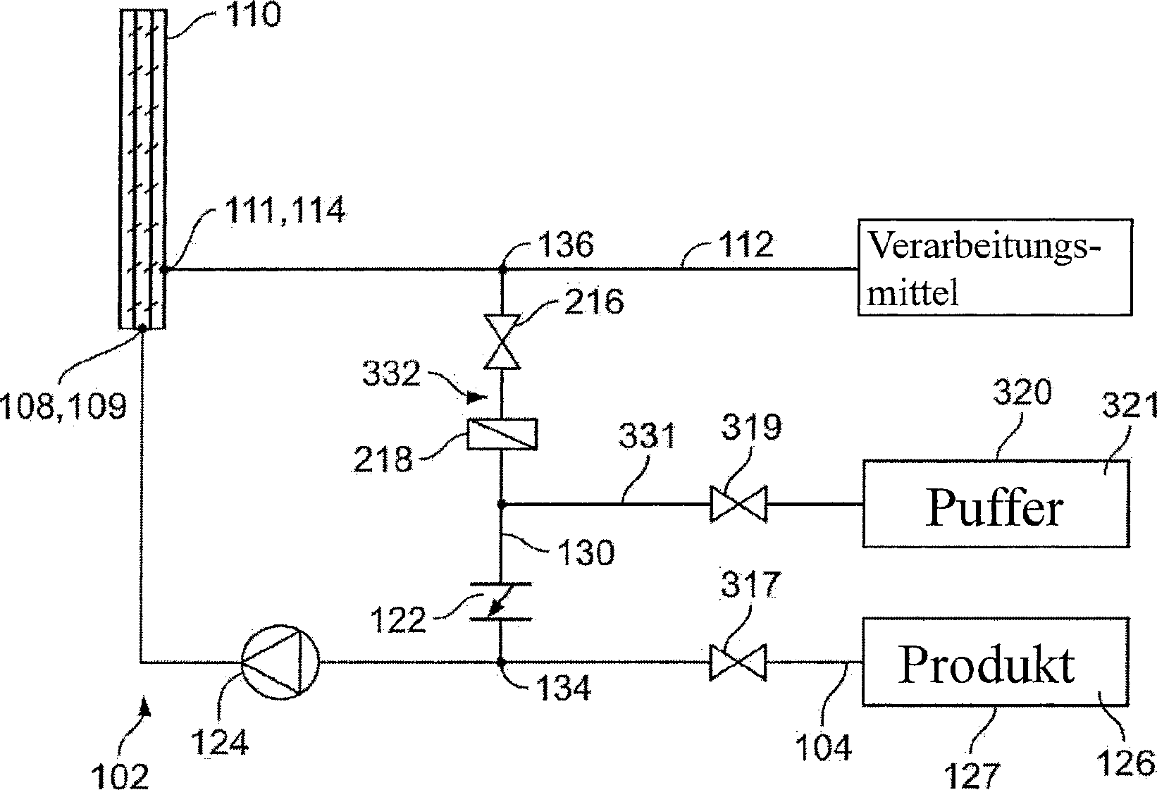
[0024] Fig. 3 zeigt ein Beispiel für ein System 300 zur Reduzierung der Migration eines oder mehrerer Viren über und durch den Virenentfernungsfilter 110, wenn der Zuflussstrom wieder aufgenommen wird, nachdem eine Reduzierung des Zuflussstroms durch den Virenentfernungsfilter 110 erfolgt ist. Das in Fig. 3 dargestellte System 300 ist ähnlich wie das in Fig. 2 dargestellte System 200 aufgebaut, mit gemeinsamen Komponenten, die mit gemeinsamen Bezugszeichen versehen sind, unterscheidet sich aber dadurch, dass das System 300 ein Rezirkulationssystem 332 beinhaltet, das sich vom Rezirkulationssystem 232 des Systems 200 unterscheidet. Insbesondere beinhaltet das Rezirkulationssystem 332 in diesem Beispiel das Rückschlagventil 122, das Absperrventil 216 und die Berstscheibe 218, aber auch ein zweites Absperrventil 317, ein drittes Absperrventil 319 und eine Quelle 320 der Rezirkulationspufferlösung 321 (d.h. eine zweite Pufferlösung).FIG. 3 shows an example of a system 300 for reducing the migration of one or more viruses over and through the virus removal filter 110 when the inflow flow is resumed after the inflow flow has been reduced by the virus removal filter 110. System 300 shown in FIG. 3 is constructed similarly to system 200 shown in FIG. 2, with common components that are provided with common reference numerals, but differs in that system 300 includes a recirculation system 332 that is different from the recirculation system 232 of the system 200 differs. In particular, the recirculation system 332 in this example includes the check valve 122, the shut-off valve 216 and the rupture disk 218, but also a second shut-off valve 317, a third shut-off valve 319 and a source 320 of the recirculation buffer solution 321 (i.e. a second buffer solution).
[0025] Wie in Fig. 3 dargestellt, ist das zweite Absperrventil 317 entlang der Einlassleitung 102 an einer Stelle zwischen der Pumpe 124 und der Einlassöffnung 104 angeordnet. Insbesondere ist das zweite Absperrventil 317 entlang der Eingangsleitung 102 zwischen der Eingangsöffnung 134 der Rezirkulationsleitung 130 und der Eingangsöffnung angeordnet. Wie das Absperrventil 216 hat auch das zweite Absperrventil 317 eine offene und eine geschlossene Position. Wenn sich das Absperrventil 317 jedoch in seiner geöffneten Position befindet, lässt das Ventil 317 einen Fluidstrom zwischen der Eingangsöffnung 104 und der Eingangsöffnung 134 zu. Wenn sich das Absperrventil 317 in seiner geöffneten Position befindet, lässt das Ventil 317 somit das Produkt 126 von der Quelle 127 zur Pumpe 124 fliessen. Umgekehrt verhindert das Ventil 317, wenn sich das Absperrventil 317 in seiner geschlossenen Position befindet, den Fluidstrom zwischen der Einlassöffnung 104 und der Einlassöffnung 134, so dass kein Produkt 126 zur Pumpe 124 fliessen kann (d.h. der Zuflussstrom ist Null).As shown in FIG. 3, the second shut-off valve 317 is arranged along the inlet line 102 at a location between the pump 124 and the inlet opening 104. In particular, the second shut-off valve 317 is arranged along the inlet line 102 between the inlet opening 134 of the recirculation line 130 and the inlet opening. Like the shutoff valve 216, the second shutoff valve 317 has an open and a closed position. However, when the shutoff valve 317 is in its open position, the valve 317 allows fluid flow between the inlet port 104 and the inlet port 134. Thus, when the shutoff valve 317 is in its open position, the valve 317 allows the product 126 to flow from the source 127 to the pump 124. Conversely, when the shut-off valve 317 is in its closed position, the valve 317 prevents fluid flow between the inlet port 104 and the inlet port 134 so that no product 126 can flow to the pump 124 (i.e. the inflow flow is zero).
[0026] Das dritte Absperrventil 319 und die Quelle 320 der Rezirkulationspufferlösung 321 sind fluidisch mit der Rezirkulationsleitung 130 verbunden. Im dargestellten Beispiel sind das dritte Absperrventil 319 und die Quelle 320 jeweils entlang einer Rezirkulationsleitung 331 angeordnet, die mit der Rezirkulationsleitung 130 zwischen dem Rückschlagventil 122 und der Berstscheibe 218 verbunden ist. Wenn die Rezirkulationsleitung 331 so mit der Rezirkulationsleitung 130 verbunden ist, ist das dritte Absperrventil 319 zwischen der Rezirkulationsleitung 130 und der Quelle 320 der Rezirkulationspufferlösung 321 angeordnet. Wie das Absperrventil 317 hat auch das dritte Absperrventil 319 eine offene und eine geschlossene Position. Wenn sich das Absperrventil 319 jedoch in seiner geöffneten Position befindet, ermöglicht das Ventil 319 den Fluidstrom zwischen der Quelle 320 und der Rezirkulationsleitung 130. Wenn sich das Absperrventil 319 in seiner geöffneten Position befindet, lässt das Ventil 319 somit die Rezirkulationspufferlösung 321 von der Quelle 320 zur Rezirkulationsleitung 130 fliessen. Umgekehrt verhindert das Ventil 319, wenn sich das Absperrventil 319 in seiner geschlossenen Position befindet, den Fluidstrom zwischen der Quelle 320 und der Rezirkulationsleitung 130.The third shut-off valve 319 and the source 320 of the recirculation buffer solution 321 are fluidly connected to the recirculation line 130. In the example shown, the third shut-off valve 319 and the source 320 are each arranged along a recirculation line 331 which is connected to the recirculation line 130 between the check valve 122 and the rupture disk 218. When the recirculation line 331 is thus connected to the recirculation line 130, the third shut-off valve 319 is arranged between the recirculation line 130 and the source 320 of the recirculation buffer solution 321. Like the shutoff valve 317, the third shutoff valve 319 has an open and a closed position. However, when the shutoff valve 319 is in its open position, the valve 319 allows fluid flow between the source 320 and the recirculation line 130. When the shutoff valve 319 is in its open position, the valve 319 thus releases the recirculation buffer solution 321 from the source 320 flow to recirculation line 130. Conversely, when the shutoff valve 319 is in its closed position, the valve 319 prevents fluid flow between the source 320 and the recirculation line 130.
[0027] Das System 300 arbeitet ähnlich wie das System 200 im Normalbetrieb und reagiert auf eine Reduzierung des Förderstroms in der Einlassleitung 102 (und damit des Filters 110). Insbesondere ist während des normalen Betriebs des Systems 300 das Rückschlagventil 122 geschlossen, das erste Absperrventil 216 geöffnet (obwohl es alternativ geschlossen sein kann), das zweite Absperrventil 317 geöffnet und das dritte Absperrventil 319 geschlossen, so dass das Produkt 126 durch die Eingangsleitung 102, durch den Filter 110 und aus dem System 200 über die Ausgangsleitung 112 strömt. Und wenn das Rückschlagventil 122 eine Zulassstromreduzierung in der Einlassleitung 102 erkennt, bewegt sich das Rückschlagventil 122 aus seiner geschlossenen Position in seine geöffnete Position und das erste Absperrventil 216 wird aus seiner geschlossenen Position in seine geöffnete Position bewegt (falls es geschlossen war), wodurch ein Rezirkulationskreislauf im System 300 entsteht, wie vorstehend in Verbindung mit dem System 200 beschrieben.The system 300 works similarly to the system 200 in normal operation and reacts to a reduction in the flow rate in the inlet line 102 (and thus the filter 110). In particular, during normal operation of system 300, check valve 122 is closed, first shutoff valve 216 is open (although it may alternatively be closed), second shutoff valve 317 is open, and third shutoff valve 319 is closed, so that product 126 through input line 102, flows through the filter 110 and out of the system 200 via the output line 112. And when the check valve 122 detects an admission flow reduction in the inlet line 102, the check valve 122 moves from its closed position to its open position and the first shut-off valve 216 is moved from its closed position to its open position (if it was closed), thereby causing a Recirculation cycle in system 300 is established as described above in connection with system 200.
[0028] Sobald jedoch die Reduzierung des Zuflussstroms beendet ist und der volle Zuflussstrom wieder aufgenommen wird, ist das System 300 so konfiguriert, dass es automatisch (d.h. ohne menschliches Zutun) alle in der Rückführungsleitung oder Rezirkulationsleitung 130 eingeschlossenen Flüssigkeiten aus der Rezirkulationsleitung 130 und aus dem System 300 herausströmen lässt. Insbesondere, sobald das Rückschlagventil 122 erkennt, dass der volle Zufluss wieder aufgenommen wurde, bewegt sich das Rückschlagventil 122 aus seiner geöffneten Position in seine geschlossene Position, und das System 200 bewirkt, dass das erste Absperrventil 216 aus seiner geöffneten Position in seine geschlossene Position übergeht, das zweite Absperrventil 317 aus seiner geöffneten Position in seine geschlossene Position übergeht und das dritte Absperrventil 319 aus seiner geschlossenen Position in seine offene Position übergeht. Während die Einlassleitung 102 von der Auslassleitung 112 fluidisch isoliert ist, strömt die Rezirkulationspufferlösung 321 von der Quelle 320 zum und durch das dritte Absperrventil 319, über die Rezirkulationsastleitung 331 und zum und durch das Rückschlagventil 122 über die Rezirkulationsleitung 130, Dabei prüft die Rezirkulationspufferlösung 321 alle Flüssigkeiten, die ansonsten in der Rezirkulationsleitung 130 eingeschlossen wären, wenn das Rückschlagventil 122 erkennt, dass der volle Zufluss wieder aufgenommen wurde. Diese eingeschlossene Flüssigkeit strömt anschliessend durch die Einlassleitung 102 zum und durch den Virusentfernungsfilter 110 und wird über die Auslassleitung 112 aus dem System 300 herausgeführt.However, as soon as the reduction of the inflow flow has ended and the full inflow flow is resumed, the system 300 is configured so that it automatically (ie without human intervention) all liquids enclosed in the return line or recirculation line 130 from the recirculation line 130 and out can flow out of the system 300. In particular, once check valve 122 detects that full flow has resumed, check valve 122 moves from its open position to its closed position, and system 200 causes first shutoff valve 216 to transition from its open position to its closed position , the second shut-off valve 317 changes from its open position to its closed position and the third shut-off valve 319 changes from its closed position to its open position. While the inlet line 102 is fluidly isolated from the outlet line 112, the recirculation buffer solution 321 flows from the source 320 to and through the third shut-off valve 319, via the recirculation branch line 331 and to and through the check valve 122 via the recirculation line 130. The recirculation buffer solution 321 checks everyone Liquids that would otherwise be trapped in recirculation line 130 when check valve 122 detects that full flow has resumed. This enclosed liquid then flows through the inlet line 102 to and through the virus removal filter 110 and is led out of the system 300 via the outlet line 112.
CH 714 987 A2 [0029] Es ist zu beachten, dass die Komponenten des Systems 100, des Systems 200 und des Systems 300 aus einem oder mehreren verschiedenen Materialien bestehen können. Vorzugsweise haben die Komponenten des Systems 100, des Systems 200 und des Systems 300, z.B. die Einlassleitung 102, die Auslassleitung 112 und die Rezirkulationsleitung 130, jeweils die Form einer Leitung aus einem Einwegmaterial, wie beispielsweise einem Kunststoffmaterial wie gammastabilem Kunststoff (das Gammastrahlung widerstehen kann). In einigen Beispielen können jedoch die Einlassleitung 102, die Auslassleitung 112, die Rezirkulationsleitung 130 und/oder andere Komponenten stattdessen aus einem metallischen Werkstoff (z.B. Edelstahl) bestehen.CH 714 987 A2 It should be noted that the components of system 100, system 200 and system 300 may be made from one or more different materials. Preferably, the components of system 100, system 200 and system 300, e.g. the inlet line 102, the outlet line 112 and the recirculation line 130, each in the form of a line made of a single-use material such as a plastic material such as gamma-stable plastic (which can withstand gamma radiation). However, in some examples, inlet line 102, outlet line 112, recirculation line 130, and / or other components may instead be made of a metallic material (e.g., stainless steel).
[0030] Der Fachmann erkennt dabei, dass in Bezug auf die oben beschriebenen Ausführungsformen eine Vielzahl von Modifikationen, Änderungen und Kombinationen vorgenommen werden können, ohne vom Umfang der Offenbarung abzuweichen, und dass solche Modifikationen, Änderungen und Kombinationen als im Bereich des erfinderischen Konzepts liegend anzusehen sind.Those skilled in the art will recognize that a variety of modifications, changes, and combinations can be made with respect to the above-described embodiments without departing from the scope of the disclosure, and that such modifications, changes, and combinations are considered to be within the scope of the inventive concept are to be seen.
Claims (23)

Applications Claiming Priority (1)
| Application Number | Priority Date | Filing Date | Title |
|---|---|---|---|
| US15/968,445 US10618007B2 (en) | 2018-05-01 | 2018-05-01 | Systems and methods of reducing virus migration through a virus removal filter after feed flow reduction |
Publications (1)
| Publication Number | Publication Date |
|---|---|
| CH714987A2 true CH714987A2 (en) | 2019-11-15 |
Family
ID=66334264
Family Applications (1)
| Application Number | Title | Priority Date | Filing Date |
|---|---|---|---|
| CH5632019A CH714987A2 (en) | 2018-05-01 | 2019-04-29 | Valve arrangement and method for reducing virus migration through a virus removal filter after reducing the inflow. |
Country Status (8)
| Country | Link |
|---|---|
| US (1) | US10618007B2 (en) |
| EP (1) | EP3563876A1 (en) |
| CN (1) | CN110420562B (en) |
| AR (1) | AR114849A1 (en) |
| BR (1) | BR102019008780A2 (en) |
| CA (1) | CA3041321A1 (en) |
| CH (1) | CH714987A2 (en) |
| RU (1) | RU2019113116A (en) |
Families Citing this family (1)
| Publication number | Priority date | Publication date | Assignee | Title |
|---|---|---|---|---|
| CN113289411B (en) * | 2021-05-26 | 2023-02-03 | 云南云天化红磷化工有限公司 | Automatic sequence control method for pressure filter |
Family Cites Families (8)
| Publication number | Priority date | Publication date | Assignee | Title |
|---|---|---|---|---|
| DE2837115A1 (en) | 1978-08-25 | 1980-03-06 | Bayer Ag | NEW METHOD FOR THE PRODUCTION OF STERILE SOLIDS |
| US5017292A (en) | 1990-05-10 | 1991-05-21 | Millipore Corporation | Membrane, process and system for isolating virus from solution |
| US8546127B2 (en) | 2008-06-30 | 2013-10-01 | General Electric Company | Bacteria/RNA extraction device |
| US8956532B1 (en) | 2011-02-17 | 2015-02-17 | Jerry M. James, Jr. | Well water recirculating system |
| ES2536239T3 (en) * | 2012-07-26 | 2015-05-21 | Manfred Völker | RO installation and procedure for the disinfection of RO system ducts |
| US9616388B2 (en) | 2013-03-15 | 2017-04-11 | Culligan International Company | Reverse osmosis system with an automated modulated bypass |
| DE102013113641A1 (en) | 2013-12-06 | 2015-06-11 | Winterhalter Gastronom Gmbh | Apparatus and method for water treatment |
| WO2015175790A1 (en) | 2014-05-15 | 2015-11-19 | Tokyo Electron Limited | Method and apparatus for increased recirculation and filtration in a photoresist dispense system |
-
2018
- 2018-05-01 US US15/968,445 patent/US10618007B2/en not_active Expired - Fee Related
-
2019
- 2019-04-26 CA CA3041321A patent/CA3041321A1/en not_active Abandoned
- 2019-04-29 CN CN201910354614.2A patent/CN110420562B/en not_active Expired - Fee Related
- 2019-04-29 AR ARP190101128A patent/AR114849A1/en active IP Right Grant
- 2019-04-29 RU RU2019113116A patent/RU2019113116A/en unknown
- 2019-04-29 CH CH5632019A patent/CH714987A2/en not_active Application Discontinuation
- 2019-04-30 EP EP19171780.0A patent/EP3563876A1/en not_active Withdrawn
- 2019-04-30 BR BR102019008780A patent/BR102019008780A2/en not_active IP Right Cessation
Also Published As
| Publication number | Publication date |
|---|---|
| EP3563876A1 (en) | 2019-11-06 |
| AR114849A1 (en) | 2020-10-21 |
| CN110420562A (en) | 2019-11-08 |
| RU2019113116A (en) | 2020-11-02 |
| US10618007B2 (en) | 2020-04-14 |
| CN110420562B (en) | 2023-02-03 |
| BR102019008780A2 (en) | 2019-12-10 |
| US20190336915A1 (en) | 2019-11-07 |
| CA3041321A1 (en) | 2019-11-01 |
Similar Documents
| Publication | Publication Date | Title |
|---|---|---|
| DE69529278T2 (en) | FILTRATION DEVICE FOR REMOVING LEUKOCYTES | |
| DE69411568T2 (en) | SELF-BLEEDING FILTER DEVICE | |
| DE69405038T2 (en) | Device and method for injecting a liquid produced by filtration pyrogen-free and sterile | |
| DE69732249T2 (en) | CASSETTE FOR CONTROLLING AND PUMPING FLUIDS | |
| DE3688441T2 (en) | Separator for gas bubbles from liquids. | |
| DE3877852T2 (en) | SELF-WORKING FILTER. | |
| DE69530398T2 (en) | DRIP CHAMBER HEAD | |
| DE2458405A1 (en) | FILTER HOLDER | |
| EP3810747B1 (en) | Modular processing system and method for the modular construction of a processing system | |
| DE2611212A1 (en) | DEVICE FOR TREATMENT OF WATER ADDICTION (ASZITES) | |
| EP1469928B1 (en) | Sterile system and method for filtering biological or medical liquids, especially blood or blood constituents | |
| EP0790064B1 (en) | Procedure and infusion set for consecutively emptying a plurality,in particular two recipients containing liquid drugs | |
| WO2002020141A1 (en) | Device and method for separating undissolved constituents out of biological fluids | |
| EP3861096B1 (en) | Bioprocessing installation | |
| DE3020449A1 (en) | FILTER DEVICE FOR AN INTRAVENOES INFUSION SYSTEM | |
| WO2006094752A1 (en) | Venous bubble trap | |
| DE102009012347A1 (en) | Filter assembly and a method for producing a filter assembly | |
| CH714987A2 (en) | Valve arrangement and method for reducing virus migration through a virus removal filter after reducing the inflow. | |
| DE69604345T2 (en) | Device for sorting materials by sedimentation | |
| DE2925143A1 (en) | DEVICE FOR CONTINUOUS PLASMAPHERESIS | |
| DE212016000294U1 (en) | Y connector and set for continuous ambulatory peritoneal dialysis | |
| DE69620706T2 (en) | Fluid filter assembly | |
| EP4019935B1 (en) | Integrity test for a double filter capsule | |
| DE1159394B (en) | Ultrafilter with a semipermeable filter membrane made of cellulose derivative | |
| DE19820158A1 (en) | Blood oxygenation method and apparatus |
Legal Events
| Date | Code | Title | Description |
|---|---|---|---|
| AZW | Rejection (application) |