CN100458917C - Method and mechanism for optimizing suspension resonance of hard disk drive - Google Patents
Method and mechanism for optimizing suspension resonance of hard disk drive Download PDFInfo
- Publication number
- CN100458917C CN100458917C CNB2003801105250A CN200380110525A CN100458917C CN 100458917 C CN100458917 C CN 100458917C CN B2003801105250 A CNB2003801105250 A CN B2003801105250A CN 200380110525 A CN200380110525 A CN 200380110525A CN 100458917 C CN100458917 C CN 100458917C
- Authority
- CN
- China
- Prior art keywords
- slider
- test
- suspension
- slide
- air bearing
- Prior art date
- Legal status (The legal status is an assumption and is not a legal conclusion. Google has not performed a legal analysis and makes no representation as to the accuracy of the status listed.)
- Expired - Fee Related
Links
Images


Classifications
-
- G—PHYSICS
- G11—INFORMATION STORAGE
- G11B—INFORMATION STORAGE BASED ON RELATIVE MOVEMENT BETWEEN RECORD CARRIER AND TRANSDUCER
- G11B5/00—Recording by magnetisation or demagnetisation of a record carrier; Reproducing by magnetic means; Record carriers therefor
- G11B5/48—Disposition or mounting of heads or head supports relative to record carriers ; arrangements of heads, e.g. for scanning the record carrier to increase the relative speed
- G11B5/58—Disposition or mounting of heads or head supports relative to record carriers ; arrangements of heads, e.g. for scanning the record carrier to increase the relative speed with provision for moving the head for the purpose of maintaining alignment of the head relative to the record carrier during transducing operation, e.g. to compensate for surface irregularities of the latter or for track following
- G11B5/60—Fluid-dynamic spacing of heads from record-carriers
- G11B5/6005—Specially adapted for spacing from a rotating disc using a fluid cushion
-
- G—PHYSICS
- G11—INFORMATION STORAGE
- G11B—INFORMATION STORAGE BASED ON RELATIVE MOVEMENT BETWEEN RECORD CARRIER AND TRANSDUCER
- G11B5/00—Recording by magnetisation or demagnetisation of a record carrier; Reproducing by magnetic means; Record carriers therefor
- G11B5/455—Arrangements for functional testing of heads; Measuring arrangements for heads
- G11B5/4555—Arrangements for functional testing of heads; Measuring arrangements for heads by using a spin-stand, i.e. a spinning disc or simulator
-
- G—PHYSICS
- G11—INFORMATION STORAGE
- G11B—INFORMATION STORAGE BASED ON RELATIVE MOVEMENT BETWEEN RECORD CARRIER AND TRANSDUCER
- G11B5/00—Recording by magnetisation or demagnetisation of a record carrier; Reproducing by magnetic means; Record carriers therefor
- G11B5/48—Disposition or mounting of heads or head supports relative to record carriers ; arrangements of heads, e.g. for scanning the record carrier to increase the relative speed
- G11B5/58—Disposition or mounting of heads or head supports relative to record carriers ; arrangements of heads, e.g. for scanning the record carrier to increase the relative speed with provision for moving the head for the purpose of maintaining alignment of the head relative to the record carrier during transducing operation, e.g. to compensate for surface irregularities of the latter or for track following
- G11B5/60—Fluid-dynamic spacing of heads from record-carriers
- G11B5/6005—Specially adapted for spacing from a rotating disc using a fluid cushion
- G11B5/6082—Design of the air bearing surface
-
- G—PHYSICS
- G11—INFORMATION STORAGE
- G11B—INFORMATION STORAGE BASED ON RELATIVE MOVEMENT BETWEEN RECORD CARRIER AND TRANSDUCER
- G11B5/00—Recording by magnetisation or demagnetisation of a record carrier; Reproducing by magnetic means; Record carriers therefor
- G11B5/127—Structure or manufacture of heads, e.g. inductive
- G11B5/31—Structure or manufacture of heads, e.g. inductive using thin films
- G11B5/3163—Fabrication methods or processes specially adapted for a particular head structure, e.g. using base layers for electroplating, using functional layers for masking, using energy or particle beams for shaping the structure or modifying the properties of the basic layers
- G11B5/3173—Batch fabrication, i.e. producing a plurality of head structures in one batch
-
- G—PHYSICS
- G11—INFORMATION STORAGE
- G11B—INFORMATION STORAGE BASED ON RELATIVE MOVEMENT BETWEEN RECORD CARRIER AND TRANSDUCER
- G11B5/00—Recording by magnetisation or demagnetisation of a record carrier; Reproducing by magnetic means; Record carriers therefor
- G11B5/48—Disposition or mounting of heads or head supports relative to record carriers ; arrangements of heads, e.g. for scanning the record carrier to increase the relative speed
- G11B5/4806—Disposition or mounting of heads or head supports relative to record carriers ; arrangements of heads, e.g. for scanning the record carrier to increase the relative speed specially adapted for disk drive assemblies, e.g. assembly prior to operation, hard or flexible disk drives
- G11B5/4826—Mounting, aligning or attachment of the transducer head relative to the arm assembly, e.g. slider holding members, gimbals, adhesive
-
- Y—GENERAL TAGGING OF NEW TECHNOLOGICAL DEVELOPMENTS; GENERAL TAGGING OF CROSS-SECTIONAL TECHNOLOGIES SPANNING OVER SEVERAL SECTIONS OF THE IPC; TECHNICAL SUBJECTS COVERED BY FORMER USPC CROSS-REFERENCE ART COLLECTIONS [XRACs] AND DIGESTS
- Y10—TECHNICAL SUBJECTS COVERED BY FORMER USPC
- Y10T—TECHNICAL SUBJECTS COVERED BY FORMER US CLASSIFICATION
- Y10T29/00—Metal working
- Y10T29/49—Method of mechanical manufacture
- Y10T29/49002—Electrical device making
- Y10T29/4902—Electromagnet, transformer or inductor
- Y10T29/49021—Magnetic recording reproducing transducer [e.g., tape head, core, etc.]
- Y10T29/49032—Fabricating head structure or component thereof
- Y10T29/49036—Fabricating head structure or component thereof including measuring or testing
Landscapes
- Adjustment Of The Magnetic Head Position Track Following On Tapes (AREA)
- Supporting Of Heads In Record-Carrier Devices (AREA)
Abstract
本发明公开了一种使用测试滑块来测试磁头万向悬挂支架组件的共振性能的系统和方法。该测试滑块有两条带的空气轴承表面以允许测试滑块在表面上方滑行,且具有质量等于电滑块和微致动器的组合质量的块。滑块的前缘被逐渐减少且有主空气凹槽以便于滑行。在与空气轴承表面相对的测试滑块的一侧上的背面台阶在滑块和磁头万向悬挂支架组件凸出部之间保持平行的间隙。
The present invention discloses a system and method for testing the resonant performance of a head gimbal suspension assembly using a test slider. The test slider has a two-strip air bearing surface to allow the test slider to glide over the surface and has a mass equal to the combined mass of the electric slider and the microactuator. The leading edge of the slider is tapered and has a main air groove to facilitate gliding. A back step on the side of the test slider opposite the air bearing surface maintains a parallel gap between the slider and the head gimbal suspension assembly protrusion.
Description
技术领域 technical field
本发明的目的在于将滑块连接至磁头悬架。更具体地,本发明与减少将滑块耦合至磁头悬架所需要的粘合剂的量有关。The object of the present invention is to connect the slider to the head suspension. More specifically, the invention relates to reducing the amount of adhesive required to couple a slider to a head suspension.
背景技术 Background technique
图1说明了本领域典型的硬盘驱动器设计。硬盘驱动器100是通用的信息存储装置,基本上由一系列利用磁性的读写元件存取的可旋转盘104组成。一般被称为转换器的这些数据传递元件,通常被滑块主体110所承载并被嵌入滑块主体110中。在形成于盘上的离散数据磁道上方,滑块主体110由包括与致动器臂106相连的悬架102的磁头万向悬挂支架组件(HGA)保持在很近的位置上,以此允许读/写操作可被实施。利用音圈电动机112HGA围绕枢轴108旋转。为了相对于盘表面适当地放置转换器,在滑块主体110上形成的空气轴承表面(ABS)经受着流态的气流,该流态的气流提供了足够的升力以使滑块110(和转换器)“飘浮”在盘数据磁道之上。磁盘104的高速旋转产生了沿其表面以基本上平行于该盘切向速度方向的气流或者风的流。气流与滑块主体110的ABS的结合,使得滑块在自旋的盘上漂浮。实际上,悬置的滑块110通过这个自激的空气轴承与盘表面104物理分离。滑块110的ABS通常被配置在面对旋转盘104(参见下文)的滑块表面上,并且极大地影响了滑块在各种状态下于盘上浮动的能力。Figure 1 illustrates a typical hard drive design in the art. A
图2a-d说明了现有技术的、用于将滑块110和微致动器202耦合至致动器臂104的悬架102的方法。如图2a所示,滑块110被耦合至微致动器202。该微致动器202提供了比致动器臂104更精细的滑块移动控制的度。微致动器202具有基底204,该基底204带有从基底204突出的两个臂206。压电(PZT)材料条带208被耦合至每个致动器臂206的一侧。施加到PZT条带208的电荷使其能够扩张或者收缩,移动致动器臂206。滑块110在接合点210处接合到致动器臂206上。2a-d illustrate a prior art method for
如图2b所示,微致动器202经由悬架凸出部(tongue)212耦合至悬架102。悬架102耦合至基板214。基板具有允许基板214围绕枢轴旋转的孔216。一系列迹线(trace)218沿着悬架102和悬架凸出部212的长度伸展以电耦合至滑块110和微致动器202。迹线218经由安装在基板214上的一系列结合片220电耦合至控制电路。如图2c所示,微致动器202被定位以使在该微致动器202和悬架凸出部212之间保持一个间隙222,且在滑块110和悬架凸出部212之间延伸。As shown in FIG. 2 b ,
悬架的共振性能是HGA共振控制的主要因素。共振性能在制造过程中被优化以改进共振控制。用于测试悬架共振性能的传统方法是使用机械的HGA。如图2d所示,实际的滑块110被完全罐封到悬架凸出部212以产生机械的HGA。该机械的HGA被加载到共振测试器。共振测试器能够使用激光多普勒效应来监测HGA基板的机械振动过程中的频率响应或对其采样。基于测试的结果可以对制造过程或设计进行校正。本实施例中的滑块在测试完成之后易于被循环利用。本测试方法对于包括微致动器的HGA变得更难。安装除了滑块以外的微致动器需要更高精度的安装设备或夹具,该安装设备或夹具主要用于在微致动器和悬架凸出部之间保持一个平行间隙。另外,微致动器并不易于使用和被循环利用,因为微致动器是易碎的且它的制造难度大、价格昂贵。The resonance performance of the suspension is the main factor for HGA resonance control. Resonance performance is optimized during manufacturing to improve resonance control. The traditional method used to test suspension resonance performance is to use a mechanical HGA. As shown in Figure 2d, the
发明内容 Contents of the invention
按照本发明的第一方面,提供一种方法,包括以下步骤:将测试滑块耦合至悬架而代替具有微致动器的滑块;以及测量悬架的共振和W-曲线;其中所述测试滑块在与空气轴承表面相对的块的一侧上具有台阶以在所述测试滑块和悬架之间保持间隙;以及沿着所述空气轴承表面设置主空气凹槽。According to a first aspect of the present invention there is provided a method comprising the steps of: coupling a test slider to a suspension instead of a slider with a microactuator; and measuring the resonance and W-curve of the suspension; wherein the a test slide having a step on the side of the block opposite the air bearing surface to maintain clearance between the test slide and the suspension; and a primary air groove along the air bearing surface.
其中所述测试滑块具有基本等于所述具有微致动器的滑块的质量,所述测试滑块具有基本等于所述具有微致动器的滑块的外形。所述测试滑块具有基本等于所述具有微致动器的滑块的重量平衡。所述测试滑块具有基本等于所述具有微致动器的滑块的空气轴承特性。所述测试滑块具有空气轴承表面以允许所述测试滑块在盘介质表面上方滑行。所述测试滑块在所述台阶的表面上通过局部罐封粘合而耦合至所述悬架,或者所述测试滑块通过局部罐封而耦合至所述悬架。Wherein the test slider has a mass substantially equal to that of the slider with microactuators, and the test slider has a profile substantially equal to that of the slider with microactuators. The test slider had a weight balance substantially equal to that of the slider with microactuators. The test slider had air bearing characteristics substantially equal to the slider with microactuators. The test slider has an air bearing surface to allow the test slider to slide over the disk media surface. The test slide is coupled to the suspension by partial potting adhesive on the surface of the step, or the test slide is coupled to the suspension by partial potting.
按照本发明的第一方面的方法,还包括当测量的共振超出预定范围时对所述悬架进行机械性修改。The method according to the first aspect of the present invention further comprises mechanically modifying said suspension when the measured resonance is outside a predetermined range.
按照本发明的第二方面,提供一种测试滑块,包含:质量基本等于具有微致动器的滑块的质量的块,以在悬架共振测试期间代表微致动器和滑块;空气轴承表面,以允许所述块在盘介质上方滑行;台阶,所述台阶位于与所述空气轴承表面相对的所述块的一侧上,以在所述块和悬架之间保持间隙;以及沿着所述空气轴承表面设置有主空气凹槽。According to a second aspect of the present invention there is provided a test slider comprising: a mass substantially equal to the mass of the slider with the microactuator to represent the microactuator and slider during suspension resonance testing; air a bearing surface to allow the block to slide over the disk media; a step on the side of the block opposite the air bearing surface to maintain clearance between the block and the suspension; and A main air groove is provided along the air bearing surface.
其中所述块具有基本等于具有微致动器的滑块的外形,所述块具有基本等于具有微致动器的滑块的重量平衡。Wherein said block has a profile substantially equal to that of a slider with microactuators, said block having a weight balance substantially equal to that of a slider with microactuators.
按照本发明第二方面的测试滑块,其中所述空气轴承表面的前缘被逐渐减少。A test slider according to a second aspect of the present invention, wherein the leading edge of said air bearing surface is tapered.
按照本发明的第三方面,还是提供一种方法,包括:研磨陶瓷直列条以产生光滑的空气轴承表面;把所述陶瓷直列条切成将被耦合至悬架的测试滑块;在与所述空气轴承表面相对的所述陶瓷直列条的一侧上磨削台阶以在所述测试滑块和所述悬架之间保持间隙;以及在所述空气轴承表面上磨削主空气凹槽。According to a third aspect of the present invention, there is also provided a method comprising: grinding a ceramic inline bar to produce a smooth air bearing surface; cutting said ceramic inline bar into a test slider to be coupled to a suspension; grinding a step on the side of the ceramic in-line bar opposite the air bearing surface to maintain clearance between the test slider and the suspension; and grinding a main air groove on the air bearing surface.
附图说明 Description of drawings
图1说明了本领域典型的硬盘驱动设计。Figure 1 illustrates a typical hard drive design in the art.
图2a-d说明了现有技术的、用于将滑块和微致动器耦合至致动器臂的悬架的方法。Figures 2a-d illustrate a prior art method for coupling a slider and a microactuator to a suspension of an actuator arm.
图3a-d说明了根据本发明实施例的测试滑块302。3a-d illustrate a
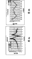
图4a-b以曲线图的形式说明了滑块和微致动器以及测试滑块的性能比较。Figure 4a–b illustrates the performance comparison of sliders and microactuators and test sliders in the form of graphs.
图5a-p说明了根据本发明实施例的用于制作测试滑块的过程。Figures 5a-p illustrate a process for fabricating a test slider according to an embodiment of the present invention.
图6以流程图形式说明了根据本发明实施例的用于制作测试滑块的过程。FIG. 6 illustrates in flowchart form a process for making a test slider according to an embodiment of the present invention.
具体实施方式 Detailed ways
本发明公开了一种使用测试滑块来测试磁头万向悬挂支架组件的共振性能的系统和方法。在一个实施例中,测试滑块具有一个两条带的空气轴承表面以允许测试滑块在表面上方滑动,且具有一个质量(mass)等于电滑块和微致动器的组合质量的块。滑块的前缘是锥形且具有主空气凹槽以便于滑动。与空气轴承面相对的测试滑块的一侧上的背面台阶在滑块和磁头万向悬挂支架组件的悬架凸出部之间保持一个平行间隙。The invention discloses a system and a method for testing the resonance performance of a gimbal suspension bracket assembly of a magnetic head by using a test slider. In one embodiment, the test slider has a two-band air bearing surface to allow the test slider to slide over the surface, and has a mass equal to the combined mass of the electric slider and microactuator. The leading edge of the slider is tapered and has main air grooves for easy sliding. The backside step on the side of the test slider opposite the air bearing surface maintains a parallel gap between the slider and the suspension bosses of the head gimbal assembly.
在一个实施例中,机械的磁头万向悬挂支架组件(HGA)被加载到可移动的HGA安装块上。该块被加载到共振测试器的共振震动器上。该共振测试器能够精确地测量HGA的机械共振。该共振测试器能使用激光多普勒振动计来监测HGA基板的机械震动过程中的频率响应或对其采样。共振测试器提供量级和相位对频率的输出图表。另外,共振测试器提供由傅立叶分析器处理的共振峰值的幅度和频率的列表。这允许悬架共振在设计和制造过程中被控制。如果共振频移或者增益比期望的值高,则能够基于测试结果对制造过程或设计进行校正。校正包括,例如修改悬架结构的几何结构或者对制造过程进行优化。该测试滑块在完成测试后易于被循环利用。In one embodiment, a mechanical head gimbal assembly (HGA) is loaded onto a movable HGA mounting block. The block is loaded onto the resonance vibrator of the resonance tester. This resonance tester can accurately measure the mechanical resonance of HGA. The resonance tester can use a laser Doppler vibrometer to monitor or sample the frequency response during mechanical vibration of the HGA substrate. The Resonance Tester provides output plots of magnitude and phase versus frequency. Additionally, the Resonance Tester provides a listing of the magnitude and frequency of the resonance peaks processed by the Fourier Analyzer. This allows suspension resonance to be controlled during design and manufacturing. If the resonant frequency shifts or the gain is higher than expected, corrections to the manufacturing process or design can be made based on the test results. Correction includes, for example, modifying the geometry of the suspension structure or optimizing the manufacturing process. The test slider is easily recycled after the test is completed.
图3a-d说明了测试滑块302的一个实施例。测试滑块302的机械块的质量和外形等于滑块110和微致动器202组合的质量和外形。测试滑块的空气轴承特性基本等价于滑块和微致动器。如图3a所示,测试滑块302具有空气轴承表面(ABS)304,其允许滑块位于例如盘驱动的硬盘的表面上方的气流上。在所示的实施例中,ABS304具有两个条带。每个条带304的边缘306在测试滑块302的前缘处逐渐减少,以引导滑块ABS上的空气以及便于取下滑块,同时通过连贯的力保持磁头在盘上飘浮。主空气凹槽308位于两个ABS条带304之间。侧轨(side rail)表面凹部310位于每个ABS条带304的外侧上。侧轨表面凹部310减少了当磁头加载到盘上或从盘卸载时,由于尖角磁头对盘的碰撞或者冲击的危险。如图3b的实施例中所示,与ABS条带304相对的测试滑块的一侧可具有台阶312。该台阶312可位于滑块302的前缘上。如图3c所示,该台阶312在测试滑块302与悬架凸出部212之间保持一个间隙222。如图3d所示,测试滑块302耦合至悬架102以测试悬架102的共振控制。在一个实施例中,在将测试滑块302安装到悬架凸出部212之前,该测试滑块302通过局部罐封台阶312的表面而耦合至悬架102。环氧树脂或树脂可以用于进行耦合。环氧树脂可以局部地添加到悬架凸出部212的前缘或者添加到测试滑块的台阶表面312上以用于更为可靠的安装。One embodiment of a
图4a-b以曲线图的形式说明了滑块和微致动器以及测试滑块的性能比较。如图4a所示,滑块与微致动器402及测试滑块404的增益(以dB计)对频率(以kHz计)的共振比较产生几乎相同的结果。如图4b所示,滑块与微致动器406及测试滑块404的增益(以dB计)对顶点高度(以百万分之一英寸计)的w曲线比较产生几乎相同的结果。Figure 4a–b illustrates the performance comparison of sliders and microactuators and test sliders in the form of graphs. As shown in Figure 4a, comparison of gain (in dB) versus frequency (in kHz) resonance of the slider and microactuator 402 and test slider 404 yielded nearly identical results. As shown in FIG. 4b, a comparison of w curves of gain (in dB) versus apex height (in millionths of an inch) for the slider and
图5a-p说明了用于制作测试滑块的过程的一个实施例。如图5a所示,陶瓷直列条(row bar)502被施加到研磨轮504。该研磨轮504在直列条502上产生光滑的空气轴承表面304,如图5b所示。如图5c所示,直列条502的前缘被施加到研磨轮504。该研磨轮504在直列条502的空气轴承表面304上产生锥形边缘306,如图5d所示。如图5e所示,砂轮506被施加到直列条502。砂轮506生成侧轨表面凹部310,如图5f所示。如图5g所示,砂轮506再次被施加到直列条502。砂轮506横过直列条磨削出一个道,如图5h所示。该道担当主空气凹槽308,如图5i所示。如图5j所示,砂轮506被施加到直列条502。砂轮506产生道508。在一个实施例中,道508的宽度是侧轨表面凹部310宽度的两倍。切割轮510然后切断道508的中央,从而将道508分割成两个侧轨310,如图5k所示。另一方面,砂轮506用于在道508的中央磨削穿过直列条502,而道508被加宽以容纳更宽的轮506。直列条502的断片是测试滑块302,如图51所示。如图5m所示,砂轮512的边缘被施加到与空气轴承表面304相对的一侧,以产生一个台阶312。在如图5n所示的另一个实施例中,砂轮512的边缘被施加到与前缘相对的一侧以产生一个台阶312。产物被清理以产生如图5p所示的成品测试滑块302。Figures 5a-p illustrate one embodiment of a process for making a test slider. Ceramic row bars 502 are applied to a
图6以流程图方式说明了用于制作测试滑块302的过程的一个实施例。直列条502被研磨以产生光滑的空气轴承表面304(块610)。直列条502然后被研磨以在前缘处产生锥形表面306(块620)。侧轨表面凹部310在空气轴承表面304上从邻接于直列条502前缘的边缘被磨削出来(块630)。主空气凹槽308然后在空气轴承表面304上平行于侧轨表面凹部310从直列条502磨削出来(块640)。第二侧轨表面凹部508的尺寸是第一侧轨表面凹部的双倍,且在空气轴承表面304上从直列条502磨削出来(块650)。直列条502接着通过第二侧轨表面凹部508的中央被切开(块660)。台阶312从测试滑块302的背面被磨削出来(块670)。然后清理测试滑块302且备用(块680)。FIG. 6 illustrates one embodiment of a process for making a
Claims (14)
Applications Claiming Priority (1)
| Application Number | Priority Date | Filing Date | Title |
|---|---|---|---|
| PCT/CN2003/000868 WO2005038781A1 (en) | 2003-10-16 | 2003-10-16 | Method and mechanism of the suspension resonance optimization for the hard disk driver |
Publications (2)
| Publication Number | Publication Date |
|---|---|
| CN1860529A CN1860529A (en) | 2006-11-08 |
| CN100458917C true CN100458917C (en) | 2009-02-04 |
Family
ID=34438170
Family Applications (1)
| Application Number | Title | Priority Date | Filing Date |
|---|---|---|---|
| CNB2003801105250A Expired - Fee Related CN100458917C (en) | 2003-10-16 | 2003-10-16 | Method and mechanism for optimizing suspension resonance of hard disk drive |
Country Status (3)
| Country | Link |
|---|---|
| US (2) | US7377190B2 (en) |
| CN (1) | CN100458917C (en) |
| WO (1) | WO2005038781A1 (en) |
Families Citing this family (8)
| Publication number | Priority date | Publication date | Assignee | Title |
|---|---|---|---|---|
| CN100458917C (en) * | 2003-10-16 | 2009-02-04 | 新科实业有限公司 | Method and mechanism for optimizing suspension resonance of hard disk drive |
| US7701675B2 (en) | 2005-12-16 | 2010-04-20 | Sae Magnetics (H.K.) Ltd. | Micro-actuator mounting structure capable of maintaining a substantially constant gap between a top support of a micro-actuator and a suspension during use |
| JP4847140B2 (en) * | 2006-01-20 | 2011-12-28 | 日本発條株式会社 | Head, gimbal assembly vibration characteristics measuring device |
| US8169745B2 (en) * | 2007-07-25 | 2012-05-01 | Sae Magnetics (H.K.) Ltd. | Head gimbal assembly having balanced weight, and disk drive unit with the same |
| CN108520762B (en) * | 2018-03-21 | 2020-05-22 | 西安交通大学 | Method and device for accelerated degradation test of batch hard disks under vibration environment |
| US12555599B2 (en) | 2023-11-30 | 2026-02-17 | International Business Machines Corporation | Folded spring tape track following actuator |
| US12266387B1 (en) * | 2023-11-30 | 2025-04-01 | International Business Machines Corporation | Reworkable tape track following actuator |
| US12462836B1 (en) | 2024-12-12 | 2025-11-04 | International Business Machines Corporation | Spring suspension with independent reader and writer following actuator |
Citations (2)
| Publication number | Priority date | Publication date | Assignee | Title |
|---|---|---|---|---|
| JPH09147356A (en) * | 1995-11-22 | 1997-06-06 | Fujitsu Ltd | Floating assurance test method for magnetic disk and bump disk |
| CN1240528A (en) * | 1996-12-04 | 2000-01-05 | 西加特技术有限公司 | Leading edge slider microactuator |
Family Cites Families (35)
| Publication number | Priority date | Publication date | Assignee | Title |
|---|---|---|---|---|
| US4416144A (en) * | 1982-04-21 | 1983-11-22 | Sperry Corporation | Apparatus for evaluating slider flying dynamics |
| JPH05109058A (en) * | 1991-10-16 | 1993-04-30 | Nec Corp | Device and method for evaluation test of durability of magnetic disk |
| US5606359A (en) * | 1994-06-30 | 1997-02-25 | Hewlett-Packard Company | Video on demand system with multiple data sources configured to provide vcr-like services |
| WO1996031981A1 (en) * | 1995-04-07 | 1996-10-10 | Sony Corporation | Method and apparatus for editing compressed video signal, and decoder |
| US5828370A (en) * | 1996-07-01 | 1998-10-27 | Thompson Consumer Electronics Inc. | Video delivery system and method for displaying indexing slider bar on the subscriber video screen |
| DE69833848T2 (en) * | 1997-01-06 | 2006-11-23 | Philips Intellectual Property & Standards Gmbh | DEVICE FOR READING AN IMAGE SENSOR MATRIX |
| US6222979B1 (en) * | 1997-02-18 | 2001-04-24 | Thomson Consumer Electronics | Memory control in trick play mode |
| US6201927B1 (en) * | 1997-02-18 | 2001-03-13 | Mary Lafuze Comer | Trick play reproduction of MPEG encoded signals |
| US6201668B1 (en) * | 1997-07-03 | 2001-03-13 | Seagate Technology Llc | Gimbal-level piezoelectric microactuator |
| US5979249A (en) * | 1998-06-09 | 1999-11-09 | Samsung Electronics Co., Ltd. | Actuator resonance tester for a disk drive |
| FR2782437B1 (en) * | 1998-08-14 | 2000-10-13 | Thomson Multimedia Sa | MPEG STREAM SWITCHING METHOD |
| JP2000268517A (en) * | 1999-03-15 | 2000-09-29 | Nec Corp | Magnetic disk device and its slider mechanism |
| US20060093045A1 (en) * | 1999-06-29 | 2006-05-04 | Roger Anderson | Method and apparatus for splicing |
| US7027713B1 (en) * | 1999-11-30 | 2006-04-11 | Sharp Laboratories Of America, Inc. | Method for efficient MPEG-2 transport stream frame re-sequencing |
| US6658199B1 (en) * | 1999-12-16 | 2003-12-02 | Sharp Laboratories Of America, Inc. | Method for temporally smooth, minimal memory MPEG-2 trick play transport stream construction |
| US6549020B2 (en) * | 2000-02-24 | 2003-04-15 | Seagate Technology Llc | Cartridge screening technique by using the electrical dynamic bearing resistance |
| GB0007868D0 (en) * | 2000-03-31 | 2000-05-17 | Koninkl Philips Electronics Nv | Methods and apparatus for editing digital video recordings and recordings made by such methods |
| JP3675315B2 (en) | 2000-08-24 | 2005-07-27 | Tdk株式会社 | Head gimbal assembly having an actuator for minute positioning of a head element and disk apparatus having the head gimbal assembly |
| JP2002074871A (en) | 2000-08-31 | 2002-03-15 | Tdk Corp | Head gimbals assembly equipped with actuator for fine positioning, disk device equipped with head gimbals assembly, and manufacturing method for head gimbals assembly |
| JP4007767B2 (en) | 2001-01-18 | 2007-11-14 | 日本碍子株式会社 | Piezoelectric / electrostrictive device and manufacturing method thereof |
| JP2002298526A (en) * | 2001-04-02 | 2002-10-11 | Shinka Jitsugyo Kk | Actuator for finely positioning head element, head gimbal assembly provided with the actuator, and method for manufacturing the head gimbal assembly |
| JP3975688B2 (en) * | 2001-04-23 | 2007-09-12 | 新科實業有限公司 | Head element micropositioning actuator, head gimbal assembly provided with the actuator, and method of manufacturing the actuator |
| US20030093800A1 (en) * | 2001-09-12 | 2003-05-15 | Jason Demas | Command packets for personal video recorder |
| US7398005B2 (en) * | 2001-12-19 | 2008-07-08 | Thomson Licensing | Trick mode playback of recorded video |
| US7274857B2 (en) * | 2001-12-31 | 2007-09-25 | Scientific-Atlanta, Inc. | Trick modes for compressed video streams |
| EP1361577A1 (en) * | 2002-05-08 | 2003-11-12 | Deutsche Thomson-Brandt Gmbh | Appliance-guided edit-operations in advanced digital video recording systems |
| US20050022245A1 (en) * | 2003-07-21 | 2005-01-27 | Ramesh Nallur | Seamless transition between video play-back modes |
| CN100458917C (en) * | 2003-10-16 | 2009-02-04 | 新科实业有限公司 | Method and mechanism for optimizing suspension resonance of hard disk drive |
| US8503541B2 (en) * | 2004-01-16 | 2013-08-06 | Motorola Mobility Llc | Method and apparatus for determining timing information from a bit stream |
| KR100891397B1 (en) * | 2004-04-28 | 2009-04-02 | 파나소닉 주식회사 | Stream generation apparatus, stream generation method, and recording medium |
| US20060222319A1 (en) * | 2005-04-05 | 2006-10-05 | Scientific-Atlanta, Inc. | Pre-recorded dvd ad insertion |
| US7477692B2 (en) * | 2005-12-16 | 2009-01-13 | Tut Systems, Inc. | Video encoding for seamless splicing between encoded video streams |
| US8155207B2 (en) * | 2008-01-09 | 2012-04-10 | Cisco Technology, Inc. | Processing and managing pictures at the concatenation of two video streams |
| CN101904170B (en) * | 2007-10-16 | 2014-01-08 | 思科技术公司 | Conveyance of concatenation properties and picture orderness in a video stream |
| US8416858B2 (en) * | 2008-02-29 | 2013-04-09 | Cisco Technology, Inc. | Signalling picture encoding schemes and associated picture properties |
-
2003
- 2003-10-16 CN CNB2003801105250A patent/CN100458917C/en not_active Expired - Fee Related
- 2003-10-16 WO PCT/CN2003/000868 patent/WO2005038781A1/en not_active Ceased
-
2004
- 2004-03-17 US US10/803,350 patent/US7377190B2/en not_active Expired - Fee Related
-
2008
- 2008-05-27 US US12/127,779 patent/US7870798B2/en not_active Expired - Fee Related
Patent Citations (2)
| Publication number | Priority date | Publication date | Assignee | Title |
|---|---|---|---|---|
| JPH09147356A (en) * | 1995-11-22 | 1997-06-06 | Fujitsu Ltd | Floating assurance test method for magnetic disk and bump disk |
| CN1240528A (en) * | 1996-12-04 | 2000-01-05 | 西加特技术有限公司 | Leading edge slider microactuator |
Also Published As
| Publication number | Publication date |
|---|---|
| US20080295621A1 (en) | 2008-12-04 |
| WO2005038781A1 (en) | 2005-04-28 |
| US7377190B2 (en) | 2008-05-27 |
| CN1860529A (en) | 2006-11-08 |
| US20050081368A1 (en) | 2005-04-21 |
| US7870798B2 (en) | 2011-01-18 |
Similar Documents
| Publication | Publication Date | Title |
|---|---|---|
| US6261165B1 (en) | Row carrier for precision lapping of disk drive heads and for handling of heads during the slider fab operation | |
| US7870798B2 (en) | Method and mechanism of the suspension resonance optimization for the hard disk driver | |
| US6865059B2 (en) | Slider of thin-film magnetic head | |
| US20110072645A1 (en) | Micropositioning recording head for a magnetic storage device | |
| JPH02156493A (en) | Floating type magnetic head structure body | |
| JP3806035B2 (en) | Method and apparatus for improved roll static angle adjustment | |
| CN101017666A (en) | Method for controlling shrinkage of protective layer in thin film magnetic head | |
| US6663817B1 (en) | Method for manufacture of sliders | |
| US6891698B2 (en) | Wafer having surface contoured to form air bearing surfaces of a plurality of glide heads | |
| JP2003196814A (en) | Thin film magnetic head slider and its manufacturing method | |
| JP4405234B2 (en) | Thin film magnetic head polishing method | |
| US7248442B1 (en) | Integrated recording head micropositioner using off-axis flexure bending | |
| US6530258B2 (en) | Disk drive laser melt bump disk for accurate glide calibration and certification processing | |
| US7580759B2 (en) | Systems and methods for in-situ recording head burnishing | |
| US9431035B2 (en) | Method of shaping a trailing edge of a slider | |
| JPH06349025A (en) | Thin film transducer with reduced flying height | |
| JP3240039B2 (en) | Magnetic head, magnetic recording / reproducing device, and magnetic head manufacturing method | |
| JP2002074634A (en) | Magnetic head and its manufacturing method | |
| US7392580B2 (en) | Method for manufacturing a slider using electromagnetic wave | |
| US7185416B2 (en) | Method of manufacturing a slider for a thin-film magnetic head | |
| JP2001101634A (en) | Method for machining magnetic head slider | |
| JP2003157515A (en) | Thin-film magnetic head slider and manufacturing method thereof | |
| US20080055781A1 (en) | Reverse touch lapping process for sliders | |
| JP2004071016A (en) | Polishing apparatus for magnetic head slider and method for manufacturing thin-film magnetic head | |
| JP3405505B2 (en) | Magnetic head slider for magnetic recording device |
Legal Events
| Date | Code | Title | Description |
|---|---|---|---|
| C06 | Publication | ||
| PB01 | Publication | ||
| C10 | Entry into substantive examination | ||
| SE01 | Entry into force of request for substantive examination | ||
| C14 | Grant of patent or utility model | ||
| GR01 | Patent grant | ||
| C17 | Cessation of patent right | ||
| CF01 | Termination of patent right due to non-payment of annual fee |
Granted publication date: 20090204 Termination date: 20121016 |