CN1052768C - Rotary thread takeup lever in sewing machine - Google Patents
Rotary thread takeup lever in sewing machine Download PDFInfo
- Publication number
- CN1052768C CN1052768C CN95121781.XA CN95121781A CN1052768C CN 1052768 C CN1052768 C CN 1052768C CN 95121781 A CN95121781 A CN 95121781A CN 1052768 C CN1052768 C CN 1052768C
- Authority
- CN
- China
- Prior art keywords
- thread
- lever
- rotation
- arm
- upper thread
- Prior art date
- Legal status (The legal status is an assumption and is not a legal conclusion. Google has not performed a legal analysis and makes no representation as to the accuracy of the status listed.)
- Expired - Lifetime
Links
Images




Classifications
-
- D—TEXTILES; PAPER
- D05—SEWING; EMBROIDERING; TUFTING
- D05B—SEWING
- D05B49/00—Take-up devices, e.g. levers, for the needle thread
- D05B49/04—Take-up devices, e.g. levers, for the needle thread rotary
Landscapes
- Engineering & Computer Science (AREA)
- Textile Engineering (AREA)
- Sewing Machines And Sewing (AREA)
Abstract
Description
本发明涉及一种缝纫机的旋转提线杆。The invention relates to a rotary thread lifting lever of a sewing machine.
在一台缝纫机中,其旋转提线杆执行下述一系列的作业:旋转提线杆将来自旋转梭心的面线供应给机针,然后根据梭床体的需要放松面线,以便将针舀起并使该面线穿过旋转钩。此外,当该线穿过旋转钩时,其旋转提线杆将该面线立即拉上来,对面线进行供应,该面线是用来在工件被喂入的同时形成一条线缝的。同时将面线拉起并收紧。在上述描述中,所述的″梭子″,包括梭床体以及可在其内旋转的旋转钩。In a sewing machine, its rotating thread take-up lever performs the following series of operations: the rotating thread take-up lever supplies the upper thread from the rotating bobbin to the needles, and then loosens the upper thread according to the needs of the shuttle body so that the needle Scoop up and pass the upper thread through the swivel hook. In addition, when the thread passes through the swivel hook, its rotating thread take-up lever immediately pulls up the upper thread to supply the upper thread, which is used to form a seam while the workpiece is being fed. At the same time, pull up and tighten the upper thread. In the above description, the "shuttle" includes a shuttle bed body and a rotary hook that can rotate therein.
该旋转式提线杆是这样一种提线杆,它执行上述的一系列的操作,即借助于一个提线杆元件(后面将进行说明)的连续旋转,进行面线供应及提升作业。The rotary type thread take-up lever is a thread take-up lever which performs the above-mentioned series of operations, that is, upper thread supply and lifting operations by continuous rotation of a thread take-up lever member (to be described later).
在图6(A)及6(B)中示出了一种传统式的普通旋转提线杆。即该传统式旋转提线杆20包括一个旋转提线杆元件24,它包括一个基体部22以及一个从该基体部22延伸出来的臂部23。具体说,该基体部22是被紧固在一个旋转元件21上的,该元件绕着一根水平轴沿一个方向旋转,该水平轴是与该缝纫机的一根心轴,例如用来驱动曲柄轴的一根针杆相连系的,臂部23相对于该旋转轴线从基体部22向外延伸。A conventional rotary thread take-up lever is shown in FIGS. 6(A) and 6(B). That is, the conventional rotary
该旋转提线杆20沿顺时针方向C转动,当面线绕着该旋转提线杆(图8及9)的臂部23形成一个单一的线圈时,在提线杆元件24的旋转过程中,该线圈沿着臂部23的前、后缘26及25作向后及向前的滑动,从而使该旋转提线杆完成上述一系列的作业。在提线杆元件24的转动过程中,为了防止线圈脱离臂部,在臂23的自由端设置了锁定抓手27和28,而在基体部22的二侧设置了突起部29及30。The rotary thread take-up lever 20 rotates in the clockwise direction C. When the upper thread forms a single loop around the
图7给出了一条曲线,它表示了一台工业用锯齿形锁缝缝纫机的提线杆运动曲线A以及梭子的运动曲线B,该缝纫机具有上述的那种传统式旋转提线杆20以及一个全旋转的梭子。在图7中,其水平轴表示该缝纫机臂轴的旋转角度,而垂直轴则表示由旋转提线杆所供给的面线的长度。在竖轴中,标记″0″相当于针板上表面的位置,旋转提线杆的运动曲线A用来表明由该旋转提线杆所供应的面线的长度,而梭子运动曲线B则表示被梭子提起的面线的长度。被如此提起的面线的长度是取决于提线杆运动的范围。当心轴的旋转角度为0°时,针杆位于其运动范围中最高的位置(上死点),而当角度为180°时,则位于其最低位置(下死点)。Fig. 7 shows a curve showing the movement curve A of the thread lifter and the movement curve B of the shuttle of an industrial zigzag lockstitch sewing machine having a conventional
在图7中,对于f时刻与a时刻之间的一个时间周期来说,当滑动是在臂部23的后缘25的那段比较缓和的曲线部分(在图6中用虚线31表示)进行时,面线被进行供应。图8表示了在时刻a旋转提线杆20及面线16的状态。在时刻a之前,面线16一直由后缘25上的一点支承着。通过一对导线元件(未示出)使面线16具有适当的张力,所述的导线元件分别位于线缝N侧及供线源T一侧。In Fig. 7, for a period of time between the moment f and the moment a, when the sliding is carried out on the relatively gentle curve portion (indicated by the
当旋转提线杆20进一步转动,到达图7中的时刻a′时,面线16被上述的锁定抓手27及28锁定,面线一直被供应到时刻b(图7),此时它被后缘25上的二个支线点32及33所支承。图9表示了在时刻b(图7)提线杆20及面线16的状态。当提线杆20进一步转动,面线19即被向上拉起。When the rotary thread take-
这样设计的传统旋转式提线杆20具有下述的问题:The traditional rotary type thread take-
由提线杆供应的缝纫线的长度M要大于被梭子处理的最大线长m,因而使废线的最大长度D也变得过大。此外,当梭子拉入缝纫线时,缝纫机被突然松开,这样,当缝纫机高速运行时,缝纫线容易出现不稳定的运动,从而造成线迹的不规整,甚至有可能断线。The length M of the sewing thread supplied by the thread take-up lever is larger than the maximum thread length m handled by the shuttle, so that the maximum length D of waste thread becomes too large. In addition, when the shuttle pulls in the sewing thread, the sewing machine is suddenly released, so that when the sewing machine is running at high speed, the sewing thread is prone to unstable movement, resulting in irregular stitches, and may even break the thread.
通过减小旋转提线杆20的旋转中心与支线点32和33之间的距离,即减小支线点32和33的旋转半径R1,可以减少废线的最大长度D。然而,在这种情况下,图7中的提线杆运动曲线A相对于梭子的运动曲线B被整体左移了,废线的长度E也减少了,该废线是用来使面线16移出梭子的。因此,减小支线点32的旋转半径R1是不实际的。By reducing the distance between the center of rotation of the rotating thread take-
因此,本发明的目的就是消除传统式旋转提线杆所存在的上述问题。Therefore, it is an object of the present invention to eliminate the above-mentioned problems of the conventional rotary thread take-up lever.
具体说,本发明的目的之一便是提供一种缝纫机用的旋转提线杆,采用该提线杆,在供面线脱出梭子所必需的废线长度保持不变的情况下,由该旋转提线杆所供应的最大线长被减小,从而防止了不规则线迹的产生以及断线的发生。Specifically, one of the objects of the present invention is to provide a rotary thread take-up lever for sewing machines, by which the thread take-up lever can be rotated while the length of waste thread necessary for the upper thread to escape from the shuttle remains unchanged. The maximum thread length supplied by the thread lever is reduced, preventing irregular stitches and thread breakage.
本发明的上述目的通过所提供的旋转提线杆而实现,该提线杆可作用于一台缝纫机的面线,它包括:一个基体部,它可环绕一预定的轴线沿一个方向连续旋转;一个臂部,它从基体部相对该轴线向外延伸,该臂部包括一个面对着提线杆旋转方向的前缘和一个与该方向相反的后缘部。该前缘具有一个承线点,由提线杆供给的面线在后缘上滑动。后缘上也具有一个承线点,由提线杆提起的面线在前缘上滑动,当面线的供应量最大时,面线分别由前、后缘上的承线点所支承,后缘承线点的旋转半径要小于前缘承线点的旋转半径。The above object of the present invention is achieved by providing a rotary thread take-up lever which can act on the upper thread of a sewing machine, which comprises: a base part which is continuously rotatable in one direction around a predetermined axis; An arm portion extends outwardly from the base portion relative to the axis, the arm portion including a front edge facing the direction of rotation of the thread lift lever and a rear edge portion opposite the direction. The leading edge has a thread receiving point, and the upper thread supplied by the thread-lift lever slides on the trailing edge. There is also a thread support point on the rear edge, and the upper thread lifted by the thread lifting lever slides on the front edge. When the supply of upper thread is the largest, the upper thread is supported by the thread support points on the front and rear edges respectively. The radius of rotation of the line-bearing point is smaller than that of the leading-edge line-bearing point.
概括地说,本发明的旋转提线杆具有以下功能:In a nutshell, the rotary thread lifting lever of the present invention has the following functions:
当旋转提线杆转动时,面线以滑动的形式进行供应,它被支承在臂部后缘的一点上,在进一步供给时,则被支承在臂部前、后缘的二个承线点上,从而实现最大的供应量。在最大供应实现之后,面线被滑动上拉,此时它支承在臂部前缘的一个点上。When the rotating thread lever rotates, the upper thread is supplied in the form of sliding, which is supported at one point on the rear edge of the arm, and is supported at two thread-bearing points on the front and rear edges of the arm during further supply. , so as to achieve the maximum supply. After the maximum supply has been achieved, the upper thread is pulled up by sliding, where it bears on a point on the leading edge of the arm.
当面线作最大供应时,臂部前、后缘上的二个承线点支承着面线,其中后缘在面线已作最大供应之后,便与上拉面线的动作无关,使后缘的承线点的旋转半径小于前缘承线点的旋转半径,这样,当可满足面线从梭子中脱出的废线的长度(图7中的E)保持不变时,由提线杆供应的线的最大长度(图7中的M)则被减小了。When the upper thread is supplied to the maximum, the two thread-bearing points on the front and rear edges of the arm support the upper thread, and the rear edge has nothing to do with the action of pulling the upper thread after the upper thread has been supplied to the maximum, so that the rear edge The radius of rotation of the thread-bearing point is smaller than that of the leading-edge thread-bearing point, so that when the length of waste thread (E in Figure 7) that can satisfy the upper thread from the shuttle remains constant, the The maximum length of the line (M in Fig. 7) is then reduced.
图1(A)是一幅平面图,它表明了本发明供缝纫机用的一种旋转提线杆,图1(B)是沿图1(A)中b-b线作的剖面图;Fig. 1 (A) is a plan view, and it has shown a kind of rotary thread take-up lever that the present invention is used for sewing machine, and Fig. 1 (B) is the sectional view that b-b line is done along Fig. 1 (A);
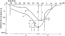
图2是一个图解表示,它表示了具有图1(A)及1(B)所示的旋转提线杆及一全旋转梭子的工业用锯齿形锁缝缝纫机的一条旋转提线杆运动曲线A及一条梭子运动曲线B;Figure 2 is a diagrammatic representation of a rotary thread lever movement curve A for an industrial zigzag lockstitch sewing machine having the rotary thread lever shown in Figures 1(A) and 1(B) and a fully rotary shuttle and a shuttle motion curve B;
图3是一示意图,它表示了在图2中的a时刻,旋转提线杆及面线的状态;Fig. 3 is a schematic diagram, which shows the state of rotating the thread take-up lever and the upper thread at the moment a in Fig. 2;
图4是一示意图,它表示了在图2中的b时刻,旋转提线杆及面线的状态;Fig. 4 is a schematic diagram, which shows the state of rotating the thread-lifting lever and the upper thread at moment b in Fig. 2;
图5是一示意图,它表示了在图2中的c时刻,旋转提线杆及面线的状态;Fig. 5 is a schematic diagram, which shows the state of rotating the thread take-up lever and the upper thread at moment c in Fig. 2;
图6(A)是一平面图,它表示了一种传统式旋转提线杆,而图6(B)则是沿图6(A)中b-b线所作的剖视图;Fig. 6 (A) is a plane view, and it has represented a kind of traditional rotary thread take-up lever, and Fig. 6 (B) is the sectional view that is done along b-b line among Fig. 6 (A);
图7是一个图解表示,它表明了具有图6(A)及6(B)所示的传统式旋转提线杆及一全旋转梭子的工业用锯齿形锁缝缝纫机的一条旋转提线杆运动曲线和一条梭子的运动曲线;Figure 7 is a diagrammatic representation showing the motion of a rotary thread lifter for an industrial zigzag lockstitch sewing machine having the conventional rotary thread lifter shown in Figures 6(A) and 6(B) and a fully rotary shuttle curves and a shuttle's motion curve;
图8是一示意图,它表示了在图7中的a时刻,旋转提线杆及面线的状态;以及Fig. 8 is a schematic diagram showing the state of rotating the thread lifting lever and the upper thread at a moment in Fig. 7; and
图9是一示意图,它表示了在图7中的b时刻,旋转提线杆及面线的状态。Fig. 9 is a schematic diagram showing the state of rotating the thread-lifting lever and the upper thread at moment b in Fig. 7 .
图10(A)和图10(B)表示本发明的另一个实施例。10(A) and 10(B) show another embodiment of the present invention.
下面将结合附图对本发明的一种缝纫机旋转提线杆进行说明。A rotary thread lifting lever of a sewing machine according to the present invention will be described below in conjunction with the accompanying drawings.
本发明的旋转提线杆大致如图1(A)所示,在图1(A)中,旋转提线杆1包括一个旋转提线杆元件5,该元件由一个基体部3及一个从该基体部3伸出的臂部4。具体说,该基体部3是固定在一旋转元件2上的,该元件沿一个方向环绕一个水平轴线旋转,所述的水平轴线与该缝纫机的心轴,例如一根驱动曲柄轴的针杆相联系,臂部4从基体部3相对旋转轴线向外延伸出来。The rotary thread lifting lever of the present invention is generally shown in Figure 1 (A), in Figure 1 (A), the rotary thread lifting lever 1 comprises a rotating thread
提线杆元件5的基体部3是平坦的,且大致为半圆形,它具有三个带螺纹的孔眼,用来将该提线杆元件5固定到旋转元件2上。臂部4从基体部半圆形的弦部伸出。如图1(B)所示,借助于固定安装在旋转元件2上的基体部3,使臂部4沿旋转元件2的轴向向外偏移、从而相对旋转元件2形成一个间隙。臂部4的外端部稍向内弯曲,然后一直向外延伸,然后构成一承线部7。该承线部7包括弧形的锁定抓手8和9,沿提线杆的旋转方向看,该抓手是从臂部4的自由端向前,然后再反向延伸。The
该旋转提线杆1是顺时针转动的。当面线环绕着提线杆1的臂部4形成单一的线圈时(如图3至5所示),即可进行一个提线动作;也就是说,如此形成的线圈沿臂的后缘10及前缘11作向后及向前的滑动,以便将线提起。在旋转提线杆1的转动过程中,通过臂部4自由端的锁定抓手8和9以及通过基体3二端的突出部12和13,可以防止线圈从臂部落下。This rotary thread take-up lever 1 rotates clockwise. When the upper thread forms a single loop around the
上述旋转提线杆的结构大致与传统式的相类似,然而应当提请注意的是,本发明的旋转提线杆1是这样设计的:与传统式旋转提线杆相类似,其承线点14及15被设置在支承着面线的臂部4的前、后缘11和10上。承线点14和15支承着最大供应量的线。臂部4的前缘11上的承线点14的旋转半径R1(即旋转中心O与承线点14间的距离)与传统式的相等,但是臂部后缘10上的承线点15的旋转半径R2(即旋转中心与承线点15间的距离)却要小于传统旋转提线杆中的半径。而且有一部位10b从臂的后缘10上的承线点15处延伸出来,伸向锁定抓手9,沿旋转方向C看,该部位10b稍微有些向后倾斜。The structure of the above-mentioned rotary thread take-up lever is roughly similar to the traditional one, but it should be noted that the rotary thread take-up lever 1 of the present invention is designed in this way: similar to the traditional rotary thread take-up lever, its
现参照附图1至5,对上述结构的旋转提线杆的操作进行说明。Now with reference to accompanying drawings 1 to 5, the operation of the rotating thread take-up lever of the above-mentioned structure is described.
图2是一种图解表示,它表示了具有上述结构的本发明旋转提线杆1及一全旋转梭子的工业用锯齿形锁缝缝纫机的提线杆运动曲线A及梭子运动曲线B,S和P分别表示供应面线和向上提拉面线的时段。图3,4和5分别示出了在图2中a、b、c时刻旋转提线杆及面线的状态。Fig. 2 is a kind of diagram representation, and it has represented the thread take-up lever movement curve A and the shuttle movement curve B, S and P represents the periods of supplying noodle thread and lifting noodle thread, respectively. Figures 3, 4 and 5 respectively show the state of rotating the thread take-up lever and the upper thread at moments a, b and c in Fig. 2 .
在图2中的a时刻,面线被支承在臂部4后缘10的承线点15处,如图3所示。在这种情况下,当旋转提线杆1进一步转动,面线便被支承在臂14的前、后缘11和10的二个承线点14和15上。在图2的b时刻,线作最大的供应,如图4所示。At moment a in FIG. 2 , the upper thread is supported at the
在这种情况下(图4),当旋转提线杆1再继续转动,处于图2中的c时刻,则面线被支承在臂4的前缘11上的承线点4处,如图5所示。这样,面线就被上拉,同时支承在承线点14处。In this case (Fig. 4), when the rotating thread take-up lever 1 continues to rotate, at moment c in Fig. 2, the upper thread is supported at the
在图2的a与c之间的时间区间内,面线16被支承在后缘10及前缘11的承线点14和15上。这时,由于后缘10上承线点15与旋转中心O之间的距离R2(即承线点15的旋转半径)要小于传统式旋转提线杆的距离,由旋转提线杆1供给的上线16的最大长度M也就小于由传统提线杆供给的长度,自然也对小于废线的最大长度D。In the time interval between a and c of FIG. 2 , the
承线点15在臂4的后缘10上是如此定位的,即当面线被支承在臂4的前缘11上的承线点14上时,如图5所示,位于承线点14与供线源T之间的那部分面线不应当松驰下来。这样,面线16脱出梭子所需的废线长度E并未改变,只是废线的最大长度D被有效的减小了。The thread-
在本发明的旋转提线杆1中,如上所述,从臂后缘10上的承线点15伸向锁定抓手9的部位10b,沿旋转方向看去略微向后倾斜,这一特征可以防止在图2的a时刻之后,当旋转提线杆1进一步转动时,面线突然的放松(与图7中F点所指示的相比)。In the rotating thread lifting lever 1 of the present invention, as mentioned above, the
如上所述,在旋转线杆将面线支承在二个点上的那段时间内(即图2中的a与c时刻之间),废线的长度减小了,而且可以防止面线的突然松驰。这一特征基本上可以消除传统式提线杆中所存在的问题,即当缝纫机高速运行时,缝纫线容易产生不稳定的运动,从而造成不规整的线迹,以及有可能产生断线。As mentioned above, during the period when the rotating rod supports the upper thread at two points (i.e. between a and c moments in Fig. 2), the length of the waste thread is reduced, and the upper thread can be prevented from being broken. Suddenly relax. This feature basically eliminates the problems of conventional thread lifters, that is, when the sewing machine is running at high speed, the sewing thread is prone to erratic movement, resulting in irregular stitches and possible thread breakage.
下面将参照附图10(A)及10(B)对另一个实施例进行说明。Another embodiment will be described below with reference to Figs. 10(A) and 10(B).
在面线被缝纫机的切刀切断之后,旋转提线杆1转动期间,有可能使切断之后的线被提线杆抓住,并将之缠住。这时,随着提线杆的转动,它将继续将线从梭心中拉出。为了切断如此缠绕在提线杆1上的面线,臂部4上设有一个长孔18,而且在该长孔18内设有一把刀具。该长孔18以及刀具都相对于半径的方向朝外定位。After the upper thread is cut off by the cutting knife of the sewing machine, during the rotation of the rotary thread take-up lever 1, the cut thread may be caught by the thread take-up lever and entangled. At this time, as the thread take-up lever turns, it will continue to pull the thread out of the bobbin. In order to cut the upper thread thus wound on the thread take-up lever 1, an
最好在后缘10的承线点15附近设置一个突起部17,它相对于半径方向向内突起。如图10(A)所示,该突起部17可以防止由切具切断后的面线相对于半径方向向内引到臂部4,这样,即使这样切断后的面线缠绕在提线杆1的臂部4上,切刀也可以确保将缠绕在其上的面线切断。Preferably, near the thread-carrying
在该实施例中,后缘10上的承线点15的旋转半径R2要小于前缘11上的承线点14的旋转半径R1。In this embodiment, the radius of rotation R 2 of the
在该实施例中,臂部4的形状大致如同一平板。也就是说,臂4的外端部不带有弯曲部,弧形的锁定抓手8和9自臂4的自由端向前然后再反向延伸(沿旋转方向C看)。In this embodiment, the
现已参照附图对本发明进行了说明,但应当注意,本发明并不局限于此。例如,臂4的长度及构形,以及前、后缘11及10上的承线点14及15的旋转半径R1及R2,都是可根据所使用的梭子的特点而进行变化的。The present invention has been described with reference to the accompanying drawings, but it should be noted that the present invention is not limited thereto. For example, the length and configuration of the
借助于本发明的旋转提线杆,可满足面线16从梭子中脱出所需要的废线的长度保持不变,而仅仅减小了由提线杆所供给的最大线长。这一特点基本上消除了传统式提线杆所存在的问题,即当缝纫机高速运转时,缝纫线容易产生不稳定的运动,从而造成不规整的线迹以及断线。By means of the rotating thread lifting lever of the present invention, the length of the waste thread required to satisfy the need for the
Claims (3)
Applications Claiming Priority (2)
| Application Number | Priority Date | Filing Date | Title |
|---|---|---|---|
| JP302433/94 | 1994-12-06 | ||
| JP6302433A JP2738821B2 (en) | 1994-12-06 | 1994-12-06 | Sewing machine balance |
Publications (2)
| Publication Number | Publication Date |
|---|---|
| CN1132806A CN1132806A (en) | 1996-10-09 |
| CN1052768C true CN1052768C (en) | 2000-05-24 |
Family
ID=17908873
Family Applications (1)
| Application Number | Title | Priority Date | Filing Date |
|---|---|---|---|
| CN95121781.XA Expired - Lifetime CN1052768C (en) | 1994-12-06 | 1995-12-06 | Rotary thread takeup lever in sewing machine |
Country Status (3)
| Country | Link |
|---|---|
| US (1) | US5555830A (en) |
| JP (1) | JP2738821B2 (en) |
| CN (1) | CN1052768C (en) |
Families Citing this family (3)
| Publication number | Priority date | Publication date | Assignee | Title |
|---|---|---|---|---|
| JP4230330B2 (en) * | 2003-10-14 | 2009-02-25 | Juki株式会社 | sewing machine |
| JP2006061225A (en) * | 2004-08-25 | 2006-03-09 | Brother Ind Ltd | Sewing machine balance |
| CN107700091A (en) * | 2016-03-07 | 2018-02-16 | 吴金玉 | A kind of anticreep line sewing machine with swing arm |
Family Cites Families (3)
| Publication number | Priority date | Publication date | Assignee | Title |
|---|---|---|---|---|
| US739158A (en) * | 1903-04-08 | 1903-09-15 | Singer Mfg Co | Take-up device for sewing-machines. |
| US2636464A (en) * | 1950-10-11 | 1953-04-28 | Singer Mfg Co | Rotary take-up for sewing machines |
| DE1218858B (en) * | 1958-03-21 | 1966-06-08 | Singer Co | Circumferential thread feeder for lockstitch sewing machines |
-
1994
- 1994-12-06 JP JP6302433A patent/JP2738821B2/en not_active Expired - Fee Related
-
1995
- 1995-12-06 CN CN95121781.XA patent/CN1052768C/en not_active Expired - Lifetime
- 1995-12-06 US US08/568,418 patent/US5555830A/en not_active Expired - Lifetime
Also Published As
| Publication number | Publication date |
|---|---|
| US5555830A (en) | 1996-09-17 |
| CN1132806A (en) | 1996-10-09 |
| JPH08155171A (en) | 1996-06-18 |
| JP2738821B2 (en) | 1998-04-08 |
Similar Documents
| Publication | Publication Date | Title |
|---|---|---|
| CN1806075A (en) | Sequin needle sewing device | |
| CN1052768C (en) | Rotary thread takeup lever in sewing machine | |
| CN1093898C (en) | Sewing machine having multiple needles | |
| CN1147635C (en) | Assembly for controlling yarn tension, bobbin case assembly and method for releasing yarn | |
| CN1117897C (en) | Oscillating shuttle of sewing machine | |
| CN1950556A (en) | Rotary shuttle device for sewing machine | |
| CN1115811A (en) | Bottom thread end clamping device in sewing machine | |
| CN1250789C (en) | Fuzz control device | |
| JPS5841266B2 (en) | Transfer tail winding device in open-end spinning machine | |
| CN1358895A (en) | Threading regualtor for sewing machine | |
| JPH05193832A (en) | Bobbin roll pipe receiver | |
| CN1518867A (en) | Reel master of spinning reel | |
| CN1056428C (en) | Vertically fully rotating hook | |
| CN1226295A (en) | Rotary hook device for sewing machines and machines incorporating same | |
| CN1190539C (en) | Horizontal shuttle opening device | |
| JP2000095439A (en) | Wire rod terminal end tying method for bobbin and device used therefor | |
| CN1236034A (en) | Thread cutter for sewing machine | |
| KR100665307B1 (en) | Sequin feeder | |
| JP4106146B2 (en) | Lower thread winding device | |
| JPS6037105Y2 (en) | Lower thread control device in sewing machine | |
| CN1517470A (en) | Thread rewinding device for sewing machine | |
| CN1380458A (en) | Double-lock type stitch sewing machine with rotation-proofing device for bobbin case | |
| JPH0643563Y2 (en) | Moving device of moving body | |
| JPH11104385A (en) | Half-turn shuttle drive of sewing machine | |
| JPS62292190A (en) | Reeling device for looper thread of sewing machine |
Legal Events
| Date | Code | Title | Description |
|---|---|---|---|
| C06 | Publication | ||
| PB01 | Publication | ||
| C10 | Entry into substantive examination | ||
| SE01 | Entry into force of request for substantive examination | ||
| C14 | Grant of patent or utility model | ||
| GR01 | Patent grant | ||
| CX01 | Expiry of patent term |
Granted publication date: 20000524 |
|
| EXPY | Termination of patent right or utility model |