The present application claims priority from us provisional patent application No.62/640,009 entitled "VISUAL TRACKING OF PERIPHERAL DEVICES" (VISUAL TRACKING OF peripheral device) filed on 7.3.2018 and us provisional patent application No.62/640,299 entitled "VISUAL TRACKING OF PERIPHERAL DEVICES" (VISUAL TRACKING OF peripheral device) filed on 7.3.2018, the entire disclosures OF which are hereby incorporated by reference as if fully set forth herein for all purposes.
Detailed Description
In conventional Virtual Reality (VR) or Augmented Reality (AR) systems, six degrees of freedom tracking of peripherals is achieved by including a series of electromagnetic sensors and emitters strategically placed on the user's AR headset, belt pack, and/or other auxiliary devices (e.g., totems, haptic devices, game tools, etc.). Typically, an electromagnetic tracking system includes at least one electromagnetic field emitter and at least one electromagnetic field sensor. Since the emitted electromagnetic field has a known distribution, the detected field can be analyzed to determine the location and/or orientation of the peripheral device. While such systems provide a simple solution to the positioning problem, there is a need for additional solutions that provide higher accuracy positioning. Embodiments of the present invention may replace or supplement electromagnetic tracking systems.
Embodiments of the present invention provide a visual tracking system for performing high precision positioning of a handheld device (e.g., totem) relative to a wearable device (e.g., a head-mounted device). An imaging device is mounted on one of the devices and can capture images of one or more fiducials fixed to the other device. Additional imaging devices may be mounted on the handheld device to capture various environmental markers. Based on the number of fiducials in the captured image, different data processing schemes may be implemented that utilize the fiducial data (i.e., data with local references based on the fiducial image) and the handheld data (data with world references collected from sensors mounted on the handheld device) differently. Each data processing scheme, referred to herein as an operating state, enables accurate estimation of the position and/or orientation of the handheld device relative to the wearable device. The tracking system may inform the AR system of the estimated location, and the AR system may use the location information to generate virtual content that is comfortable for the user.
Fig. 1 shows an AR scene viewed by a wearable AR device according to embodiments described herein. An AR scene 100 is depicted in which a user of AR technology sees a real-world park-like setting 106 featuring people, trees, buildings in the background, and a concrete platform 120. In addition to these items, the user of AR technology also perceives that he "sees" a robotic statue 110 standing on a real world platform 120, as well as a flying cartoon-style avatar character 102 that appears to be the avatar of bumblebee, even though these elements (character 102 and statue 110) are not present in the real world. Because the human visual perception and nervous system are extremely complex, it is challenging to produce VR or AR techniques that facilitate comfortable, natural-feeling, rich presentation of virtual image elements in addition to other virtual or real-world image elements.
Figure 2 shows various possible components of an AR system. In the illustrated embodiment, an AR system user 260 is shown wearing a head-mounted component 258 featuring a frame 264 structure coupled to a display system 262 positioned in front of the user's eyes. Speaker 266 is coupled to frame 264 in the configuration shown and is positioned near the ear canal of the user (in one embodiment, another speaker, not shown, is positioned near another ear canal of the user to provide stereo/shapeable sound control). The display 262 is operatively coupled (as shown at 268) to a local processing and data module 270, such as by a wired lead or wireless connection, and the local processing and data module 270 may be mounted in various configurations, such as fixedly attached to the frame 264, fixedly attached to a helmet or hat, removably attached to the torso of the user 260 in a backpack configuration, or removably attached to the hip of the user 260 in a belt-coupled configuration.
The local processing and data module 270 may include a power efficient processor or controller, and digital memory (such as flash memory), both of which may be used to assist in processing, caching, and storing the following data: a) data captured from sensors operatively coupled to the frame 264, including, for example, an image capture device (such as a camera), a microphone, an inertial measurement unit, an accelerometer, a compass, a GPS unit, a radio, and/or a gyroscope; and/or b) data acquired and/or processed using remote processing module 272 and/or remote data repository 274, which may be transferred to display 262 after such processing or retrieval.
Local processing and data module 270 is operatively coupled (as shown by wired or wireless communication links) to remote processing module 272 and remote data repository 274, such as by wired or wireless communication links, so that these remote modules 272, 274 are operatively coupled to each other and available as resources to local processing and data module 270. In one embodiment, remote processing module 272 may include one or more relatively powerful processors or controllers configured to analyze and process data and/or image information. In one embodiment, remote data repository 274 may include a relatively large-scale digital data storage facility, which may be available through the internet or other network configuration in a "cloud" resource configuration. In one embodiment, all data is stored and all calculations are performed in the local processing and data module, allowing for fully autonomous use from any remote module.
Fig. 3 shows an example of how a visual tracking system may be incorporated into an AR system having a wearable device 302 (e.g., a headset) and a handheld device 304 (e.g., a controller). In some embodiments, the handheld device 304 may be a handheld controller that allows a user to provide input to the AR system. For example, the handheld device 304 may be a totem used in a game scene. The handheld device 304 may be a haptic device and may include one or more haptic surfaces that utilize various sensor types. During operation of the AR system, the user may hold the handheld device 304 in his/her left or right hand by actively gripping the handheld device 304 and/or by securing an attachment means (e.g., a wrap strap) to the user's hand.
The handheld device 304 may include one or more fiducials (referred to herein as handheld fiducials 322) positioned along one or more external surfaces of the handheld device 304 such that the fiducials may be located within a field of view of the imaging device external to the handheld device. The handheld fiducial points 322 may have a known relationship to each other such that the imaging device may determine its position and/or orientation relative to the handheld device 304 by capturing images of one or more of the handheld fiducial points 322. The hand held reference points 322 may be dynamic, static, powered, unpowered, and in some embodiments may be distinguished from one another. For example, the first reference point may be a Light Emitting Diode (LED) having a first wavelength, and the second reference point may be an LED having a second wavelength. Alternatively or additionally, different reference points may have different brightness and/or may pulse at different frequencies (e.g., a first reference point may pulse at 100Hz and a second reference point may pulse at 150 Hz).
The handheld device 304 may include one or more imaging devices (referred to herein as handheld imaging devices 326) positioned such that when the handheld device 304 is held by a user, certain features around the handheld device 304 and/or the wearable device 302 are within the field of view of the imaging devices. For example, the front handheld imaging device 326A may be positioned such that its field of view is oriented away from the user toward one or more features in the surrounding environment of the handheld device 304, and the rear handheld imaging device 326B may be positioned such that its field of view is oriented toward the wearable device 302. The handheld imaging device 326 may include one or more forward facing imaging devices and/or one or more rearward facing imaging devices to produce the desired cumulative field of view. In some embodiments, the handheld imaging device 326 may be an optical device such as a camera, and may capture still or moving images.
The handheld device 304 may include an Inertial Measurement Unit (IMU) (referred to herein as the handheld IMU324) that is rigidly fixed within the handheld device 304 such that rotational and linear motions of the handheld device 304 are similarly experienced by the handheld IMU 324. In some cases, the handheld IMU324 may include one or more accelerometers (e.g., three), one or more gyroscopes (e.g., three), one or more magnetometers (e.g., three), and/or digital signal processing hardware and software to convert raw measurements into processed data. For example, the handheld IMU324 may include an accelerometer, a gyroscope, and a magnetometer for each of the three axes. For each axis, the handheld IMU324 may output one or more of: linear position, linear velocity, linear acceleration, rotational position, rotational velocity, and/or rotational acceleration. Alternatively or additionally, the handheld IMU324 may output raw data from which any of the forms of processed data described above may be calculated.
The handheld device 304 may include a rechargeable and/or replaceable battery 328 or other power source to power the handheld reference point 322, the handheld imaging device 326, the handheld IMU324, and any other components of the handheld device 304. Although not shown in fig. 3, the handheld device 304 may include circuitry for enabling wireless communication with the wearable device 302 and/or the belt pack 340. For example, upon detecting or capturing data using the handheld imaging device 326 and the handheld IMU324, the handheld device 304 may transmit the raw or processed data to the wearable device 302 and/or the belt pack 340.
The wearable device 302 may include one or more fiducials (referred to herein as wearable fiducials 306) positioned along one or more external surfaces of the wearable device 302 such that the fiducials may be located within the field of view of the rear handheld imaging device 326B. The wearable fiducials 306 may have a known relationship with respect to each other such that the imaging device may determine its position and/or orientation with respect to the wearable device 302 by capturing images of one or more wearable fiducials 306. In some embodiments, the wearable fiducials 306 may be dynamic, static, electrical, unpowered, and may be distinguished from one another. For example, the first reference point may be an LED having a first wavelength, and the second reference point may be an LED having a second wavelength. Alternatively or additionally, different reference points may have different brightness and/or may pulse at different frequencies.
The wearable device 302 may include one or more imaging devices (referred to herein as wearable imaging devices 310) positioned such that when the user holds the handheld device 304, and in particular the handheld fiducial point 322, is within the field of view of the imaging device. For example, one or more wearable imaging devices 310 may be positioned on the wearable device 302 facing forward, above, below, and/or to the side of the optical see-through component of the wearable device 302. In one embodiment, two wearable imaging devices 310 may be positioned on opposite sides of the optical see-through component of wearable device 302. In some embodiments, wearable imaging device 310 may be an optical device such as a camera, and may capture still or moving images.
The wearable device 302 may include an IMU (referred to herein as a wearable IMU 308) that is rigidly secured within the wearable device 302 such that rotational and linear motions of the wearable device 302 are similarly experienced by the wearable IMU 308. In some cases, the wearable IMU308 may include one or more accelerometers (e.g., three), one or more gyroscopes (e.g., three), one or more magnetometers (e.g., three), and/or digital signal processing hardware and software to convert raw measurements into processed data. For example, the wearable IMU308 may include an accelerometer, a gyroscope, and a magnetometer for each of the three axes. For each axis, the wearable IMU308 may output one or more of: linear position, linear velocity, linear acceleration, rotational position, rotational velocity, and/or rotational acceleration. Alternatively or additionally, wearable IMU308 may output raw data from which any of the forms of processing data described above may be calculated.
In some embodiments, the AR system may include a belt pack 340, which may include a computing device (e.g., one or more processors and associated memory) for performing positioning of the handheld device 304 relative to the wearable device 302. Alternatively or additionally, the computing apparatus may reside in the wearable device 302 itself, or even in the handheld device 304. The computing apparatus may receive raw or processed data from each of the wearable IMU308, the wearable imaging device 310, the handheld IMU324, and the handheld imaging device 326 (via wired and/or wireless connections), and may compute a geospatial location of the handheld device 304 (relative to a geospatial location of the wearable device 302) and an orientation of the handheld device 304 (relative to an orientation of the wearable device 302). In one or more embodiments, the computing device may, in turn, include a mapping database 342 (e.g., a transferable world model, coordinate space, etc.) to detect gestures, determine coordinates of real and virtual objects, and may even be connected to cloud resources and the transferable world model. In some embodiments, images captured using the wearable imaging device 310 and/or the handheld imaging device 326 may be used to build a transferable world model. For example, features may be detected in the captured images, and the collected data (e.g., sparse points) may be used to construct a deliverable world model or environmental map.
Fig. 4 shows a diagram of a positioning task performed by an AR system, in which the position and orientation of a handheld device 304 relative to a wearable device 302 is determined. In the illustrated diagram, wearable device 302 has a geospatial location ("wearable location") and an orientation ("wearable orientation") defined as (X) relative to a world referenceWP,YWP,ZWP) The orientation is defined relative to the world reference as (X)WO,YWO,ZWO). In some cases, the geospatial location of wearable device 302 is represented in longitude, latitude, and elevation values, and the orientation of wearable device 302 is represented in pitch, yaw, and roll values.
As shown, the handheld device 304 has a geospatial position (X) relative to the wearable device 302WP,YWP,ZWP) Is defined as (X'HP,Y'HP,Z'HP) And an orientation (X) relative to the wearable device 302 (a "handheld location")WO,YWO,ZWO) Is defined as (X'HO,Y'HO,Z'HO) Is "hand-held orientation"). In some cases, the geospatial position of the handheld device 304 is represented in X, Y, and Z cartesian values, and the orientation of the handheld device 304 is represented in pitch, yaw, and roll values. As one particular example, when the user holds the handheld device 304, the geospatial position of the handheld device 304 may be equal to (0.7m, -0.5m, 0.1m) and the orientation of the handheld device 304 may be equal to (10.2 °, -46.2 °, 15.2 °).
Fig. 5 shows an example configuration of an AR system 500 in which wearable device 302 includes one or more wearable fiducials 306 and handheld device 304 includes one or more rearward handheld imaging devices 326, the field of view of rearward handheld imaging devices 326 at least partially and at least temporarily including wearable fiducials 306 when the user is holding handheld device 304 in normal operation. The AR system 500 may include additional sensors, such as a handheld IMU324, mounted on the handheld device 304. One advantage of this configuration may be that the handheld device 304 has all the data needed to perform its own positioning with respect to the wearable device 302, thereby reducing the processing load on the wearable device 302. AR system 500 may include additional sensors mounted on wearable device 302, such as wearable IMU 308.
Fig. 6 illustrates a method 600 of performing positioning of a handheld device 304 relative to a wearable device 302 using AR system 500. One or more steps of the method 600 may be omitted or may be performed in a different order than the illustrated embodiment, and one or more steps of the method 600 may be performed at one or more processing devices located within the wearable device 302, the handheld device 304, and/or the belt pack 340.
At step 602, an image ("fiducial image") is captured by the handheld imaging device 326. The fiducial image may contain several of the wearable fiducials 306. For example, if there are three wearable fiducials 306, the fiducial image may be analyzed to determine whether it contains zero, one, two, or three fiducials.
At step 604, the position and/or orientation of the handheld device 304 relative to the wearable device 302 is calculated, for example, based on the fiducial point image. For example, the fiducial image may be analyzed to determine the location of any of the wearable fiducials 306, and the location and/or orientation may be determined based on the locations of the fiducials within the fiducial image and the known physical relationship between the wearable fiducials 306. The position and/or orientation of the handheld device 304 may be used to determine the pose of the handheld device 304 with respect to the wearable device 302. The output of step 604 is referred to as reference data 630.
At step 610, data indicative of at least rotational motion of the handheld device 304 relative to the world (and/or relative to the wearable device 302) ("IMU data") is detected by the handheld IMU 324. The IMU data may include the rotational speed or raw data from which the rotational speed is calculated. In some embodiments, the IMU data is also indicative of linear motion of the handheld device 304, and may include linear acceleration or raw data from which linear acceleration is calculated.
At step 612, the position and/or orientation of the handheld device 304 is calculated based on the IMU data. In some embodiments, the position and/or orientation of the handheld device 304 relative to the world is calculated (using a previously known and/or estimated orientation relative to the world), and/or in some other embodiments, the position and/or orientation of the handheld device 304 relative to the wearable device 302 is calculated (using a previously known and/or estimated orientation relative to the wearable device 302).
At step 614, a position and/or orientation of the handheld device 304 relative to the wearable device 302 is calculated based on the baseline data 630 and/or the handheld data 632. The fiducial data 630 may include the fiducial point image and/or the position and/or orientation calculations performed in step 604 based on the fiducial point image. The handheld data 632 may include IMU data and/or position and/or orientation calculations based on IMU data performed in step 612. The position and orientation calculation at step 614 may be performed according to one of various operating states based on the number of fiducial points found in the fiducial point image. Each operating state may process the baseline data 630 and the handheld data 632 differently and may emphasize one type of data over another. These operating states will be described in more detail with reference to fig. 13.
At step 616, the position and/or orientation of the handheld device 304 relative to the wearable device 302 is output to, for example, an external device and/or a process for operating the AR system 500. For example, the position and/or orientation may be output to the AR system 500 to generate and display virtual content.
Fig. 7 shows an example configuration of an AR system 700 in which wearable device 302 includes one or more wearable imaging devices 310, the field of view of wearable imaging devices 310 at least partially and at least temporarily includes a handheld fiducial point 322 and handheld device 304 includes one or more handheld fiducial points 322 when the user holds handheld device 304 in normal operation. The AR system 700 may include additional sensors, such as a handheld IMU324, mounted on the handheld device 304. One advantage of this configuration may be the simplicity and low power consumption of the handheld device 304. The AR system 700 may include additional sensors mounted on the wearable device 302, such as the wearable IMU 308.
Fig. 8 illustrates a method 800 of performing positioning of a handheld device 304 relative to a wearable device 302 using an AR system 700. One or more steps of the method 800 may be omitted or may be performed in a different order than the illustrated embodiment, and one or more steps of the method 800 may be performed at one or more processing devices located within the wearable device 302, the handheld device 304, and/or the belt pack 340.
At step 802, an image ("fiducial point image") is captured by wearable imaging device 310. The fiducial image may contain several of the handheld fiducials 322. For example, if there are three handheld fiducial points 322, the fiducial point image can be analyzed to determine that it contains zero, one, two, or three fiducial points.
At step 804, the position and/or orientation of the handheld device 304 relative to the wearable device 302 is calculated, for example, based on the fiducial point image. For example, the fiducial point images may be analyzed to determine the location of any of the handheld fiducial points 322, and the location and/or orientation may be determined based on the location of the fiducial points within the fiducial point images and the known physical relationship between the handheld fiducial points 322. The position and/or orientation of the handheld device 304 may be used to determine the pose of the handheld device 304 with respect to the wearable device 302. The output of step 804 is referred to as reference data 830.
At step 810, data indicative of at least rotational movement of the handheld device 304 relative to the world ("IMU data") is detected by the handheld IMU 324. The IMU data may include the rotational speed or raw data from which the rotational speed is calculated. In some embodiments, the IMU data is also indicative of linear motion of the handheld device 304, and may include linear acceleration or raw data from which linear acceleration is calculated.
At step 812, the position and/or orientation of the handheld device 304 is calculated based on the IMU data. In some embodiments, the position and/or orientation of the handheld device 304 relative to the world is calculated (using a previously known and/or estimated orientation relative to the world), and/or in some embodiments, the position and/or orientation of the handheld device 304 relative to the wearable device 302 is calculated (using a previously known and/or estimated orientation relative to the wearable device 302). The output of step 812 may be referred to as handheld data 832.
At step 814, the position and/or orientation of the handheld device 304 relative to the wearable device 302 is calculated based on the baseline data 830 and/or the handheld data 832. The fiducial data 830 may include the fiducial point image and/or the position and/or orientation calculations performed in step 804 based on the fiducial point image. The handheld data 832 may include IMU data and/or position and/or orientation calculations performed in step 812 based on the IMU data. The position and/or orientation calculation at step 814 may be performed according to one of various operating states based on the number of fiducial points found in the fiducial point image. Each operating state may process the baseline data 830 and the handheld data 832 differently and may emphasize one type of data more than the other. These operating states will be described in more detail with reference to fig. 13.
At step 816, the position and/or orientation of the handheld device 304 relative to the wearable device 302 is output to, for example, an external device and/or a process for operating the AR system 700. For example, the position and/or orientation may be output to the AR system 700 to generate and display virtual content.
Fig. 9 illustrates an example configuration of an AR system 900, wherein the handheld device 326 includes a front handheld imaging device 326A and a rear handheld imaging device 326B, the field of view of the front handheld imaging device 326A at least partially and at least temporarily including one or more surrounding features 344 when the user is holding the handheld device 304, and the field of view of the rear handheld imaging device 326B at least partially and at least temporarily including one or more wearable fiducials 306 when the user is holding the handheld device 304 in normal operation. In an example configuration, a plurality of wearable fiducials 322 are secured to the wearable device 302. The AR system 900 may include additional sensors, such as handheld IMU324, mounted on the handheld device 304. One advantage of this configuration may be the increased accuracy provided by multiple imaging devices. The AR system 900 may include additional sensors mounted on the wearable device 302, such as the wearable IMU 308.
Fig. 10 shows a method 1000 of performing positioning of a handheld device 304 relative to a wearable device 302 using an AR system 900. One or more steps of the method 1000 may be omitted or may be performed in a different order than the illustrated embodiment, and one or more steps of the method 1000 may be performed at one or more processing devices located within the wearable device 302, the handheld device 304, and/or the belt pack 340.
At step 1002, an image ("fiducial image") is captured by the rear handheld imaging device 326B. The fiducial image may contain several of the wearable fiducials 306. For example, if there are three wearable fiducials 306, the fiducial image may be analyzed to determine that it contains zero, one, two, or three fiducials.
At step 1004, the position and/or orientation of the handheld device 304 relative to the wearable device 302 is calculated, for example, based on the fiducial point image. For example, the fiducial image may be analyzed to determine the location of any of the wearable fiducials 306, and the location and/or orientation may be determined based on the locations of the fiducials within the fiducial image and the known physical relationship between the wearable fiducials 306. The position and/or orientation of the handheld device 304 may be used to determine the pose of the handheld device 304 with respect to the wearable device 302. The output of step 1004 is referred to as reference data 1030.
At step 1006, an image ("world image") is captured by the front handheld imaging device 326A. The world image may contain surrounding features 344.
At step 1008, the position and/or orientation of the handheld device 304 relative to the world is calculated based on the world image. In some cases, the world images are compared to previous world images to estimate motion of the handheld device 304 using visual ranging techniques, which may include performing feature detection in each world image to establish correspondence between the world images. The motion vector of the handheld device 304 that most closely corresponds to the motion of the detected feature in the world image may then be calculated. The output of step 1008 is referred to as handheld data 1032.
At step 1010, data indicative of at least rotational motion of the handheld device 304 relative to the world ("IMU data") is detected by the handheld IMU 324. The IMU data may include the rotational speed or raw data from which the rotational speed may be calculated. In some embodiments, the IMU data is also indicative of linear motion of the handheld device 304, and may include linear acceleration or raw data from which linear acceleration may be calculated.
At step 1012, the position and/or orientation of the handheld device 304 is calculated based on the IMU data. In some embodiments, the position and/or orientation of the handheld device 304 relative to the world is calculated (using a previously known and/or estimated orientation relative to the world), and/or in some embodiments, the position and/or orientation of the handheld device 304 relative to the wearable device 302 is calculated (using a previously known and/or estimated orientation relative to the wearable device 302). The output of step 1012 is referred to as handheld data 1032.
At step 1014, a position and/or orientation of the handheld device 304 relative to the wearable device 302 is calculated based on the fiducial data 1030 and/or the handheld data 1032. The fiducial data 1030 may include the fiducial point image and/or the position and/or orientation calculations performed in step 1004 based on the fiducial point image. The handheld data 1032 may include world images, world image based position and/or orientation calculations performed in step 1008, IMU data, and/or IMU data based position and/or orientation calculations performed in step 1012. The position and orientation calculation at step 1014 may be performed according to one of various operating states based on the number of fiducial points found in the fiducial point image. Each operating state may process the reference data 1030 and the handheld data 1032 differently and may emphasize one type of data over another. These operating states will be described in more detail with reference to fig. 13.
At step 1016, the position and/or orientation of handheld device 304 relative to wearable device 302 is output to, for example, an external device and/or a process for operating AR system 900. For example, the position and/or orientation may be output to the AR system 900 to generate and display virtual content.
Fig. 11A illustrates an example configuration of an AR system 1100A, wherein the wearable device 302 includes one or more wearable imaging devices 310, the field of view of the wearable imaging devices 310 at least partially and at least temporarily including the handheld reference point 322 when the user holds the handheld device 304 in normal operation, and wherein the handheld device 304 includes one or more handheld imaging devices 326, the field of view of the handheld imaging devices 326 at least partially and at least temporarily including the one or more surrounding features 344 when the user holds the handheld device 304 in normal operation. In the example configuration shown in FIG. 11A, a single handheld reference point 322 is affixed to the handheld device 304. The AR system 1100 may include additional sensors, such as handheld IMU324, mounted on the handheld device 304. Advantages of the configuration shown in FIG. 11A include increased accuracy provided by multiple imaging devices, and computational efficiency in calculating position and orientation while constrained by a single fiducial point position. AR system 1100A may include additional sensors mounted on wearable device 302, such as wearable IMU 308.
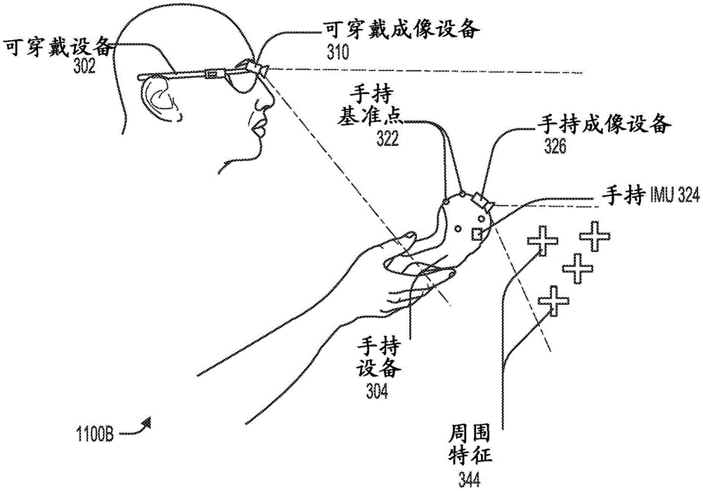
Fig. 11B shows an example configuration of an AR system 1100B, where the wearable device 302 includes one or more wearable imaging devices 310, the field of view of the wearable imaging devices 310 at least partially and at least temporarily including the handheld reference point 322 when the user holds the handheld device 304 in normal operation, and where the handheld device 304 includes one or more handheld imaging devices 326, the field of view of the handheld imaging devices 326 at least partially and at least temporarily including the one or more surrounding features 344 when the user holds the handheld device 304 in normal operation. In the example configuration shown in FIG. 11B, a plurality of handheld fiducials 322 are affixed to the handheld device 304. The AR system 1100B may include additional sensors, such as handheld IMU324, mounted on the handheld device 304. Advantages of such a configuration include increased accuracy provided by multiple imaging devices, and increased robustness through the combination of fiducial-based tracking and visual ranging techniques. AR system 1100B may include additional sensors, such as wearable IMUs, mounted on wearable device 302.
Fig. 12 illustrates a method 1200 of performing positioning of handheld device 304 relative to wearable device 302 using AR system 1100A of fig. 11A or AR system 1100B of fig. 11B. One or more steps of the method 1200 may be omitted or may be performed in a different order than the illustrated embodiment, and one or more steps of the method 1200 may be performed at one or more processing devices located within the wearable device 302, the handheld device 304, and/or the belt pack 340.
At step 1202, an image ("fiducial point image") is captured by wearable imaging device 310. The fiducial image may contain a number of handheld fiducials 322. For example, with respect to FIG. 11A, if there is one handheld fiducial 322, the fiducial image may be analyzed to determine that it contains zero or one fiducial. For example, with respect to FIG. 11B, if there are three handheld fiducial points 322, the fiducial point image can be analyzed to determine that it contains zero, one, two, or three fiducial points.
At step 1204, a position and/or orientation of the handheld device 304 relative to the wearable device 302 is calculated, for example, based on the fiducial point image. For example, with respect to fig. 11A, the fiducial point image may be analyzed to determine the location of the fiducial point, and the constraints on the location and/or orientation may be determined based on the fiducial point location within the fiducial point image. For example, with respect to fig. 11B, the fiducial image may be analyzed to determine the location of any fiducial, and the location and/or orientation may be determined based on the location of the fiducial within the fiducial image and the known physical relationship between the wearable fiducials 306.
At step 1206, an image ("world image") is captured by the handheld imaging device 326. The world image may contain surrounding features 344.
At step 1208, the position and/or orientation of the handheld device 304 relative to the world is calculated based on the world image. In some cases, the world images are compared to previous world images to estimate motion of the handheld device 304 using visual ranging techniques, which may include performing feature detection in each world image to establish correspondence between the world images. The motion vector of the handheld device 304 that most closely corresponds to the motion of the detected feature in the world image may then be calculated. The output of step 1208 is referred to as handheld data 1232.
At step 1210, data indicative of at least rotational motion of the handheld device 304 relative to the world ("IMU data") is detected by the handheld IMU 324. The IMU data may include the rotational speed or raw data from which the rotational speed may be calculated. In some embodiments, the IMU data is also indicative of linear motion of the handheld device 304, and may include linear acceleration or raw data from which linear acceleration may be calculated.
At step 1212, the position and/or orientation of the handheld device 304 is calculated based on the IMU data. In some embodiments, the position and/or orientation of the handheld device 304 relative to the world is calculated (using a previously known and/or estimated orientation relative to the world), and/or in some embodiments, the position and/or orientation of the handheld device 304 relative to the wearable device 302 is calculated (using a previously known and/or estimated orientation relative to the wearable device 302). The output of step 1212 is referred to as handheld data 1232.
At step 1214, the position and/or orientation of the handheld device 304 relative to the wearable device 302 is calculated based on the fiducial data 1230 and/or the handheld data 1232. For example, with respect to FIG. 11A, fiducial data 1230 may include the fiducial point image and/or constraints calculated based on the location and/or orientation of the fiducial point image performed in step 1204. For example, with respect to FIG. 11B, fiducial data 1230 may include a fiducial image and/or the position and/or orientation calculations performed in step 1204 based on the fiducial image. The handheld data 1232 may include the world image, the world image based position and/or orientation calculations performed in step 1208, the IMU data, and/or the IMU data based position and/or orientation calculations performed in step 1212. The position and orientation calculation at step 1214 may be performed according to one of various operating states based on the number of fiducial points found in the fiducial point image. Each operating state may process the reference data 1230 and the handheld data 1232 differently and may emphasize one type of data over another. These operating states will be described in more detail with reference to fig. 13.
At step 1216, the position and/or orientation of handheld device 304 relative to wearable device 302 is output to, for example, an external device and/or a process for operating AR system 1100. For example, the location and/or orientation may be output to the AR system 1100 to generate and display virtual content.
Fig. 13 shows a method 1300 of performing positioning of a handheld device 304 relative to a wearable device 302 using any one of AR systems 500, 700, 900, 1100, or any combination thereof. One or more steps of the method 1300 may be omitted or may be performed in a different order than the illustrated embodiment, and one or more steps of the method 1300 may be performed at one or more processing devices located within the wearable device 302, the handheld device 304, and/or the belt pack 340.
In step 1302, data indicative of motion of the handheld device 304 relative to the wearable device 302 is obtained using the imaging device ("baseline data"). Performing step 1302 may include performing one or both of steps 1304, 1306. At step 1304, an image containing a number of wearable fiducials 306 ("fiducial image") is captured by the rear handheld imaging device 326B. At step 1306, an image containing a number of handheld fiducials 322 ("fiducial image") is captured by wearable imaging device 310.
At step 1308, data indicative of at least rotational movement of the handheld device 304 relative to the world ("handheld data") is detected. Performing step 1308 may include performing one or both of steps 1310, 1312.
At step 1310, an image containing the surrounding feature 344 ("world image") is captured by the front handheld imaging device 326A. At step 1312, data indicative of at least rotational motion of the handheld device 304 relative to the world ("IMU data") is detected by the handheld IMU 324. The IMU data may include the rotational speed or raw data from which the rotational speed may be calculated. In some embodiments, the IMU data is also indicative of linear motion of the handheld device 304, and may include linear acceleration or raw data from which linear acceleration may be calculated.
At step 1314, the number of fiducial points included in the fiducial point image and the location (e.g., pixel location) of the observed fiducial point are determined.
At step 1316, the position and/or orientation of the handheld device 304 relative to the wearable device 302 is calculated/estimated/updated according to one of the three operating states. The operation state is selected based on the number of reference points observed in the reference point image. In the illustrated embodiment, a first operating state ("state 1") is selected when three or more fiducial points are observed in the fiducial point image, a second operating state ("state 2") is selected when one or two fiducial points are observed in the fiducial point image, and a third operating state ("state 3") is selected when zero fiducial points are observed in the fiducial point image. The switching between the states may occur each time a new fiducial point image is captured or at predetermined time intervals. For example, step 1316 may be performed at each camera frame based on one or both of fiducial data (e.g., fiducial point images) and handheld data (e.g., world images and IMU orientations). Step 1316 may further include prior position and/or orientation calculations to improve estimation accuracy.
From the first operating state ("state 1"), the position and/or orientation (full six degrees of freedom) can be calculated with high accuracy, for example, based on the reference data only. When four or more fiducials are observed, the position can be fully resolved. When exactly three fiducial points are observed, there are two possible position solutions, one of which may be discarded based on additional processing and/or comparison with previously calculated positions. In some embodiments, handheld data may be used to supplement and improve computational accuracy. In some embodiments, an extended kalman filter may be employed to improve accuracy based on previous position and/or orientation calculations.
From the second operational state ("state 2"), for example, both the reference data and the hand held data may be used to calculate the position and/or orientation. When two fiducial points are observed, the fiducial data enables computation of constrained position and/or orientation, and the handheld data can be used to complete the computation with the constraints imposed by the fiducial data. In some embodiments, an extended kalman filter may be employed to improve accuracy based on previous position and/or orientation calculations. The calculations performed in the second operating state may be less accurate overall than the calculations performed in the first operating state.
According to the third operational state ("state 3"), the position and orientation may be calculated, for example, based only on hand-held data (i.e., dead reckoning). In some embodiments, an extended kalman filter may be employed to improve accuracy based on previous position and/or orientation calculations. The calculations performed in the third operating state may be less accurate overall than the calculations performed in the first or second operating state.
At step 1318, IMU bias correction is performed to increase the accuracy of the IMU data provided as input at step 1316. Since IMU data may drift over time, periodic updates may recalibrate IMU data. In some embodiments, the bias update is provided only when the first operating state is selected, and a high accuracy bias update may be provided. In some embodiments, a bias update is provided when selecting either the first operating state or the second operating state, since both states utilize the reference data in their calculations. The offset update may be provided at each camera frame or at predetermined time intervals.
Fig. 14 illustrates a simplified computer system 1400 according to some embodiments described herein. FIG. 14 provides a schematic diagram of one example of a computer system 1400 that may perform some or all of the steps of the methods provided by various embodiments. It should be noted that FIG. 14 is intended merely to provide a general illustration of the various components, any or all of which may be suitably employed. Thus, fig. 14 broadly illustrates how various system elements may be implemented in a relatively separated or relatively more integrated manner.
Computer system 1400 is shown as including hardware elements that may be electrically coupled via bus 1405, or that may otherwise communicate as appropriate. These hardware elements may include: one or more processors 1410, including but not limited to one or more general purpose processors and/or one or more special purpose processors, such as digital signal processing chips, graphics acceleration processors, and/or the like; one or more input devices 1415, which may include, but are not limited to, a mouse, a keyboard, a camera, and/or the like; one or more output devices 1420, which may include, but are not limited to, a display device, a printer, and/or the like.
The computer system 1400 may further include and/or communicate with one or more non-transitory storage devices 1425, which storage devices 1425 may include, but are not limited to, local and/or network accessible memory, and/or may include, but is not limited to, disk drives, arrays of drives, optical storage devices, solid state storage devices, such as programmable, flash-updateable random access memory ("RAM") and/or read-only memory ("ROM"), and/or the like. Such storage devices may be configured to implement any suitable data storage, including but not limited to various file systems, database structures, and/or the like.
Computer system 1400 may also include a communication subsystem 1419, which may include, but is not limited to, a modem, a network card (wireless or wired), an infrared communication device, a wireless communication device, and/or a chipset, such as BluetoothTMDevices, 802.11 devices, WiFi devices, WiMax devices, cellular communications facilities, and the like. The communication subsystem 1419 may include one or more input and/or output communication interfaces to allow data to be exchanged with a network, such as the network described by way of example below, other computer systems, televisions, and/or any other devices described herein. Depending on the desired functionality and/or other implementation issues, a portable electronic device or the like may communicate images and/or other information via the communication subsystem 1419. In other embodiments, a portable electronic device, such as the first electronic device, may be incorporated into the computer system 1400, such as the electronic device that is the input device 1415. In some embodiments, computer system 1400 also includes a working memory 1435, which may include a RAM or ROM device as described above.
Computer system 1400 can also include software elements that are shown as being currently located within working memory 1435, working memory 1435 including operating system 1440, device drivers, executable libraries, and/or other code, such as one or more application programs 1445, which application programs 1445 can include computer programs provided by the various embodiments and/or can be designed to implement methods and/or configuration systems provided by other embodiments, as described herein. Merely by way of example, one or more of the procedures described with reference to the above-described methods may be embodied as code and/or instructions executable by a computer and/or a processor within a computer; in an aspect, then, such code and/or instructions may be used to configure and/or adapt a general purpose computer or other device to perform one or more operations in accordance with the described methods.
A set of these instructions and/or code may be stored on a non-transitory computer readable storage medium, such as the storage device 1425 described above. In some cases, the storage medium may be incorporated into a computer system, such as computer system 1400. In other embodiments, the storage medium may be separate from the computer system, e.g., a removable medium such as an optical disk, and/or provided in an installation package, such that the storage medium can be used to program, configure, and/or adapt a general purpose computer having the instructions/code stored thereon. These instructions may take the form of executable code that may be executed by computer system 1400, and/or may take the form of source code and/or installable code, which may then take the form of executable code when compiled and/or installed on computer system 1400, for example, using various commonly available compilers, installation programs, compression/decompression utilities, and so forth.
It will be apparent to those skilled in the art that substantial variations may be made in accordance with specific requirements. For example, customized hardware might also be used, and/or particular elements might be implemented in hardware and/or software including portable software (e.g., applets, etc.). In addition, connections to other computing devices, such as network input/output devices, may be employed.
As described above, in an aspect, some embodiments may employ a computer system, such as computer system 1400, to perform methods in accordance with various embodiments of the present technology. According to one set of embodiments, some or all of the processes of these methods are performed by computer system 1400 in response to processor 1410 executing one or more sequences of one or more instructions, which may be incorporated into operating system 1440 and/or other code contained in working memory 1435, such as application programs 1445. Such instructions may be read into working memory 1435 from another computer-readable medium, such as one or more storage devices 1425. By way of example only, execution of the sequences of instructions contained in the working memory 1435 may cause the processor 1410 to perform one or more processes of the methods described herein. Additionally or alternatively, portions of the methods described herein may be performed by dedicated hardware.
As used herein, the terms "machine-readable medium" and "computer-readable medium" refer to any medium that participates in providing data that causes a machine to operation in a specific fashion. In an embodiment implemented using computer system 1400, various computer-readable media may be involved in providing instructions/code to processor 1410 for execution and/or may be used to store and/or carry such instructions/code. In many implementations, the computer-readable medium is a physical and/or tangible storage medium. Such a medium may take the form of a non-volatile medium or a volatile medium. Non-volatile media includes, for example, optical and/or magnetic disks, such as the storage device 1425. Volatile media includes, but is not limited to, dynamic memory, such as the working memory 1435.
Common forms of physical and/or tangible computer-readable media include, for example, a floppy disk, a flexible disk, hard disk, magnetic tape, or any other magnetic medium, a CD-ROM, any other optical medium, punch cards, paper tape, any other physical medium with patterns of holes, a RAM, a PROM, an EPROM, a FLASH-EPROM, any other memory chip or cartridge, or any other medium from which a computer can read instructions and/or code.
Various forms of computer readable media may be involved in carrying one or more sequences of one or more instructions to processor 1410 for execution. By way of example only, the instructions may initially be carried on a magnetic and/or optical disk of a remote computer. The remote computer can load the instructions into its dynamic memory and send the instructions as signals over a transmission medium to be received and/or executed by the computer system 1400.
The communication subsystem 1419 and/or its components typically will receive signals, which the bus 1405 may then transfer to the working memory 1435, the processor 1410 retrieves and executes the instructions from the working memory 1435, and/or the data, instructions, etc., carried by the signals. The instructions received by the working memory 1435 may optionally be stored on the non-transitory storage device 1425 either before or after execution by the processor 1410.
The methods, systems, and devices discussed above are examples. Various configurations may omit, substitute, or add various procedures or components as appropriate. For example, in alternative configurations, the methods may be performed in an order different than that described, and/or various stages may be added, omitted, and/or combined. Also, features described for particular configurations may be combined in various other configurations. Different aspects and elements of the configuration may be combined in a similar manner. In addition, technology is being developed and thus many elements are examples and do not limit the scope of the disclosure or claims.
Specific details are given in the description to provide a thorough understanding of example configurations including embodiments. However, configurations may be practiced without these specific details. For example, well-known circuits, processes, algorithms, structures, and techniques have been shown without unnecessary detail in order to avoid obscuring the configurations. This description provides example configurations only, and does not limit the scope, applicability, or configuration of the claims. Rather, the foregoing description of the configurations will provide those skilled in the art with an enabling description for implementing the described techniques. Various changes may be made in the function and arrangement of elements without departing from the spirit or scope of the disclosure.
Further, the configuration may be described as a process, which can be depicted as a schematic flow chart diagram or a block diagram. Although each process may describe the operations as a sequential process, many of the operations can be performed in parallel or concurrently. In addition, the order of the operations may be rearranged. A process may have additional steps not included in the figures. Furthermore, examples of the methods may be implemented by hardware, software, firmware, middleware, microcode, hardware description languages, or any combination thereof. When implemented in software, firmware, middleware or microcode, the program code or code segments to perform the necessary tasks may be stored in a non-transitory computer-readable medium such as a storage medium. The processor may perform the described tasks.
Having described several example configurations, various modifications, alternative constructions, and equivalents may be used without departing from the spirit of the disclosure. For example, the above-described elements may be components of a larger system, where other rules may take precedence over or otherwise modify the application of the present technology. Also, many of the steps can be performed before, during, or after considering the above-described elements. Accordingly, the above description does not limit the scope of the claims.
As used herein and in the appended claims, the singular forms "a," "an," and "the" include plural referents unless the context clearly dictates otherwise. Thus, for example, reference to "a user" includes a plurality of such users, and reference to "the processor" includes reference to one or more processors and equivalents thereof known to those skilled in the art, and so forth.
Furthermore, the words "comprise," "comprising," "include," "including," "have," "contain," and "with" when used in this specification and the appended claims are intended to specify the presence of stated features, integers, components, or steps, but they do not preclude the presence or addition of one or more other features, integers, components, steps, acts, or groups thereof.
It is also understood that the examples and embodiments described herein are for illustrative purposes only and that various modifications or changes in light thereof will be suggested to persons skilled in the art and are to be included within the spirit and purview of this application and scope of the appended claims.