Detailed Description
Fig. 1 shows the successive steps of an embodiment of the method according to the invention for manufacturing a CMC part.
In step 10, the fiber structure intended to form the core of the fiber preform is obtained by three-dimensional weaving or by multilayer weaving.
"three-dimensional weaving" or "3D weaving" as used herein refers to a weaving method in which at least some of the warp yarns bind weft yarns to several weft yarn layers, such as "interlocking weaving". "interlocking weaving" refers herein to 3D weaving, in which each warp layer interconnects several weft layers, while all yarns in the same warp column have the same motion in the weaving plane.
"multi-layer weave" herein refers to a 3D weave having several layers of weft yarns, each layer of which is substantially identical to a conventional 2D fabric weave, such as a plain (canvas), satin, or twill type weave, but with certain points of the weave interconnecting the layers of weft yarns together.
The production of the fiber structure by 3D or multilayer weaving makes it possible to obtain a bond between the layers in a single weaving operation and therefore a good mechanical strength of the fiber structure and of the resulting composite part.
The fiber structure can be produced in a known manner by means of a jacquard-type weaving machine, on which a bundle of warp threads or strands is arranged in layers, the warp threads being bound by weft threads or strands which are likewise arranged in layers. Detailed embodiments of the production of fibre preforms intended to form a fibre reinforcement for aircraft engine blades from 3D woven fibre preforms are described in detail in documents US 7,101,154, US 7,241,112 and WO 2010/061140. Document US 2010/111678 discloses the manufacture of a fiber preform by three-dimensional weaving, which is used to form a complete CMC ring intended for use in a gas turbine.
The yarns or strands used to weave the core of the fiber preform may be made of ceramic fibers, for example substantially of silicon carbide SiC (hereinafter SiC fibers) or silicon nitride Si3N4The composition of the formed fibers. Specifically, a polycarbonate having a high degree of crystallinity, which is provided by Nippon Carbon company of Japan, may be usedThe yield strength is a yarn named "Hi-Nicalon", or preferably a yarn named "Hi-Nicalon Type-S". The yarns or strands used may also consist of carbon fibers.
In step 20, the fiber structure is shaped and its shape is maintained by a shaping tool to obtain a fiber preform core having a shape close to the shape of the part to be manufactured. An example of forming a fiber preform from a fiber structure can be found in particular in patent application US 2011/0293828.
The preform core is held in its forming tool, for example made of graphite, by chemical vapour infiltration or CVI to form, in a known manner, an embrittlement-release mesophase on the fibres of the preform core, made in particular of pyrolytic carbon or PyC or Boron Nitride (BN) or carbon, carbon or BC optionally doped with boron (5% to 20% boron, the remainder being carbon) (step 30). The thickness of the mesophase is preferably between 10nm and 1000 nm.
The parameters of the CVI process, in particular the temperature and pressure in the furnace, and the composition of the reactive vapor precursors of the mesophase material are chosen such that their deposition kinetics are limited, thereby promoting the diffusion of the vapor into the preform core and avoiding the occurrence of significant mesophase deposition thickness gradients in the thickness of the preform. For a given CVI process parameter, the deposition kinetics can be readily determined experimentally by measuring the thickness of the deposit formed on the surface of a control part (e.g., the entire SiC block), depending on the duration of the deposition phase. It can also be measured by correlating the thickness of the deposit as measured by optical or scanning electron microscopy on a polished cross section with the duration of the deposition phase.
For ceramic fibers, particularly SiC fibers, these fibers may optionally be surface treated prior to forming the interphase coating to remove the sizing agent and surface layer of oxides (e.g., silica SiO2) if present on the fibers.
In addition, after deposition of the mesophase, in particular the BN mesophase, and before formation of the matrix layer on the mesophase, a stable heat treatment of the mesophase may be carried out in a neutral atmosphere, for example under argon, without prior exposure of the mesophase to an oxidizing environment. Advantageously, the heat treatment is carried out in a CVI furnace immediately after the mesophase has been deposited. The purpose of the heat treatment is to chemically stabilize the mesophase material by degassing the volatile substances originating from the reactive gas phase present in the deposit and by eliminating the active sites present, to which oxygen can be bound, if the mesophase is exposed to an oxidizing environment during the use of the CMC part.
In step 40, the preform core is consolidated by a matrix phase or layer deposited by a gaseous (CVI) or liquid process. For the gaseous process, the preform core is held in a forming tool in a CVI furnace while a ceramic matrix layer is formed on the mesophase with CVI to consolidate the preform core, that is, to bond the preform fibers together sufficiently that the preform can retain its shape without the aid of the forming tool. The base layer is made of SiC, for example. The substrate layer may also be a layer of self-healing material comprising boron, such as a ternary Si-B-C system or boron carbide B4C capable of forming borosilicate-type glass with self-healing properties in the presence of oxygen. Reference may be made to documents US 5,246,736 and US 5,965,266, which describe how such self-healing layers or phases are obtained by CVI.
Liquid consolidation consists in impregnating the preform core with a liquid ceramic precursor and performing a thermal treatment of pyrolysis to convert the precursor into ceramic. The liquid ceramic precursor, in particular SiC, may be a Polycarbosilane (PCS) or Polytitanocarbosilane (PTCS) or Polysilazane (PSZ) type resin.
The thickness of the first matrix phase is at least equal to 500nm, preferably between 1 μm and 30 μm.
As mentioned above, the total thickness of the mesophase and matrix layers is chosen to sufficiently consolidate the fiber preform core, that is to say to bond the fibers of the preform core together sufficiently that the preform can be handled while retaining its shape without the aid of a retaining tool. The thickness may be at least equal to 500 nm. After consolidation, the preform core remains porous, e.g., the initial porosity is only partially filled by the mesophase and matrix layers.
Production of PyC, BC, B4C, Si-B-C, Si by CVI3N4Deposits of BN and SiC are known. Reference may be made specifically to US 5,246,736, US 5,738,951, US 5,965,266, US 6,068,930 and US 6,284,358.
It should be noted that the step of forming the interphase by CVI may be performed on the fibers of the fibrous structure prior to shaping of the fibrous structure, as long as the interphase is sufficiently thin without affecting the desired deformability of the fibrous structure.
After consolidation, the porous consolidated preform core is removed from the forming tool. If desired, the preform core may be machined (step 50) to the desired shape and size.
The next step (step 60) consists in dipping the preform core by Slurry Casting (SC) in a slurry containing at least one ceramic particle powder and one or more organic binders, such as water. The material of the particles may be selected from one of the following materials or a mixture of the following materials: SiC, silicon nitride or Si3N4SiC + C, boron carbide or B4C and titanium silicide or TiSi2. Once the preform core is impregnated, it is dried to remove the liquid phase (binder) from the slurry.
In parallel with steps 10 to 60 described above, the method comprises producing a pre-impregnated non-woven layer (step 70). More precisely, as shown in fig. 2, a bundle of continuous fibers 10 is unwound from a reel or drum 12. The fibers are for example SiC or carbon fibers. The fiber bundle 10 passes through a process chamber 14 in which process chamber 14 the continuous fibers are CVD coated with a layer of ceramic material, such as SiC, by chemical vapor deposition. The ceramic coating serves to protect the fibers during subsequent processing. The ceramic coating may be made of SiC or Boron Nitride (BN) alone or doped with silicon in order to improve oxidation resistance. After the coating is formed on the continuous fibers, the fiber bundle is passed through a vessel 16 containing carbon or ceramic precursor resin. For example, the liquid carbon precursor may be a resin with a relatively high coke content, such as a phenolic resin, while the liquid ceramic precursor, such as SiC, may be a Polycarbosilane (PCS) or a Polytitanocarbosilane (PTCS) or Polysilazane (PSZ) type resin. The fiber bundle is then wound onto a drum 18 to form a unidirectional pre-impregnated web. The web is then dried and removed from the drum. The web is cut into sections to form unidirectional prepregs. Each layer is cut according to the shape and size of the preform core part to be covered. The production of unidirectional prepregs is described in document US 2006/0043628.
The pre-impregnated nonwoven layer may also be formed from non-continuous fibers bonded into the layer by carbon or ceramic precursor resins.
The method continues with covering the preform core with one or more pre-impregnated non-woven layers obtained as described above (step 80). All or part of the outer surface of the preform core may be covered by a pre-impregnated non-woven layer. In the case where only a portion of the outer surface of the preform core should have a smooth surface finish, for example, only that portion of the outer surface that is exposed to the air flow is covered with one or more pre-impregnated non-woven layers. For e.g. composite parts intended to define the flow part of a gas turbine, e.g. a turbine ring, only the outer surface of the part exposed to the gas flow needs to have a smooth surface finish and is therefore covered with a pre-impregnated non-woven layer.
Once the preform core is covered with the pre-impregnated non-woven layer, the assembly thus formed is placed in a baking mold for heat treatment in step 90. It is known that a baking mould generally comprises two shells, each having a respective imprint which, when combined (i.e. after clamping), forms a cavity corresponding to the shape and dimensions of the part to be manufactured. The mold is then heated, for example in an autoclave, to a temperature that allows the pre-impregnated nonwoven layer to bond to the preform core and convert the precursors present in the nonwoven layer. The thermal treatment performed in step 90 includes a polymerization treatment that completes the bonding of the nonwoven layer to the preform core and a pyrolysis treatment that converts the precursors present in the nonwoven layer to carbon or ceramic. By reopening the pores in these layers, pyrolysis allows to prepare the pre-impregnated non-woven layers for the next infiltration step, a shrinkage of 50% to 70% of the volume of the precursor being observed at the end of pyrolysis. A hybrid fiber preform is then obtained, which consists of a 3D woven preform core and layers bonded thereto.
In step 100, densification is performed by infiltrating the hybrid fiber preform with silicon or a silicon-based molten composition, corresponding to the well-known Melt Infiltration (MI) method. More precisely, the hybrid preform is heated while in contact with a source of molten metallic silicon or silicon-containing melt alloy. Molten silicon readily wets silicon carbide and/or carbon present in the preform, which greatly facilitates its penetration into the pores of the hybrid preform by capillary action. Thus, a high level of densification or conversely porosity may be obtained.
In the case where the powder previously introduced into the core of the preform is carbon or if the hybrid preform contains an accessible carbon phase, and/or where carbon residues are present in the hybrid preform, silicon reacts therewith to form silicon carbide SiC. In the case where the powder previously introduced into the core of the preform is made of ceramic, in particular of carbide, nitride or silicide, a portion of the silicon matrix incorporating the ceramic powder is obtained. In all cases, the substrate is made mainly of ceramic.
MI densification processes are described in particular in patents US 4,889,686, US 4,994,904 and US 5,015,540. In this case, as regards the choice of the heat treatment temperature, more particular consideration should be given to the fact that the MI method of molten silicon infiltration is generally carried out at a temperature of at least 1420 ℃, although slightly lower than the heat treatment temperature of the silicon-based alloy.
The result is a ceramic matrix composite or CMC part having less than 10% porosity while the exterior surface has a fully or partially smooth surface finish.
The outer surface of the part or a portion of the surface may be coated with a ceramic "paint" layer or Environmental Barrier Coating (EBC) having thermal and/or corrosion protection in an oxidizing and/or humid environment. Reference may be made in particular to patent applications WO2010/063946, WO 2010/072978, US 2009/0169873 and US 2010/003504.
An embodiment of a method embodying the present invention will now be described as applied to the manufacture of CMC blades for gas turbines such as aircraft engines.
Fig. 3 shows highly schematically that a blade fiber preform core may be formed from the fiber blank 100 after densification by a matrix and possible processing. A blank 100 comprising two portions 102, 104, only the shells of which are shown in fig. 3, is obtained by three-dimensional weaving or multi-layer weaving (step 200 of fig. 9). Here a blank 100 is woven from yarns or strands consisting of SiC fibres, which is supplied by Nippon Carbon company, japan, under the name "Hi-Nicalon Type-S".
Part 102 is intended to constitute a part of the blade fibre preform after moulding corresponding to the blade airfoil and the root preform. Portion 104 is intended to constitute, after moulding, a blade fibre preform part corresponding to the blade platform and tang preform. The two portions 102, 104 are web-shaped, which extend generally in a direction X corresponding to the longitudinal direction of the blade to be produced. The fiber web 102 has a variable thickness in its part intended to form the airfoil preform, which is determined as a function of the profile thickness of the blade airfoil to be produced. In its part for forming the root preform, the fibre web 102 has an additional thickness 103, which additional thickness 103 is determined in dependence of the thickness of the blade root to be produced.
The web 104 includes a first portion 104a extending along and adjacent the first side 102a of the web 102, a second portion 104b extending along and adjacent the second side 102b of the web 102, and a third portion 105a extending along and adjacent the first side 102a of the web 102. The portions 104a and 104b are connected by a connecting portion 140c, which connecting portion 140c extends transversely to the web 102 at a position corresponding to the position of the blade platform to be produced. The connecting portion 140c intersects the web by an angle alpha with the normal of the longitudinal direction of the fibre blank. The portions 104b and 105a are connected by a connecting portion 150c, wherein the connecting portion 150c extends transversely to the web 102 at a position corresponding to the position of the blade platform to be produced.
The webs 102 and 104 are woven simultaneously by three-dimensional weaving and by continuously weaving a plurality of consecutive blanks 100 in the X direction without connections between the web 102 and the portions 104a, 104b and 105a of the web 104.
Fig. 4 to 6 show highly schematically how a fibre preform having a shape close to the blade to be manufactured is obtained from a fibre blank 100.
One end of the fibre web 102 is cut to the extra thickness 103 and the other end is cut slightly beyond the connecting portion 150c to have a web 120 of a length corresponding to the longitudinal dimension of the blade to be manufactured, the web 120 having an expanded portion 130, the expanded portion 130 being formed by a portion of the extra thickness 103 and being located at a position corresponding to the position of the root of the blade to be manufactured. In addition, as shown in fig. 4, cutting is performed on the ends of the portions 104a, 105a of the web 104 and the portion 104b thereof to leave the segmented portions 140a and 140b on either side of the connecting portion 140c, and the segmented portions 150a and 150b on either side of the connecting portion 150 c. The length of the segment portions 140a, 140b and 150a, 150b is determined in dependence on the blade platform and tang length to be manufactured.
As shown in fig. 5, due to the unbonded nature between the fiber blank web 102 on the one hand and the portions 104a, 104b and 105a on the other hand, the segmented portions 140a, 140b, 150a and 150b may be folded perpendicular to the web 102 without cutting any yarns to form the panels 140, 150.
As shown in fig. 6, in step 210, the fiber preform core 200 of the blade to be manufactured is obtained by molding by deforming the web 102 to reproduce the curved profile of the blade airfoil and deforming the plates 140, 150 to reproduce a shape similar to the blade platform and tang. This results in a fiber preform core 200 having an airfoil preform portion 220, a root preform portion 230 (with a strut preform), and platform and tang preform portions 240, 250.
The preform core 200 is held in its forming tool, for example made of graphite, and an intermediate phase made of pyrolytic carbon or PyC or Boron Nitride (BN) is formed on the fibers of the preform core by CVI (step 220).
In step 230, the preform core is still held in the forming tools of the CVI furnace and a SiC matrix layer is formed on the mesophase by CVI to consolidate the preform core, that is to say to bond the preform fibers together sufficiently that the preform can retain its shape without the aid of the forming tools. After consolidation, the preform core remains porous, e.g., the initial porosity is only partially filled by the mesophase and matrix layers.
After consolidation, the porous consolidated preform core is removed from the forming tool. The preform core is then machined (step 240) to the desired shape and size.
The next step (step 250) consists in dipping the core of the preform by Slurry Casting (SC) in a solution containing at least one SiC or Si3N4A slurry of a particulate powder and one or more organic binders, such as water. Once the preform core is impregnated, it is dried to remove the liquid phase (binder) from the slurry.
In parallel with steps 200 to 250 described above, a pre-impregnated unidirectional layer is prepared as described above (step 260). In the embodiment described here, the layer is made of continuous SiC fibres coated by CVD with an intermediate phase layer of Boron Nitride (BN) and SiC, which is pre-impregnated with a SiC precursor resin.
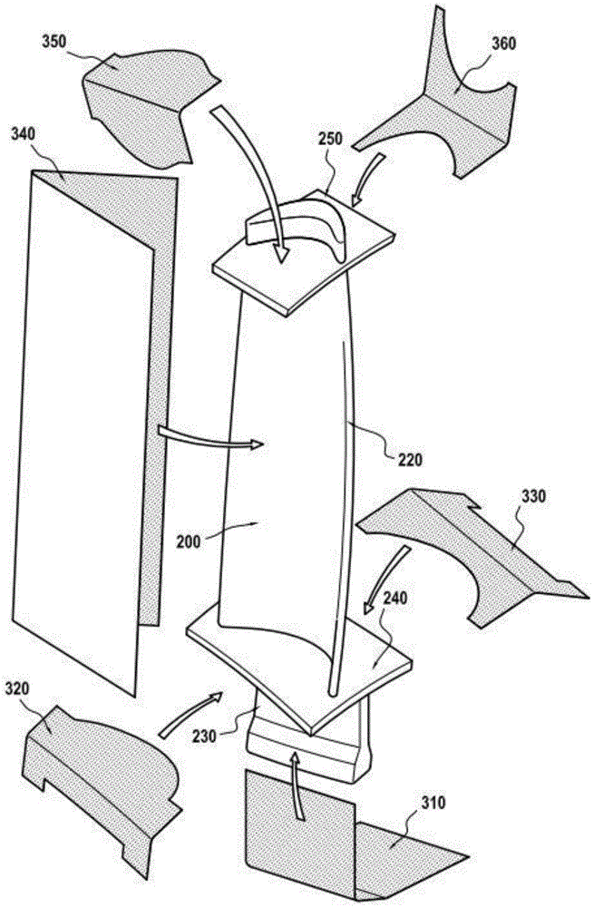
In the embodiment described herein and as shown in fig. 7, several layers 310, 320, 330, 340, 350 and 360 are cut, the layer 310 being intended to overlie the portion 230 of the root preform of the preform core. Layers 320 and 330 are intended to overlie platform preform portion 240. Layer 340 is intended to overlie airfoil preform portion 220. The layers 350 and 360 are intended to overlie the tang preform portion 250. Depending on the desired thickness, several layers 310, 320, 330, 340, 350, and 360 may be overlaid on the respective preform core portions.
The production of the blade continues by covering the pre-form core with one or more unidirectional pre-preg layers obtained as described above (step 760 in fig. 7).
Once the preform core 200 has been covered by the layers 310, 320, 330, 340, 350 and 360, the assembly thus formed is placed in a baking mold (step 280) for heat treatment in step 280. The heat treatment performed in step 280 corresponds to polymerization and pyrolysis. A hybrid fiber preform consisting of 3D woven preform core 200 and layers 310, 320, 330, 340, 350, and 360 bonded thereto is then obtained.
In step 290, the hybrid fiber preform is densified by infiltrating it with a silicon melt composition, corresponding to the well-known Melt Infiltration (MI) method. Carbon residue present in the hybrid preform (in particularProduced by pyrolysis) reacts with silicon to form SiC. SiC or Si pre-introduced into the core of the preform3N4The particles are bonded together by silicon to form a matrix made mainly of ceramic.
As shown in FIG. 8, a ceramic matrix composite or CMC blade 10 is thereby obtained having a porosity of less than 10% while having an exterior surface exhibiting a fully or partially smooth surface finish. The blade 10 includes an airfoil 20, a root 30 formed from a portion of greater thickness, for example having a bulbous or dovetail cross-section extending from a strut 32, an inner platform 40 located between the strut 32 and the airfoil 20, and an outer platform or tang 50 located near the free end of the airfoil.
The outer surface of the blade may be coated with a ceramic "paint" layer or Environmental Barrier Coating (EBC) having thermal and/or corrosion protection in an oxidizing and/or humid environment.