CN112582811A - Mineral insulated flexible fireproof cable and processing method thereof - Google Patents

Mineral insulated flexible fireproof cable and processing method thereof Download PDF

Info

Publication number
CN112582811A
CN112582811A CN202011178450.1A CN202011178450A CN112582811A CN 112582811 A CN112582811 A CN 112582811A CN 202011178450 A CN202011178450 A CN 202011178450A CN 112582811 A CN112582811 A CN 112582811A
Authority
CN
China
Prior art keywords
wall
limiting
sleeve
cable
semicircular ring
Prior art date
Legal status (The legal status is an assumption and is not a legal conclusion. Google has not performed a legal analysis and makes no representation as to the accuracy of the status listed.)
Pending
Application number
CN202011178450.1A
Other languages
Chinese (zh)
Inventor
王荣才
王新飞
Current Assignee (The listed assignees may be inaccurate. Google has not performed a legal analysis and makes no representation or warranty as to the accuracy of the list.)
Jiangsu Sanqi Cable And Wire Co ltd
Original Assignee
Jiangsu Sanqi Cable And Wire Co ltd
Priority date (The priority date is an assumption and is not a legal conclusion. Google has not performed a legal analysis and makes no representation as to the accuracy of the date listed.)
Filing date
Publication date
Application filed by Jiangsu Sanqi Cable And Wire Co ltd filed Critical Jiangsu Sanqi Cable And Wire Co ltd
Priority to CN202011178450.1A priority Critical patent/CN112582811A/en
Publication of CN112582811A publication Critical patent/CN112582811A/en
Pending legal-status Critical Current

Links

Images

Classifications

    • HELECTRICITY
    • H01ELECTRIC ELEMENTS
    • H01RELECTRICALLY-CONDUCTIVE CONNECTIONS; STRUCTURAL ASSOCIATIONS OF A PLURALITY OF MUTUALLY-INSULATED ELECTRICAL CONNECTING ELEMENTS; COUPLING DEVICES; CURRENT COLLECTORS
    • H01R4/00Electrically-conductive connections between two or more conductive members in direct contact, i.e. touching one another; Means for effecting or maintaining such contact; Electrically-conductive connections having two or more spaced connecting locations for conductors and using contact members penetrating insulation
    • H01R4/70Insulation of connections
    • HELECTRICITY
    • H01ELECTRIC ELEMENTS
    • H01BCABLES; CONDUCTORS; INSULATORS; SELECTION OF MATERIALS FOR THEIR CONDUCTIVE, INSULATING OR DIELECTRIC PROPERTIES
    • H01B13/00Apparatus or processes specially adapted for manufacturing conductors or cables
    • H01B13/02Stranding-up
    • HELECTRICITY
    • H01ELECTRIC ELEMENTS
    • H01BCABLES; CONDUCTORS; INSULATORS; SELECTION OF MATERIALS FOR THEIR CONDUCTIVE, INSULATING OR DIELECTRIC PROPERTIES
    • H01B13/00Apparatus or processes specially adapted for manufacturing conductors or cables
    • H01B13/06Insulating conductors or cables
    • H01B13/065Insulating conductors with lacquers or enamels
    • HELECTRICITY
    • H01ELECTRIC ELEMENTS
    • H01BCABLES; CONDUCTORS; INSULATORS; SELECTION OF MATERIALS FOR THEIR CONDUCTIVE, INSULATING OR DIELECTRIC PROPERTIES
    • H01B13/00Apparatus or processes specially adapted for manufacturing conductors or cables
    • H01B13/22Sheathing; Armouring; Screening; Applying other protective layers
    • H01B13/26Sheathing; Armouring; Screening; Applying other protective layers by winding, braiding or longitudinal lapping
    • HELECTRICITY
    • H01ELECTRIC ELEMENTS
    • H01BCABLES; CONDUCTORS; INSULATORS; SELECTION OF MATERIALS FOR THEIR CONDUCTIVE, INSULATING OR DIELECTRIC PROPERTIES
    • H01B3/00Insulators or insulating bodies characterised by the insulating materials; Selection of materials for their insulating or dielectric properties
    • H01B3/02Insulators or insulating bodies characterised by the insulating materials; Selection of materials for their insulating or dielectric properties mainly consisting of inorganic substances
    • H01B3/025Other inorganic material
    • HELECTRICITY
    • H01ELECTRIC ELEMENTS
    • H01BCABLES; CONDUCTORS; INSULATORS; SELECTION OF MATERIALS FOR THEIR CONDUCTIVE, INSULATING OR DIELECTRIC PROPERTIES
    • H01B3/00Insulators or insulating bodies characterised by the insulating materials; Selection of materials for their insulating or dielectric properties
    • H01B3/02Insulators or insulating bodies characterised by the insulating materials; Selection of materials for their insulating or dielectric properties mainly consisting of inorganic substances
    • H01B3/06Insulators or insulating bodies characterised by the insulating materials; Selection of materials for their insulating or dielectric properties mainly consisting of inorganic substances asbestos
    • HELECTRICITY
    • H01ELECTRIC ELEMENTS
    • H01BCABLES; CONDUCTORS; INSULATORS; SELECTION OF MATERIALS FOR THEIR CONDUCTIVE, INSULATING OR DIELECTRIC PROPERTIES
    • H01B3/00Insulators or insulating bodies characterised by the insulating materials; Selection of materials for their insulating or dielectric properties
    • H01B3/18Insulators or insulating bodies characterised by the insulating materials; Selection of materials for their insulating or dielectric properties mainly consisting of organic substances
    • H01B3/28Insulators or insulating bodies characterised by the insulating materials; Selection of materials for their insulating or dielectric properties mainly consisting of organic substances natural or synthetic rubbers
    • HELECTRICITY
    • H01ELECTRIC ELEMENTS
    • H01BCABLES; CONDUCTORS; INSULATORS; SELECTION OF MATERIALS FOR THEIR CONDUCTIVE, INSULATING OR DIELECTRIC PROPERTIES
    • H01B7/00Insulated conductors or cables characterised by their form
    • H01B7/02Disposition of insulation
    • H01B7/0208Cables with several layers of insulating material
    • H01B7/0225Three or more layers
    • HELECTRICITY
    • H01ELECTRIC ELEMENTS
    • H01BCABLES; CONDUCTORS; INSULATORS; SELECTION OF MATERIALS FOR THEIR CONDUCTIVE, INSULATING OR DIELECTRIC PROPERTIES
    • H01B7/00Insulated conductors or cables characterised by their form
    • H01B7/17Protection against damage caused by external factors, e.g. sheaths or armouring
    • H01B7/18Protection against damage caused by wear, mechanical force or pressure; Sheaths; Armouring
    • H01B7/1875Multi-layer sheaths
    • HELECTRICITY
    • H01ELECTRIC ELEMENTS
    • H01BCABLES; CONDUCTORS; INSULATORS; SELECTION OF MATERIALS FOR THEIR CONDUCTIVE, INSULATING OR DIELECTRIC PROPERTIES
    • H01B7/00Insulated conductors or cables characterised by their form
    • H01B7/17Protection against damage caused by external factors, e.g. sheaths or armouring
    • H01B7/18Protection against damage caused by wear, mechanical force or pressure; Sheaths; Armouring
    • H01B7/22Metal wires or tapes, e.g. made of steel
    • HELECTRICITY
    • H01ELECTRIC ELEMENTS
    • H01BCABLES; CONDUCTORS; INSULATORS; SELECTION OF MATERIALS FOR THEIR CONDUCTIVE, INSULATING OR DIELECTRIC PROPERTIES
    • H01B7/00Insulated conductors or cables characterised by their form
    • H01B7/17Protection against damage caused by external factors, e.g. sheaths or armouring
    • H01B7/28Protection against damage caused by moisture, corrosion, chemical attack or weather
    • H01B7/282Preventing penetration of fluid, e.g. water or humidity, into conductor or cable
    • HELECTRICITY
    • H01ELECTRIC ELEMENTS
    • H01BCABLES; CONDUCTORS; INSULATORS; SELECTION OF MATERIALS FOR THEIR CONDUCTIVE, INSULATING OR DIELECTRIC PROPERTIES
    • H01B7/00Insulated conductors or cables characterised by their form
    • H01B7/17Protection against damage caused by external factors, e.g. sheaths or armouring
    • H01B7/29Protection against damage caused by extremes of temperature or by flame
    • HELECTRICITY
    • H02GENERATION; CONVERSION OR DISTRIBUTION OF ELECTRIC POWER
    • H02GINSTALLATION OF ELECTRIC CABLES OR LINES, OR OF COMBINED OPTICAL AND ELECTRIC CABLES OR LINES
    • H02G1/00Methods or apparatus specially adapted for installing, maintaining, repairing or dismantling electric cables or lines
    • H02G1/14Methods or apparatus specially adapted for installing, maintaining, repairing or dismantling electric cables or lines for joining or terminating cables

Landscapes

  • Engineering & Computer Science (AREA)
  • Manufacturing & Machinery (AREA)
  • Chemical & Material Sciences (AREA)
  • Inorganic Chemistry (AREA)
  • Physics & Mathematics (AREA)
  • Spectroscopy & Molecular Physics (AREA)
  • Cable Accessories (AREA)

Abstract

本发明公开了一种矿物绝缘柔性防火电缆及其加工方法,包括绝缘连接块、第一限位套筒、连接端母、绝缘套、矿物绝缘层、钢丝网、石棉层、绝缘橡胶层、防护套筒、储水槽、第二限位套筒、第一半圆环、第一限位块、通孔、第二半圆环、第二限位块、转动轴、第三限位块、第四限位块和螺钉;该发明安全、可靠,通过绝缘连接块、第一限位套筒和连接端母的配合,结构简单,使用方便,实现了稳定连接矿物绝缘电缆的目的;通过储水槽、第二限位套筒、第一半圆环、第一限位块、第二半圆环、转动轴、第三限位块、第四限位块、第二螺纹孔和螺钉的配合,在不影响该矿物绝缘电缆柔韧性的同时,提高了该矿物绝缘电缆的防水功能。

Figure 202011178450

The invention discloses a mineral insulated flexible fireproof cable and a processing method thereof. Sleeve, Water Storage Tank, Second Limit Sleeve, First Half Ring, First Limit Block, Through Hole, Second Half Ring, Second Limit Block, Rotating Shaft, Third Limit Block, No. Four limit blocks and screws; the invention is safe and reliable, through the cooperation of the insulating connecting block, the first limit sleeve and the connecting end nut, the structure is simple, the use is convenient, and the purpose of stably connecting the mineral insulated cables is achieved; through the water storage tank , the cooperation of the second limit sleeve, the first half ring, the first limit block, the second half ring, the rotating shaft, the third limit block, the fourth limit block, the second threaded hole and the screw, The waterproof function of the mineral insulated cable is improved without affecting the flexibility of the mineral insulated cable.

Figure 202011178450

Description

Mineral insulated flexible fireproof cable and processing method thereof
Technical Field
The invention relates to the technical field of cable processing equipment, in particular to a mineral insulation flexible fireproof cable and a processing method thereof.
Background
Due to the wide use of cable equipment, certain requirements are made on some mineral insulated cables in the market at the present stage; however, when the existing mineral insulated cable is used for connection, the connection structure is simpler, the connection stability is influenced, and the use is inconvenient; and the fireproof performance of the existing mineral insulated cable is not enough, and the service life is influenced, so that the invention of the mineral insulated flexible fireproof cable and the processing method thereof at the present stage is very necessary.
Disclosure of Invention
The invention aims to provide a mineral insulated flexible fireproof cable and a processing method thereof, so as to solve the problems in the background technology.
In order to solve the technical problems, the invention provides the following technical scheme: a mineral insulation flexible fireproof cable comprises an insulation connecting block, a first limiting groove, a second limiting groove, a first limiting sleeve, an anti-skid tooth, a connecting terminal female, a copper wire, an insulation paint layer, an insulation sleeve, a mineral insulation layer, a steel wire mesh, an asbestos layer, an insulation rubber layer, a protective sleeve, a water storage tank, a second limiting sleeve, a first semicircular ring, a first limiting block, a through hole, a second semicircular ring, a second limiting block, a rotating shaft, a first limiting semicircular ring, a second limiting semicircular ring, a third limiting block, a first threaded hole, a fourth limiting block, a second threaded hole, a screw and an external thread, wherein the outer walls of two sides of the insulation connecting block are symmetrically provided with the first limiting groove, the inner wall of one side of the first limiting groove is rotatably connected with the first limiting sleeve, the inner wall of one side of the insulation connecting block is provided with the second limiting groove in a distributed and penetrating manner, the inner wall of one side of the second limiting groove is fixedly, a copper wire is inserted into the inner wall of one side of the connecting terminal female, an insulating paint layer is arranged on the outer wall of one side of the copper wire, an insulating sleeve is sleeved on the outer wall of one side of the copper wire, a mineral insulating layer is arranged on the outer wall of one side of the copper wire, an asbestos layer is sleeved on the outer wall of one side of the mineral insulating layer, an insulating rubber layer is sleeved on the outer wall of one side of the steel wire mesh, a first limiting sleeve is sleeved on the outer wall of one side of the insulating rubber layer, a protecting sleeve barrel is sleeved on the outer wall of one side of the insulating rubber layer, a water storage tank is arranged on the inner wall of one side of the protecting sleeve, second limiting sleeves are fixedly connected to the outer walls of two sides of the protecting sleeve, a first semicircular ring is sleeved on the outer wall of one side of the second limiting sleeve, a first limiting block is fixedly connected to the outer wall of one side of, one side of first semicircle ring is rotated and is connected with the second semicircle ring, fixedly connected with second stopper on one side outer wall of second semicircle ring, fixedly connected with axis of rotation on the both sides outer wall of second stopper, and the axis of rotation rotates and connects on one side inner wall of through-hole, fixedly connected with third stopper on one side outer wall of first semicircle ring, link up on one side outer wall of third stopper and seted up first screw hole, threaded connection has the screw on one side inner wall of first screw hole, fixedly connected with fourth stopper on one side outer wall of second semicircle ring, link up on one side outer wall of fourth stopper and seted up the second screw hole, and the one end threaded connection of screw is in the inside of second screw hole.
A processing method of a mineral insulated flexible fireproof cable comprises the steps of processing a copper conductor; secondly, twisting the cable; step three, processing the insulating material; step four, processing the protective material;
in the first step, the copper wire processing comprises the following steps;
1) processing a cable copper conductor with a proper size by using copper conductor processing equipment;
2) plating an insulating paint layer outside the copper conductor of the cable;
in the second step, a plurality of cable copper conductors are stranded into a single-stranded cable conductor by a cable stranding machine;
in the third step, the processing of the insulating material comprises the following steps;
1) processing an insulating sleeve outside the copper conductor of the cable;
2) winding a plurality of cable conductors together, and processing a mineral insulating layer outside the plurality of cable conductors;
3) then sleeving an asbestos layer on the mineral insulating layer;
in the fourth step, the processing of the protective material comprises the following steps;
1) sleeving a layer of steel wire mesh outside the asbestos layer;
2) and an insulating rubber layer is sleeved on the outer side of the steel wire mesh.
According to the technical scheme, the outer wall of one side of the first limiting sleeve is provided with the outer thread, and the first limiting sleeve is connected with the insulating connecting block through the outer thread.
According to the technical scheme, the outer wall of one side of the first limiting sleeve is provided with the anti-skidding teeth.
According to the technical scheme, the two ends of the connecting terminal nut are provided with the conical holes, and the copper conducting wires are inserted in the conical holes.
According to the technical scheme, the outer wall of one side of the asbestos layer is sleeved with the steel wire mesh.
According to the technical scheme, the inner wall of one side of the first semicircular ring is fixedly connected with a first limiting semicircular ring, and the inner wall of one side of the second semicircular ring is fixedly connected with a second limiting semicircular ring.
Compared with the prior art, the invention has the following beneficial effects: the mineral insulated cable connecting device is safe and reliable, simple in structure and convenient to use through the matching of the insulated connecting block, the first limiting sleeve and the connecting terminal nut, and achieves the purpose of stably connecting the mineral insulated cable; through the matching of the insulating sleeve, the mineral insulating layer, the steel wire mesh, the asbestos layer, the insulating rubber layer and the protective sleeve, the mineral insulating cable has strong fire resistance and flexibility; through the cooperation of aqua storage tank, second stop sleeve, first semicircle ring, first stopper, second semicircle ring, axis of rotation, third stopper, fourth stopper, second screw hole and screw, when not influencing this mineral insulated cable pliability, improved this mineral insulated cable's waterproof function.
Drawings
The accompanying drawings, which are included to provide a further understanding of the invention and are incorporated in and constitute a part of this specification, illustrate embodiments of the invention and together with the description serve to explain the principles of the invention and not to limit the invention. In the drawings:
fig. 1 is an overall front view structure diagram of the present invention.
Fig. 2 is a front sectional structure schematic view of the insulation connection block of the invention.
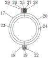
Fig. 3 is a side sectional view of the first semicircular ring of the present invention.
Fig. 4 is a front sectional structural schematic view of a second limiting sleeve of the present invention.
Fig. 5 is a schematic perspective view of a second stop collar of the present invention.
Fig. 6 is a schematic perspective view of the mineral insulated cable of the present invention.
Fig. 7 is a flow chart of a method of the present invention.
In the figure: 1. an insulating connecting block; 2. a first limit groove; 3. a second limit groove; 4. a first limit sleeve; 5. anti-slip teeth; 6. connecting a terminal nut; 7. a copper wire; 8. an insulating paint layer; 9. an insulating sleeve; 10. a mineral insulation layer; 11. steel wire mesh; 12. an asbestos layer; 13. an insulating rubber layer; 14. a protective sleeve; 15. a water storage tank; 16. a second limit sleeve; 17. a first semicircular ring; 18. a first stopper; 19. a through hole; 20. a second semi-circular ring; 21. a second limiting block; 22. a rotating shaft; 23. a first limit semicircular ring; 24. a second limit semicircular ring; 25. a third limiting block; 26. a first threaded hole; 27. a fourth limiting block; 28. a second threaded hole; 29. a screw; 30. and (4) external threads.
Detailed Description
The technical solutions in the embodiments of the present invention will be clearly and completely described below with reference to the drawings in the embodiments of the present invention, and it is obvious that the described embodiments are only a part of the embodiments of the present invention, and not all of the embodiments. All other embodiments, which can be derived by a person skilled in the art from the embodiments given herein without making any creative effort, shall fall within the protection scope of the present invention.
Referring to fig. 1-6, the present invention provides a technical solution: a mineral insulation flexible fireproof cable comprises an insulation connecting block 1, a first limiting groove 2, a second limiting groove 3, a first limiting sleeve 4, an anti-skid tooth 5, a connecting terminal nut 6, a copper wire 7, an insulation paint layer 8, an insulation sleeve 9, a mineral insulation layer 10, a steel wire mesh 11, an asbestos layer 12, an insulation rubber layer 13, a protective sleeve 14, a water storage tank 15, a second limiting sleeve 16, a first semicircular ring 17, a first limiting block 18, a through hole 19, a second semicircular ring 20, a second limiting block 21, a rotating shaft 22, a first limiting semicircular ring 23, a second limiting semicircular ring 24, a third limiting block 25, a first threaded hole 26, a fourth limiting block 27, a second threaded hole 28, a screw 29 and an external thread 30, wherein the first limiting groove 2 is symmetrically formed on the outer walls of two sides of the insulation connecting block 1, the first limiting sleeve 4 is rotatably connected to the inner wall of one side of the first limiting groove 2, the external thread 30 is formed on the outer wall of one side of the first limiting sleeve 4, the first limiting sleeve 4 is connected with the insulating connecting block 1 through an external thread 30, the outer wall of one side of the first limiting sleeve 4 is provided with an anti-skid tooth 5, the inner wall of one side of the insulating connecting block 1 is provided with a second limiting groove 3 in a distributed and penetrating way, the inner wall of one side of the second limiting groove 3 is fixedly connected with a connecting terminal 6, the inner wall of one side of the connecting terminal 6 is spliced with a copper wire 7, the outer wall of one side of the copper wire 7 is provided with an insulating paint layer 8, the outer wall of one side of the copper wire 7 is sleeved with an insulating sleeve 9, the outer wall of one side of the copper wire 7 is provided with a mineral insulating layer 10, the outer wall of one side of the mineral insulating layer 10 is sleeved with an asbestos layer 12, the outer wall of one side of the asbestos layer 12 is sleeved with a steel wire mesh 11, the outer wall of one side of the steel wire mesh 11 is sleeved with an insulating rubber layer 13, the first limiting, a water storage groove 15 is arranged on the inner wall of one side of the protective sleeve 14, a second limiting sleeve 16 is fixedly connected on the outer wall of two sides of the protective sleeve 14, a first semicircular ring 17 is sleeved on the outer wall of one side of the second limiting sleeve 16, a first limiting block 18 is fixedly connected on the outer wall of one side of the first semicircular ring 17, a through hole 19 is arranged on the outer wall of one side of the first limiting block 18 in a penetrating way, a second semicircular ring 20 is rotatably connected on one side of the first semicircular ring 17, a first limiting semicircular ring 23 is fixedly connected on the inner wall of one side of the first semicircular ring 17, a second limiting semicircular ring 24 is fixedly connected on the inner wall of one side of the second semicircular ring 20, a second limiting block 21 is fixedly connected on the outer wall of one side of the second semicircular ring 20, a rotating shaft 22 is fixedly connected on the outer wall of two sides of the second limiting block 21, and the rotating shaft 22 is rotatably connected on the inner wall of one side of the, a first threaded hole 26 is formed in the outer wall of one side of the third limiting block 25 in a penetrating manner, a screw 29 is connected to the inner wall of one side of the first threaded hole 26 in a threaded manner, a fourth limiting block 27 is fixedly connected to the outer wall of one side of the second semicircular ring 20 in a penetrating manner, a second threaded hole 28 is formed in the outer wall of one side of the fourth limiting block 27 in a penetrating manner, and one end of the screw 29 is connected to the inside of the second threaded hole 28 in a threaded manner.
Referring to fig. 7, the present invention provides a technical solution: a processing method of a mineral insulated flexible fireproof cable comprises the steps of processing a copper conductor; secondly, twisting the cable; step three, processing the insulating material; step four, processing the protective material;
in the first step, the copper wire processing comprises the following steps;
1) processing a cable copper conductor 7 with a proper size by copper conductor processing equipment;
2) electrically plating an insulating paint layer 8 outside the copper conductor 7 of the cable;
in the second step, a plurality of cable copper conductors 7 are stranded into a single-stranded cable conductor by a cable stranding machine;
in the third step, the processing of the insulating material comprises the following steps;
1) processing an insulating sleeve 9 outside the cable copper conductor 7;
2) winding a plurality of cable conductors together, and processing a mineral insulating layer (10) outside the plurality of cable conductors;
3) then the mineral insulating layer 10 is sleeved with an asbestos layer 12;
in the fourth step, the processing of the protective material comprises the following steps;
1) a steel wire mesh 11 is sleeved outside the asbestos layer 12;
2) and an insulating rubber layer 13 is sleeved outside the steel wire mesh 11.
Based on the above, the invention has the advantages that when the invention is used, the second limiting sleeve 16 storing cooling water is sleeved on the mineral insulated cable, the second limiting sleeve 16 is distributed and limited on the mineral insulated cable through the matching of the first semicircular ring 17, the second semicircular ring 20 and the screw 29, the copper conductor 7 at one end of the mineral insulated cable is inserted into the connecting terminal mother 6 after the insulating paint layer 8 is removed, the second limiting sleeve 16 is rotated, the two mineral insulated cables are connected through the matching of the external thread 30, glue is coated on the outer sides of the second limiting sleeve 16 and the insulating rubber layer 13, the connection is stable, and the connection of the cables is completed.
It is noted that, herein, relational terms such as first and second, and the like may be used solely to distinguish one entity or action from another entity or action without necessarily requiring or implying any actual such relationship or order between such entities or actions. Also, the terms "comprises," "comprising," or any other variation thereof, are intended to cover a non-exclusive inclusion, such that a process, method, article, or apparatus that comprises a list of elements does not include only those elements but may include other elements not expressly listed or inherent to such process, method, article, or apparatus.
Finally, it should be noted that: although the present invention has been described in detail with reference to the foregoing embodiments, it will be apparent to those skilled in the art that changes may be made in the embodiments and/or equivalents thereof without departing from the spirit and scope of the invention. Any modification, equivalent replacement, or improvement made within the spirit and principle of the present invention should be included in the protection scope of the present invention.

Claims (7)

1. A mineral insulation flexible fireproof cable comprises an insulation connecting block (1), a first limiting groove (2), a second limiting groove (3), a first limiting sleeve (4), an anti-skidding tooth (5), a connecting terminal nut (6), a copper wire (7), an insulation paint layer (8), an insulation sleeve (9), a mineral insulation layer (10), a steel wire mesh (11), an asbestos layer (12), an insulation rubber layer (13), a protective sleeve (14), a water storage tank (15), a second limiting sleeve (16), a first semicircular ring (17), a first limiting block (18), a through hole (19), a second semicircular ring (20), a second limiting block (21), a rotating shaft (22), a first limiting semicircular ring (23), a second limiting semicircular ring (24), a third limiting block (25), a first threaded hole (26), a fourth limiting block (27), a second threaded hole (28), a screw (29) and external threads (30), the method is characterized in that: the insulation connection block is characterized in that first limiting grooves (2) are symmetrically formed in the outer walls of two sides of the insulation connection block (1), a first limiting sleeve (4) is connected to the inner wall of one side of the first limiting groove (2) in a rotating mode, second limiting grooves (3) are distributed and communicated on the inner wall of one side of the insulation connection block (1), a connecting terminal female (6) is fixedly connected to the inner wall of one side of the second limiting groove (3), a copper wire (7) is inserted into the inner wall of one side of the connecting terminal female (6), an insulation paint layer (8) is arranged on the outer wall of one side of the copper wire (7), an insulation sleeve (9) is sleeved on the outer wall of one side of the copper wire (7), a mineral insulation layer (10) is arranged on the outer wall of one side of the mineral insulation layer (10), an insulation rubber layer (13) is sleeved on the outer wall of one side of the steel wire mesh (11), the first limiting sleeve (4) is sleeved on the outer wall of one side of the insulating rubber layer (13), the protecting sleeve (14) is sleeved on the outer wall of one side of the insulating rubber layer (13), the water storage tank (15) is arranged on the inner wall of one side of the protecting sleeve (14), the outer walls of two sides of the protecting sleeve (14) are fixedly connected with second limiting sleeves (16), the outer wall of one side of each second limiting sleeve (16) is sleeved with a first semicircular ring (17), the outer wall of one side of each first semicircular ring (17) is fixedly connected with a first limiting block (18), the outer wall of one side of each first limiting block (18) is provided with a through hole (19) in a penetrating manner, one side of each first semicircular ring (17) is rotatably connected with a second semicircular ring (20), the outer wall of one side of each second semicircular ring (20) is fixedly connected with a second limiting block (21), and the outer walls of two sides of each second limiting block (21) are fixedly connected with rotating shafts, and axis of rotation (22) rotate to be connected on one side inner wall of through-hole (19), fixedly connected with third stopper (25) on one side outer wall of first semicircle ring (17), link up on one side outer wall of third stopper (25) and seted up first screw hole (26), threaded connection has screw (29) on one side inner wall of first screw hole (26), fixedly connected with fourth stopper (27) on one side outer wall of second semicircle ring (20), link up on one side outer wall of fourth stopper (27) and seted up second screw hole (28), and the one end threaded connection of screw (29) is in the inside of second screw hole (28).
2. A processing method of a mineral insulated flexible fireproof cable comprises the steps of processing a copper conductor; secondly, twisting the cable; step three, processing the insulating material; step four, processing the protective material; the method is characterized in that:
in the first step, the copper wire processing comprises the following steps;
1) processing a cable copper conductor (7) with a proper size by copper conductor processing equipment;
2) electrically plating an insulating paint layer (8) outside the copper conductor (7) of the cable;
in the second step, a plurality of cable copper conductors (7) are stranded into a single-stranded cable conductor by a cable stranding machine;
in the third step, the processing of the insulating material comprises the following steps;
1) processing an insulating sleeve (9) outside the cable copper conductor (7);
2) winding a plurality of cable conductors together, and processing a mineral insulating layer (10) outside the plurality of cable conductors;
3) then an asbestos layer (12) is sleeved on the mineral insulating layer (10);
in the fourth step, the processing of the protective material comprises the following steps;
1) a steel wire mesh (11) is sleeved outside the asbestos layer (12);
2) and an insulating rubber layer (13) is sleeved on the outer side of the steel wire mesh (11).
3. A mineral insulated flexible fire-protected cable according to claim 1, wherein: an external thread (30) is formed in the outer wall of one side of the first limiting sleeve (4), and the first limiting sleeve (4) is connected with the insulating connecting block (1) through the external thread (30).
4. A mineral insulated flexible fire-protected cable according to claim 1, wherein: and the outer wall of one side of the first limiting sleeve (4) is provided with anti-skidding teeth (5).
5. A mineral insulated flexible fire-protected cable according to claim 1, wherein: the two ends of the connecting terminal (6) are provided with conical holes, and the copper conducting wire (7) is inserted in the conical holes.
6. A mineral insulated flexible fire-protected cable according to claim 1, wherein: and a steel wire mesh (11) is sleeved on the outer wall of one side of the asbestos layer (12).
7. A mineral insulated flexible fire-protected cable according to claim 1, wherein: the inner wall of one side of the first semicircular ring (17) is fixedly connected with a first limiting semicircular ring (23), and the inner wall of one side of the second semicircular ring (20) is fixedly connected with a second limiting semicircular ring (24).
CN202011178450.1A 2020-10-29 2020-10-29 Mineral insulated flexible fireproof cable and processing method thereof Pending CN112582811A (en)

Priority Applications (1)

Application Number Priority Date Filing Date Title
CN202011178450.1A CN112582811A (en) 2020-10-29 2020-10-29 Mineral insulated flexible fireproof cable and processing method thereof

Applications Claiming Priority (1)

Application Number Priority Date Filing Date Title
CN202011178450.1A CN112582811A (en) 2020-10-29 2020-10-29 Mineral insulated flexible fireproof cable and processing method thereof

Publications (1)

Publication Number Publication Date
CN112582811A true CN112582811A (en) 2021-03-30

Family

ID=75119856

Family Applications (1)

Application Number Title Priority Date Filing Date
CN202011178450.1A Pending CN112582811A (en) 2020-10-29 2020-10-29 Mineral insulated flexible fireproof cable and processing method thereof

Country Status (1)

Country Link
CN (1) CN112582811A (en)

Citations (8)

* Cited by examiner, † Cited by third party
Publication number Priority date Publication date Assignee Title
US3544700A (en) * 1966-12-30 1970-12-01 Pirelli Electrical cable joints
US20080087466A1 (en) * 2006-10-17 2008-04-17 Emerson Tod D Splice for down hole electrical submersible pump cable
US20150207245A1 (en) * 2012-06-27 2015-07-23 Quick Connectors, Inc. Power Cable Splice Sleeve and Method of Installation
CN105913950A (en) * 2016-07-06 2016-08-31 芜湖航天特种电缆厂股份有限公司 Asbestos-based high-temperature resistant cable and manufacturing method thereof
CN208707049U (en) * 2018-09-18 2019-04-05 惠州市太金电线电缆有限公司 A kind of wear-resisting USB data line
CN209266600U (en) * 2019-03-16 2019-08-16 王蒙 A kind of cable connector
CN111653395A (en) * 2019-11-07 2020-09-11 人民电器集团上海有限公司 A smart cable resistant to high temperature and salt and alkali
CN213520363U (en) * 2020-10-29 2021-06-22 江苏三旗线缆有限公司 A mineral insulated flexible fireproof cable

Patent Citations (8)

* Cited by examiner, † Cited by third party
Publication number Priority date Publication date Assignee Title
US3544700A (en) * 1966-12-30 1970-12-01 Pirelli Electrical cable joints
US20080087466A1 (en) * 2006-10-17 2008-04-17 Emerson Tod D Splice for down hole electrical submersible pump cable
US20150207245A1 (en) * 2012-06-27 2015-07-23 Quick Connectors, Inc. Power Cable Splice Sleeve and Method of Installation
CN105913950A (en) * 2016-07-06 2016-08-31 芜湖航天特种电缆厂股份有限公司 Asbestos-based high-temperature resistant cable and manufacturing method thereof
CN208707049U (en) * 2018-09-18 2019-04-05 惠州市太金电线电缆有限公司 A kind of wear-resisting USB data line
CN209266600U (en) * 2019-03-16 2019-08-16 王蒙 A kind of cable connector
CN111653395A (en) * 2019-11-07 2020-09-11 人民电器集团上海有限公司 A smart cable resistant to high temperature and salt and alkali
CN213520363U (en) * 2020-10-29 2021-06-22 江苏三旗线缆有限公司 A mineral insulated flexible fireproof cable

Similar Documents

Publication Publication Date Title
CN105185482A (en) Manufacturing method of cable having waterproof outer sheath structure
CN213520363U (en) A mineral insulated flexible fireproof cable
CN208522091U (en) Photovoltaic conflux private cable with fast joint
CN112582811A (en) Mineral insulated flexible fireproof cable and processing method thereof
CN209786284U (en) Blind-insertion quick push-pull self-locking connector
CN103779019A (en) Power cables for ships and offshore oil platforms
CN207116092U (en) The wind-power tower power cable of band connection terminal
CN206236438U (en) A kind of pliability is good and cable of connection easy to install
CN205081445U (en) Brand -new graphite alkene stress cone for cable accessories
CN212323227U (en) Cable connector lug
CN214124152U (en) Cable joint with tight connection
CN210777896U (en) A high air tightness pre-branch cable
CN204496966U (en) 6.6kV naval vessel midium voltage cable
CN207867922U (en) USB cable
CN103236606B (en) Fracture connecting device for monomer wire circuit
CN211045937U (en) Humidity-heat-resistant, high-temperature-resistant and light-weight airborne cable
CN203135096U (en) Waterproof and moistureproof external member for cable conductor wiring nude position
CN207474721U (en) A kind of electronic connector outer jointing jacket
CN205122227U (en) High temperature resistant dive motor winding line
CN221899777U (en) A bending-resistant and corrosion-resistant medical cable
CN205542134U (en) Cable
CN205542039U (en) Notebook power charging wire
CN215730991U (en) Electronic wire
CN206075859U (en) A kind of insulation and moisture home improvement wire
CN110534938A (en) Water proof type connecting terminal

Legal Events

Date Code Title Description
PB01 Publication
PB01 Publication
SE01 Entry into force of request for substantive examination
RJ01 Rejection of invention patent application after publication

Application publication date: 20210330

RJ01 Rejection of invention patent application after publication