CN112886111A - Lithium battery sealing structure - Google Patents
Lithium battery sealing structure Download PDFInfo
- Publication number
- CN112886111A CN112886111A CN202110119849.0A CN202110119849A CN112886111A CN 112886111 A CN112886111 A CN 112886111A CN 202110119849 A CN202110119849 A CN 202110119849A CN 112886111 A CN112886111 A CN 112886111A
- Authority
- CN
- China
- Prior art keywords
- hoop
- thickness
- sealing
- lithium battery
- side wall
- Prior art date
- Legal status (The legal status is an assumption and is not a legal conclusion. Google has not performed a legal analysis and makes no representation as to the accuracy of the status listed.)
- Granted
Links
- 238000007789 sealing Methods 0.000 title claims abstract description 118
- WHXSMMKQMYFTQS-UHFFFAOYSA-N Lithium Chemical compound [Li] WHXSMMKQMYFTQS-UHFFFAOYSA-N 0.000 title claims abstract description 43
- 229910052744 lithium Inorganic materials 0.000 title claims abstract description 43
- 239000011324 bead Substances 0.000 claims description 8
- XEEYBQQBJWHFJM-UHFFFAOYSA-N Iron Chemical compound [Fe] XEEYBQQBJWHFJM-UHFFFAOYSA-N 0.000 claims description 6
- 229910052782 aluminium Inorganic materials 0.000 claims description 5
- XAGFODPZIPBFFR-UHFFFAOYSA-N aluminium Chemical compound [Al] XAGFODPZIPBFFR-UHFFFAOYSA-N 0.000 claims description 5
- 229910001220 stainless steel Inorganic materials 0.000 claims description 5
- 239000010935 stainless steel Substances 0.000 claims description 5
- 239000000463 material Substances 0.000 claims description 4
- RYGMFSIKBFXOCR-UHFFFAOYSA-N Copper Chemical compound [Cu] RYGMFSIKBFXOCR-UHFFFAOYSA-N 0.000 claims description 3
- 229910052802 copper Inorganic materials 0.000 claims description 3
- 239000010949 copper Substances 0.000 claims description 3
- 229910052742 iron Inorganic materials 0.000 claims description 3
- 230000000694 effects Effects 0.000 abstract description 2
- 238000002788 crimping Methods 0.000 description 8
- 238000000034 method Methods 0.000 description 8
- 230000001965 increasing effect Effects 0.000 description 6
- 230000008569 process Effects 0.000 description 5
- 238000004880 explosion Methods 0.000 description 4
- 238000004519 manufacturing process Methods 0.000 description 4
- 238000005452 bending Methods 0.000 description 3
- 239000007788 liquid Substances 0.000 description 3
- 239000004033 plastic Substances 0.000 description 3
- 229920000642 polymer Polymers 0.000 description 3
- 238000004804 winding Methods 0.000 description 3
- HBBGRARXTFLTSG-UHFFFAOYSA-N Lithium ion Chemical compound [Li+] HBBGRARXTFLTSG-UHFFFAOYSA-N 0.000 description 2
- 229910001416 lithium ion Inorganic materials 0.000 description 2
- 230000002093 peripheral effect Effects 0.000 description 2
- 239000002985 plastic film Substances 0.000 description 2
- 229920006255 plastic film Polymers 0.000 description 2
- 241000238367 Mya arenaria Species 0.000 description 1
- 230000009471 action Effects 0.000 description 1
- 230000008859 change Effects 0.000 description 1
- 230000007547 defect Effects 0.000 description 1
- 230000004069 differentiation Effects 0.000 description 1
- 210000005069 ears Anatomy 0.000 description 1
- 239000003792 electrolyte Substances 0.000 description 1
- 238000005516 engineering process Methods 0.000 description 1
- 230000002708 enhancing effect Effects 0.000 description 1
- 230000007613 environmental effect Effects 0.000 description 1
- 239000003292 glue Substances 0.000 description 1
- 238000009957 hemming Methods 0.000 description 1
- 229910052751 metal Inorganic materials 0.000 description 1
- 239000002184 metal Substances 0.000 description 1
- 238000012986 modification Methods 0.000 description 1
- 230000004048 modification Effects 0.000 description 1
- 238000006864 oxidative decomposition reaction Methods 0.000 description 1
- 238000004806 packaging method and process Methods 0.000 description 1
- 238000002360 preparation method Methods 0.000 description 1
- 238000012797 qualification Methods 0.000 description 1
- 238000000926 separation method Methods 0.000 description 1
- 238000005507 spraying Methods 0.000 description 1
- 230000008961 swelling Effects 0.000 description 1
Images


Classifications
-
- H—ELECTRICITY
- H01—ELECTRIC ELEMENTS
- H01M—PROCESSES OR MEANS, e.g. BATTERIES, FOR THE DIRECT CONVERSION OF CHEMICAL ENERGY INTO ELECTRICAL ENERGY
- H01M10/00—Secondary cells; Manufacture thereof
- H01M10/05—Accumulators with non-aqueous electrolyte
- H01M10/052—Li-accumulators
-
- Y—GENERAL TAGGING OF NEW TECHNOLOGICAL DEVELOPMENTS; GENERAL TAGGING OF CROSS-SECTIONAL TECHNOLOGIES SPANNING OVER SEVERAL SECTIONS OF THE IPC; TECHNICAL SUBJECTS COVERED BY FORMER USPC CROSS-REFERENCE ART COLLECTIONS [XRACs] AND DIGESTS
- Y02—TECHNOLOGIES OR APPLICATIONS FOR MITIGATION OR ADAPTATION AGAINST CLIMATE CHANGE
- Y02E—REDUCTION OF GREENHOUSE GAS [GHG] EMISSIONS, RELATED TO ENERGY GENERATION, TRANSMISSION OR DISTRIBUTION
- Y02E60/00—Enabling technologies; Technologies with a potential or indirect contribution to GHG emissions mitigation
- Y02E60/10—Energy storage using batteries
Landscapes
- Engineering & Computer Science (AREA)
- Manufacturing & Machinery (AREA)
- Chemical & Material Sciences (AREA)
- Chemical Kinetics & Catalysis (AREA)
- Electrochemistry (AREA)
- General Chemical & Material Sciences (AREA)
- Sealing Battery Cases Or Jackets (AREA)
- Secondary Cells (AREA)
Abstract
The invention discloses a lithium battery sealing structure which comprises a top cover, a bottom cover, a hoop ring and a sealing ring, wherein the thickness of the bottom cover is smaller than that of the top cover and the hoop ring, a first surrounding wall is arranged on the side surface of the top cover, a second surrounding wall and a sealing part located above the second surrounding wall are arranged on the side surface of the bottom cover, the sealing ring is arranged between the inner side of the sealing part of the bottom cover and the first surrounding wall of the top cover, and the hoop ring is enclosed around the periphery of the sealing part of the bottom cover. Therefore, the structure is compact, the sealing effect is not influenced, and meanwhile, the thickness and the weight of the bottom shell are greatly reduced, so that the overall weight of the battery is reduced, and the energy density of the battery is improved.
Description
Technical Field
The invention relates to the technical field of batteries, in particular to a lithium battery sealing structure.
Background
A lithium battery is a type of rechargeable battery that mainly operates by movement of lithium ions between a positive electrode and a negative electrode. The button lithium battery has small volume and is often applied to products such as a computer mainboard, an MP3 watch, a calculator, an electronic dictionary, a Bluetooth headset and the like. According to the material differentiation of lithium cell shell, the lithium cell can be divided into crust battery and laminate polymer battery, crust battery mainly is the box hat battery, including the top cap like general button box hat lithium cell, drain pan and sealing washer, the sealing washer sets up between top cap and drain pan, top cap and drain pan are the box hat of certain thickness and make, shell intensity is big, difficult deformation, the preparation is encapsulated to the accessible automated production technology, according to different specifications, the thickness of box hat battery top cap and drain pan is 0.15 ~ 0.3mm approximately, the weight ratio of box hat battery is 40% heavier than the soft shell battery of the same volume, cause battery energy density to be less relatively. Meanwhile, the hard shell battery has a higher pressure resistance value, a similar explosion effect is generated by higher pressure relief required when internal thermal runaway occurs, the explosion-proof safety coefficient is small, and if the hard shell battery is installed in the Bluetooth headset, once an accident occurs, a human body is threatened greatly.
The soft package battery is made of an aluminum plastic film soft package, a polymer shell is sleeved on the liquid lithium ion battery, the soft package battery is light and easy to deform, and only can bulge and crack under the condition of potential safety hazard, so that the explosion accident like a hard-shell battery cannot occur. Pouch cells, however, suffer from the following disadvantages relative to hard shell cells: 1. the soft package battery is difficult to produce the battery cell by adopting a winding method, the automatic production difficulty is high, and the manufacturing cost is high; 2. the aluminum plastic film of the soft package battery cannot be stretched, the height of the battery is limited, and the ideal height cannot be achieved; 3. the sealing part of the small-sized soft package battery occupies large space and has small volume energy ratio, and the battery requirements of small-sized products such as Bluetooth earphones and the like cannot be met; 4. the pressure resistance is weak, the technical and environmental limitations of domestic packaging plants are limited, the expansion rate is too high, the product use qualification rate is low, and the thickness of the battery pole piece is increased due to expansion in the circulation process; swelling due to oxidative decomposition of the electrolyte; the battery package is not tightly expanded due to moisture, corner damage and other process defects. These reasons also make pouch batteries unusable in small products such as bluetooth headsets.
Disclosure of Invention
One object of the present invention is to provide a lithium battery sealing structure, which overcomes the disadvantages of the prior art, has a compact structure, does not affect the sealing strength, and greatly reduces the thickness and weight of a bottom case, thereby reducing the overall weight of the battery and improving the energy density of the battery.
Another object of the present invention is to provide a sealing structure for a lithium battery, which does not require complicated mechanical manufacturing steps and devices, improves sealing performance by adding a hoop, and simultaneously increases an explosion-proof structure, improves safety of use of the lithium battery, so that an earphone with the lithium battery is lighter and safer.
In order to achieve the above purposes, the technical scheme adopted by the invention is as follows: the utility model provides a lithium battery sealing structure includes top cap, drain pan, hoop and sealing washer, the thickness of drain pan is less than the top cap with the thickness of hoop, the side of top cap is equipped with first leg, the side of drain pan is equipped with the second leg and is located the sealing of second leg top, the sealing washer set up in the sealing of drain pan inboard with between the first leg of top cap, the hoop enclose in the sealing periphery of drain pan.
Preferably, the sealing portion integrally protrudes annularly radially outwardly from the second peripheral wall, and the hoop is provided with a side wall and a bottom wall, and the side wall is integrally connected to the bottom wall in a bent manner upwardly, so that the hoop encloses the outer periphery of the sealing portion.
Preferably, the thickness of the bottom shell is about 0.03mm to 0.15mm, the thickness of the top cover is about 0.1mm to 0.25mm, the thickness of the hoop is about 0.1mm to 0.25mm, and the height of the hoop is about 1.2mm to 4.5 mm.
Preferably, the sealing portion includes a protruding section, an extending section and a top section, the extending section vertically connects the protruding section and the top section, the protruding section radially extends outward from the upper end of the second surrounding wall, and the top section is tilted outward from the extending section to the hoop direction, so that the top section deviates from the sealing ring.
Preferably, the side wall of the hoop is provided with an upper side wall and a lower side wall, the thickness of the upper side wall is smaller than that of the lower side wall, the top section faces the upper side wall of the hoop, and the extending section is arranged between the lower side wall of the hoop and the sealing ring.
Preferably, the hoop is provided with a bead portion and at least one buffer portion, the bead portion and the buffer portion are located at an upper edge of the hoop, the bead portion is bent toward the seal ring and contacts the seal ring, and the buffer portion protrudes outward with respect to the bead portion such that a gap is formed between the buffer portion and the seal ring.
Preferably, the first wall of the top cover is provided with a wave band, the wave band is located on the upper side of the first wall, and the wave band is of a multi-segment bent structure.
Preferably, the top cover further includes a first concave portion and a top plate, the first concave portion is annularly and concavely disposed on the top plate, the bottom cover further includes a second concave portion and a bottom plate, the second concave portion is annularly and concavely disposed on the bottom plate, and the first concave portion and the second concave portion are relatively concave.
Preferably, the thickness of the bottom shell is 0.05mm, the thickness of the top cover is 0.15mm, the thickness of the hoop is 0.1mm to 0.15mm, the height of the hoop is 1.5 mm to 2.5mm, the thickness of the upper side wall is 0.1mm, the thickness of the lower side wall and the thickness of the bottom wall are 0.15mm, the bottom shell, the top cover and the hoop are made of one or more materials selected from stainless steel, iron shell, copper shell or aluminum shell, and the number of the buffer parts is three.
Preferably, the sealing structure is suitable for a lithium battery.
Drawings
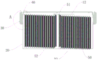
Fig. 1 is a structural perspective view of a lithium battery according to an embodiment of the present application;
fig. 2 is a cross-sectional view (unpackaged state) of a lithium battery according to an embodiment of the present application;
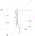
FIG. 3 is an enlarged partial view of the seal structure of FIG. 2A according to the present application;
fig. 4 is a sectional view (packaged state) of a lithium battery according to an embodiment of the present application;
FIG. 5 is an enlarged partial view of the seal configuration of FIG. 4B according to the present application;
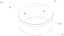
fig. 6 is a perspective view of a bottom chassis according to an embodiment of the present application;
FIG. 7 is a side view of a top cover according to an embodiment of the present application;
FIG. 8 is a perspective view of a hoop according to an embodiment of the present application;
FIG. 9 is a top view of a hoop according to an embodiment of the present application;
FIG. 10 is a cross-sectional view taken along line A-A of FIG. 9 according to the present application.
In the figure: 10. a top cover; 11. a first enclosure wall; 12. a top plate; 13. a wave band; 14. a first concave portion; 20. a bottom case; 21. a second enclosure wall; 22. a base plate; 23. a sealing part; 231. a protruding section; 232. an upper extension section; 233. a top section; 24. a second concave portion; 30. a hoop; 31. a side wall; 311. an upper sidewall; 312. a lower sidewall; 32. a bottom wall; 33. a buffer section; 34. a hemming part; 331. a gap; 40. a seal ring; 50. an electric core; 51. an upper tab; 52. and a lower tab.
Detailed Description
The present invention is further described below with reference to specific embodiments, and it should be noted that, without conflict, any combination between the embodiments or technical features described below may form a new embodiment.
In the description of the present invention, it should be noted that, for the terms of orientation, such as "central", "lateral", "longitudinal", "length", "width", "thickness", "upper", "lower", "front", "rear", "left", "right", "vertical", "horizontal", "top", "bottom", "inner", "outer", etc., it indicates that the orientation and positional relationship are based on those shown in the drawings, and is only for convenience of description and simplification of description, but does not indicate or imply that the device or element referred to must have a specific orientation, be constructed and operated in a specific orientation, and should not be construed as limiting the specific scope of the invention.
It is noted that the terms first, second and the like in the description and in the claims of the present application are used for distinguishing between similar elements and not necessarily for describing a particular sequential or chronological order.
The terms "comprises," "comprising," and "having," and any variations thereof, in the description and claims of this application, are intended to cover a non-exclusive inclusion, such that a process, method, system, article, or apparatus that comprises a list of steps or elements is not necessarily limited to those steps or elements expressly listed, but may include other steps or elements not expressly listed or inherent to such process, method, article, or apparatus.
It is noted that, as used in this application, the terms "substantially," "about," and the like are used as terms of table approximation and not as terms of table degree, and are intended to account for inherent deviations in measured or calculated values that would be recognized by one of ordinary skill in the art.
In the description of the present invention, it should also be noted that, unless otherwise explicitly specified or limited, the terms "disposed," "mounted," "connected," and "connected" are to be construed broadly and may, for example, be fixedly connected, detachably connected, or integrally connected; can be mechanically or electrically connected; they may be connected directly or indirectly through intervening media, or they may be connected through intervening media. The specific meanings of the above terms in the present invention can be understood by those skilled in the art according to specific situations.
According to an aspect of the present application, as shown in fig. 1 to 10, a lithium battery sealing structure includes a top cover 10, a bottom cover 20, a hoop 30 and a sealing ring 40, the thickness of the bottom cover 20 is smaller than the thickness of the top cover 10 and the hoop 30, the side of the top cover 10 is provided with a first leg 11, the side of the bottom cover 20 is provided with a second leg 21 and a sealing portion 23 located above the second leg 21, the sealing ring 40 is disposed between the inner side of the sealing portion 23 of the bottom cover 20 and the first leg 11 of the top cover 10, and the hoop 30 is enclosed around the periphery of the sealing portion 23 of the bottom cover 20. Thus, although the thickness of the bottom case 20 is reduced compared to the conventional steel-case battery, the sealing strength of the sealing part 23 of the bottom case 20 and the top cover 10 is increased by the tightening of the sealing part 23 of the bottom case 20 by the hoop 30.
The term "close" means that the hoop 30 is tightly fitted on the sealing portion 23 of the bottom case 20, and the sealing strength of the sealing portion 23 of the bottom case 20 needs to be enhanced by the hoop 30 because the bottom case 20 is thin.
In some embodiments, the sealing portion 23 integrally and annularly protrudes from the second wall 21 radially outwards, the hoop 30 is provided with a side wall 31 and a bottom wall 32, the side wall 31 is integrally connected to the bottom wall 32 in a bending way upwards, so that the hoop 30 tightly encloses the periphery of the sealing portion 23, and the sealing strength of the upper seal of the bottom shell 20 is enhanced.
In some embodiments, the thickness of the bottom case 20 is about 0.03mm to about 0.15mm, the thickness of the top cover 10 is about 0.1mm to about 0.25mm, and the thickness of the hoop 30 is about 0.1mm to about 0.25 mm. Therefore, the thickness of bottom case 20 is about 1/3 of the conventional hard-shell battery, which greatly reduces the weight of bottom case 20, so that the weight of bottom case 20 and hoop 30 is about 50% lighter than that of bottom case 20 of the conventional hard-shell battery, and the weight of the lithium battery prepared by the sealing structure is 20% lighter than that of the conventional hard-shell battery, which is suitable for bluetooth earphones and other products, reduces the weight borne by ears, and is convenient for wearing and using.
In some embodiments, the thickness of the bottom case 20 may be 0.03mm, 0.04mm, 0.045mm, 0.05mm, 0.055mm, 0.06mm, 0.07mm, 0.08mm, 0.09mm, 0.1mm, 0.11mm, 0.12mm, 0.13mm, 0.14mm, 0.15mm, and the thickness of the bottom case 20 may be varied according to different battery specification requirements, but the thickness of the bottom case 20 may not be limited to the above-mentioned values.
In some embodiments, the thickness of the top cap 10 may be 0.1mm, 0.11mm, 0.12mm, 0.13mm, 0.14mm, 0.15mm, 0.16mm, 0.17mm, 0.18mm, 0.19mm, 0.2mm, 0.21mm, 0.22mm, 0.23mm, 0.24mm, 0.25mm, and the thickness of the top cap 10 may vary according to different battery specifications, and the thickness of the top cap 10 may be, but is not limited to, the above values.
In some embodiments, the thickness of the hoop 30 may be 0.1mm, 0.11mm, 0.12mm, 0.13mm, 0.14mm, 0.15mm, 0.16mm, 0.17mm, 0.18mm, 0.19mm, 0.2mm, 0.21mm, 0.22mm, 0.23mm, 0.24mm, 0.25mm, and the thickness of the hoop 30 may vary accordingly according to different battery specifications, but the thickness of the hoop 30 may not be limited to the above values.
In some preferred embodiments, the thickness of the bottom case 20 is about 0.05mm, the thickness of the top cover 10 is about 0.15mm, and the thickness of the hoop 30 is about 0.1mm to about 0.15 mm.
In some embodiments, the sealing portion 23 includes a protruding section 231, an extending section 232 and a top section 233, the extending section 232 vertically connects the protruding section 231 and the top section 233, the protruding section 231 radially extends outward from the upper end of the second surrounding wall 21, and the top section 233 tilts outward from the extending section 232 toward the hoop 30, so that the top section 233 deviates from the sealing ring 40, which not only facilitates automatic assembly guidance of the bottom case 20, but also facilitates the sealing ring 40 to effectively avoid the top edge of the bottom case 20 during interference fit assembly of the bottom case 20 and the sealing ring 40, because the thickness of the sealing portion 23 is greatly reduced, so that the top edge becomes sharper, if the sealing ring 40 touches the top edge during assembly, the sealing ring 40 is damaged and torn laterally, and thus the sealing is not tight, resulting in liquid leakage, it is necessary to tilt the top section 233 of the seal portion 23 outward in a direction away from the seal ring 40.
In some embodiments, the sidewall 31 of the hoop 30 is provided with an upper sidewall 311 and a lower sidewall 312, the upper sidewall 311 has a smaller thickness than the lower sidewall 312, the top segment 233 faces the upper sidewall 311 of the hoop 30, and the upper extension segment 232 is disposed between the lower sidewall 312 of the hoop 30 and the sealing ring 40, so that by thinning the thickness of the upper sidewall 311, the internal stress on the hoop 30 is reduced, and the resistance on the hoop 30 during the seam sealing is reduced.
In some embodiments, the upper sidewall 311 has a thickness of 0.1mm, and the lower sidewall 312 and the bottom wall 32 have a thickness of 0.15 mm.
In some embodiments, the height of the hoop 30 is 1.2mm to 4.5 mm.
In some embodiments, the height of the hoop 30 may be 1.2mm, 1.4mm, 1.6mm, 1.8mm, 1.96mm, 2.0mm, 2.2mm, 2.4mm, 2.6mm, 2.8mm, 3.0mm, 3.2mm, 4.5mm, and the height of the hoop 30 may be varied according to different battery specification requirements, but the height of the hoop 30 may not be limited to the above values.
In some embodiments, the height of the hoop 30 is 2.0mm, and the height of the upper sidewall 311 is the same as or similar to the height of the lower sidewall 312, which can be adjusted differently.
In some embodiments, as shown in fig. 5, the hoop 30 is provided with a crimping portion 34 and at least one buffer portion 33, the crimping portion 34 and the buffer portion 33 are located at the upper edge of the hoop 30, the crimping portion 34 bends toward the sealing ring 40 and contacts the sealing ring 40, and the buffer portion 33 protrudes outward relative to the crimping portion 34, so that a gap 331 is formed between the buffer portion 33 and the sealing ring 40, and a leakage margin inside the sealing structure is left, which effectively prevents the battery from exploding.
In other words, the upper edge of the hoop 30 is crimped to the sealing ring 40 by the crimp portion 34, the upper edge of the hoop 30 is mostly the crimp portion 34, the buffer portion 33 occupies only a small portion, and the buffer portion 33 occupies about 3% to 10% of the upper edge of the hoop 30, so that while the crimp portion 34 is ensured to be effectively crimped to the sealing ring 40, a slight gap 331 is left by the buffer portion 33, when the internal pressure of the battery is too high, such as greater than 0.4MPa, the internal gas can be discharged through the gap 331 left between the buffer portion 33 and the sealing ring 40, and the gas leakage starts, the process is relatively mild, and the occurrence of explosion is effectively avoided, especially for a product worn on a human body, such as a bluetooth headset, and the occurrence of accidents can be prevented.
In some embodiments, the number of the buffer portions 33 may be, but is not limited to, 2, 3, or 4, which facilitates uniform air leakage and increases safety in use.
In some embodiments, the first wall 11 of the top cover 10 is provided with wave bands 13, the wave bands 13 are located on the upper side of the first wall 11, and the wave bands 13 are of a multi-segment bent structure, which helps to increase the strength of the top cover 10, and at the same time, when the battery expands outward due to excessive internal pressure, the internal space of the battery is increased, i.e., the separation distance is increased, thereby providing safety.
In some embodiments, the top cover 10 further includes a first concave portion 14 and a top plate 12, the first concave portion 14 is annularly and concavely disposed on the top plate 12, the bottom cover 20 further includes a second concave portion 24 and a bottom plate 22, the second concave portion 24 is annularly and concavely disposed on the bottom plate 22, the first concave portion 14 and the second concave portion 24 are relatively concave, so that the internal pressure of the battery can gradually protrude outwards when the internal pressure of the battery increases, the internal pressure of the battery can be kept stable, and the internal pressure of the battery can be determined according to the degree of change of the protrusion.
In some embodiments, the bottom case 20, the top cover 10 and the hoop 30 are made of metal or plastic, and may be the same or different, and the material of the bottom case 20, the top cover 10 and the hoop 30 is selected from one or more of stainless steel, iron shell, copper shell or aluminum shell.
In some embodiments, the bottom case 20, the top cover 10 and the hoop 30 are made of stainless steel.
In some embodiments, the sealing ring 40 may be a PP plastic sealing ring 40 or a polymer sealing film, and the periphery of the sealing ring 40 may also have a glue spraying layer. The seal ring 40 has an L-shaped structure.
In some embodiments, the structure of the lithium battery may be a cylinder, a square column, an elliptic cylinder, etc., and correspondingly, the bottom case 20, the top cover 10, and the hoop 30 may be a cylinder, a square column, and an elliptic cylinder.
According to another aspect of the present application, a lithium battery is provided, which includes the above-mentioned sealing structure and a battery cell 50 accommodated in the sealing structure, wherein the battery cell 50 is provided with an upper tab 51 and a lower tab 52, the upper tab 51 is welded to the top plate 12, and the lower tab 52 is welded to the bottom plate 22.
The battery cell 50 is a winding battery cell 50.
According to another aspect of the application, an electronic device with the lithium battery is provided, and the electronic device is particularly suitable for an earphone with the lithium battery.
When the thicknesses of the top cover 10 and the bottom case 20 are both relatively thin, such as 0.05mm, the top cover 10 with a smaller height is easily deformed, which may cause liquid leakage.
Example 1
The utility model provides a lithium battery sealing structure, lithium battery sealing structure includes top cap 10, drain pan 20, hoop 30 and sealing washer 40, the thickness of drain pan 20 is less than top cap 10 with hoop 30's thickness, the side of top cap 10 is equipped with first leg 11, the side of drain pan 20 is equipped with second leg 21 and is located the sealing part 23 of second leg 21 top, sealing washer 40 set up in the sealing part 23 of drain pan 20 inboard with between the first leg 11 of top cap 10, hoop 30 enclose close in the sealing part 23 periphery of drain pan 20.
Wherein the sealing portion 23 integrally protrudes from the second surrounding wall 21 in a ring shape radially outwards, the hoop 30 is provided with a side wall 31 and a bottom wall 32, the side wall 31 is integrally connected to the bottom wall 32 in a bending way upwards, so that the hoop 30 tightly encloses the outer periphery of the sealing portion 23.
The sealing portion 23 includes a protruding section 231, an upper extending section 232, and a top section 233, the upper extending section 232 vertically connects the protruding section 231 and the top section 233, the protruding section 231 radially extends outward from the upper end of the second peripheral wall 21, and the top section 233 is tilted outward from the upper extending section 232 to the hoop 30, so that the top section 233 is offset from the sealing ring 40.
The sidewall 31 of the hoop 30 is provided with an upper sidewall 311 and a lower sidewall 312, the upper sidewall 311 has a smaller thickness than the lower sidewall 312, the top segment 233 faces the upper sidewall 311 of the hoop 30, and the upper extension 232 is disposed between the lower sidewall 312 of the hoop 30 and the sealing ring 40.
Wherein the hoop 30 is provided with a crimping portion 34 and three cushioning portions 33, the crimping portion 34 and the cushioning portions 33 are located at an upper edge of the hoop 30, the crimping portion 34 is bent toward the seal ring 40 and contacts the seal ring 40, and the cushioning portions 33 protrude outward at regular intervals with respect to the crimping portion 34 such that a gap 331 is formed between the cushioning portions 33 and the seal ring 40.
The first wall 11 of the top cover 10 is provided with a wave band 13, the wave band 13 is located on the upper side of the first wall 11, and the wave band 13 is a multi-section bending structure.
Wherein, the top cover 10 further comprises a first concave portion 14 and a top plate 12, the first concave portion 14 is annularly and concavely arranged on the top plate 12, the bottom cover 20 further comprises a second concave portion 24 and a bottom plate 22, the second concave portion 24 is annularly and concavely arranged on the bottom plate 22, and the first concave portion 14 and the second concave portion 24 are relatively concave.
The bottom shell 20, the top cover 10 and the hoop 30 are made of stainless steel, the sealing ring 40 is a PP plastic sealing ring 40, and the lithium battery is of a cylindrical structure.
The thickness of the bottom case 20 is 0.05mm, the thickness of the top cover 10 is 0.15mm, the thickness of the bottom wall 32 and the lower side wall 312 of the hoop 30 is 0.15mm, the thickness of the upper side wall 311 of the hoop 30 is 0.1mm, the height of the hoop 30 is 2.0mm, the height of the battery after sealing is 5.5mm, and the outer diameter of the top cover 10 is 11.50 mm.
Accommodating a winding type battery cell 50 in the sealing structure, wherein the battery cell 50 is provided with an upper tab 51 and a lower tab 52, the upper tab 51 is welded on the top plate 12, the lower tab 52 is welded on the bottom plate 22, the hoop 30 is in interference fit with the sealing part 23 of the bottom case 20, the sealing ring 40 is arranged between the bottom case 20 and the top cover 10 in interference fit, and the sealing ring 40 and the hoop 30 are sealed by curling to obtain the lithium battery.
When the internal pressure of the prepared lithium battery is less than 0.4MPa, the bottom shell 20 deforms and expands due to the fact that the bottom shell 20 is thin and relatively soft, and when the internal pressure returns to a normal value, the bottom shell 20 can recover reversibly; when the internal pressure of the battery is 0.4MPa to 0.6MPa, the buffer part 33 starts to uniformly leak gas, and the internal pressure is reduced; when the internal pressure instantly reaches 0.6 MPa-0.7 MPa, the disengagement distance is increased through the curling sealing action of the wave band 13 of the top cover 10 and the hoop 30, so that explosion is avoided, and the pressure relief is relatively mild, thereby increasing multiple explosion-proof insurance and enhancing the use safety.
Example 2
The lithium battery and the sealing structure thereof according to embodiment 2 are substantially the same as those of the embodiment except that the bottom case 20 has a thickness of 0.05mm, the top cover 10 has a thickness of 0.12mm, the bottom wall 32 and the lower side wall 312 of the hoop 30 have a thickness of 0.12mm, the upper side wall 311 of the hoop 30 has a thickness of 0.08mm, the height of the hoop 30 is 2.2mm, the height of the battery after sealing is 5.5mm, and the outer diameter of the top cover 10 is 11.6 mm.
Example 3
The lithium battery and the sealing structure thereof according to embodiment 3 are substantially the same as those of the embodiment except that the bottom case 20 has a thickness of 0.08mm, the top cover 10 has a thickness of 0.2mm, the bottom wall 32 and the lower side wall 312 of the hoop 30 have a thickness of 0.2mm, the upper side wall 311 of the hoop 30 has a thickness of 0.15mm, the height of the hoop 30 is 2.2mm, the height of the battery after sealing is 6.8mm, and the outer diameter of the top cover 10 is 7.5 mm.
Example 4
The lithium battery and the sealing structure thereof according to embodiment 4 are substantially the same as those of the embodiment except that the height of the top cover 10 is opposite to that of the bottom case 20, the height of the top cover 10 is higher than that of the bottom case 20, the thickness of the bottom case 20 is 0.15mm, the thickness of the top cover 10 is 0.05mm, the thickness of the bottom wall 32 and the lower side wall 312 of the hoop 30 is 0.15mm, the thickness of the upper side wall 311 of the hoop 30 is 0.1mm, the height of the hoop 30 is 2.0mm, the height of the battery after sealing is 5.5mm, and the outer diameter of the top cover 10 is 20 mm.
The foregoing has described the general principles, principal features, and advantages of the invention. It will be understood by those skilled in the art that the present invention is not limited to the embodiments described above, which are merely illustrative of the principles of the invention, but that various changes and modifications may be made without departing from the spirit and scope of the invention, which fall within the scope of the invention as claimed. The scope of the invention is defined by the appended claims and equivalents thereof.
Claims (10)
1. The utility model provides a lithium battery sealing structure, its characterized in that, includes top cap, drain pan, hoop and sealing washer, the thickness of drain pan is less than the top cap with the thickness of hoop, the side of top cap is equipped with first leg, the side of drain pan is equipped with the second leg and is located the sealing of second leg top, the sealing washer set up in the sealing of drain pan inboard with between the first leg of top cap, the hoop enclose close in the sealing periphery of drain pan.
2. The lithium battery sealing structure according to claim 1, wherein the sealing portion integrally protrudes annularly radially outward from the second surrounding wall, and the hoop is provided with a side wall and a bottom wall, and the side wall is integrally connected to the bottom wall in a bent upward manner, so that the hoop encloses an outer periphery of the sealing portion.
3. The lithium battery sealing structure according to claim 1, wherein the bottom case has a thickness of 0.03mm to 0.15mm, the top cover has a thickness of 0.1mm to 0.25mm, the hoop has a thickness of 0.1mm to 0.25mm, and the hoop has a height of 1.2mm to 4.5 mm.
4. The lithium battery sealing structure of claim 2, wherein the sealing portion includes a protruding section, an upper extending section, and a top section, the upper extending section vertically connects the protruding section and the top section, the protruding section extends radially outward from an upper end of the second wall, and the top section is tilted outward from the upper extending section toward the hoop direction, so that the top section is offset from the sealing ring.
5. The lithium battery sealing structure according to claim 4, wherein the side wall of the hoop is provided with an upper side wall and a lower side wall, the upper side wall has a smaller thickness than the lower side wall, the top section faces the upper side wall of the hoop, and the upper extension section is disposed between the lower side wall of the hoop and the sealing ring.
6. The lithium battery sealing structure according to claim 1, wherein the collar is provided with a bead portion and at least one buffer portion, the bead portion and the buffer portion being located at an upper edge of the collar, the bead portion being bent toward the sealing ring and contacting the sealing ring, the buffer portion protruding outward with respect to the bead portion such that a gap is formed between the buffer portion and the sealing ring.
7. The lithium battery sealing structure according to claim 1, wherein the first wall of the top cover is provided with a wave band, the wave band is located on the upper side of the first wall, and the wave band is a multi-segment bent structure.
8. The lithium battery sealing structure of claim 1, wherein the top cover further comprises a first recess and a top plate, the first recess being annularly concavely disposed in the top plate, the bottom cover further comprises a second recess and a bottom plate, the second recess being annularly concavely disposed in the bottom plate, the first recess and the second recess being relatively concavely shaped.
9. The lithium battery sealing structure according to claim 6, wherein the bottom case has a thickness of 0.05mm, the top cover has a thickness of 0.15mm, the hoop has a thickness of 0.1mm to 0.15mm, the hoop has a height of 1.5 mm to 2.5mm, the upper sidewall has a thickness of 0.1mm, the lower sidewall and the bottom wall have a thickness of 0.15mm, the bottom case, the top cover and the hoop are made of one or more materials selected from stainless steel, iron case, copper case and aluminum case, and the number of the buffer portions is three.
10. The lithium battery sealing structure according to any one of claims 1 to 9, which is suitable for a lithium battery.
Applications Claiming Priority (2)
| Application Number | Priority Date | Filing Date | Title |
|---|---|---|---|
| CN2020114557660 | 2020-12-10 | ||
| CN202011455766 | 2020-12-10 |
Publications (2)
| Publication Number | Publication Date |
|---|---|
| CN112886111A true CN112886111A (en) | 2021-06-01 |
| CN112886111B CN112886111B (en) | 2023-10-24 |
Family
ID=76053115
Family Applications (2)
| Application Number | Title | Priority Date | Filing Date |
|---|---|---|---|
| CN202120250363.6U Active CN214411340U (en) | 2020-12-10 | 2021-01-28 | Lithium battery and electronic equipment thereof |
| CN202110119849.0A Active CN112886111B (en) | 2020-12-10 | 2021-01-28 | Lithium battery sealing structure |
Family Applications Before (1)
| Application Number | Title | Priority Date | Filing Date |
|---|---|---|---|
| CN202120250363.6U Active CN214411340U (en) | 2020-12-10 | 2021-01-28 | Lithium battery and electronic equipment thereof |
Country Status (1)
| Country | Link |
|---|---|
| CN (2) | CN214411340U (en) |
Cited By (1)
| Publication number | Priority date | Publication date | Assignee | Title |
|---|---|---|---|---|
| CN114678635A (en) * | 2022-03-03 | 2022-06-28 | 珠海微矩实业有限公司 | micro battery |
Families Citing this family (2)
| Publication number | Priority date | Publication date | Assignee | Title |
|---|---|---|---|---|
| WO2023065188A1 (en) * | 2021-10-20 | 2023-04-27 | 宁德时代新能源科技股份有限公司 | Battery cell, battery, electrical device, and battery cell manufacturing method and device |
| CN116053673B (en) * | 2023-04-03 | 2023-06-20 | 深圳市明电环球科技有限公司 | Waterproof sealing structure for packaging lithium ion battery |
Citations (5)
| Publication number | Priority date | Publication date | Assignee | Title |
|---|---|---|---|---|
| AU2009100666A4 (en) * | 2009-07-09 | 2009-08-20 | Min, Xiao Mr | A lithium-ion button battery |
| CN206546862U (en) * | 2017-03-06 | 2017-10-10 | 东莞超霸电池有限公司 | A sealed high-density secondary nickel-metal hydride battery |
| CN207353315U (en) * | 2017-11-10 | 2018-05-11 | 松栢投资有限公司 | rechargeable battery |
| CN110854305A (en) * | 2019-12-13 | 2020-02-28 | 惠州亿纬锂能股份有限公司 | wound bean battery |
| CN111162324A (en) * | 2020-01-17 | 2020-05-15 | 东莞市美尼电池有限公司 | Button lithium battery with parallel combination winding and internal spot welding free and method |
-
2021
- 2021-01-28 CN CN202120250363.6U patent/CN214411340U/en active Active
- 2021-01-28 CN CN202110119849.0A patent/CN112886111B/en active Active
Patent Citations (5)
| Publication number | Priority date | Publication date | Assignee | Title |
|---|---|---|---|---|
| AU2009100666A4 (en) * | 2009-07-09 | 2009-08-20 | Min, Xiao Mr | A lithium-ion button battery |
| CN206546862U (en) * | 2017-03-06 | 2017-10-10 | 东莞超霸电池有限公司 | A sealed high-density secondary nickel-metal hydride battery |
| CN207353315U (en) * | 2017-11-10 | 2018-05-11 | 松栢投资有限公司 | rechargeable battery |
| CN110854305A (en) * | 2019-12-13 | 2020-02-28 | 惠州亿纬锂能股份有限公司 | wound bean battery |
| CN111162324A (en) * | 2020-01-17 | 2020-05-15 | 东莞市美尼电池有限公司 | Button lithium battery with parallel combination winding and internal spot welding free and method |
Cited By (1)
| Publication number | Priority date | Publication date | Assignee | Title |
|---|---|---|---|---|
| CN114678635A (en) * | 2022-03-03 | 2022-06-28 | 珠海微矩实业有限公司 | micro battery |
Also Published As
| Publication number | Publication date |
|---|---|
| CN112886111B (en) | 2023-10-24 |
| CN214411340U (en) | 2021-10-15 |
Similar Documents
| Publication | Publication Date | Title |
|---|---|---|
| CN214411340U (en) | Lithium battery and electronic equipment thereof | |
| CN101536210B (en) | Cylindrical secondary battery with improved safety | |
| CN101601149B (en) | Roll-shaped lithium-ion battery with enhanced safety | |
| JP5294248B2 (en) | Flat battery | |
| JP2022531845A (en) | Cylindrical battery gasket to prevent corrosion of the battery case and cylindrical battery including it | |
| US8679672B2 (en) | Flat battery | |
| CN211555946U (en) | Lithium ion battery | |
| CN109713207B (en) | A flexible battery with optimized tab and a tab optimization process | |
| JPH08315798A (en) | Sealed battery | |
| CN205319258U (en) | Round lithium ion battery | |
| KR101093401B1 (en) | Cap up plate and cylindrical secondary battery having same | |
| CN214957234U (en) | Miniature lithium ion battery with explosion-proof trace | |
| CN101563798A (en) | Battery case with off-center C-shaped vent | |
| CN211605200U (en) | Button type lithium secondary battery case structure | |
| CN201069794Y (en) | A secondary lithium ion battery component with secure valve | |
| KR100973423B1 (en) | Cylindrical battery with improved safety | |
| JP2009230991A (en) | Cylindrical cell and manufacturing method of cylindrical cell | |
| US20060068273A1 (en) | Cap assembly having a vent plate and rechargeable battery with same | |
| CN217158395U (en) | Cap assembly and lithium battery | |
| CN115275456A (en) | Battery and battery packaging method | |
| EP2768042B1 (en) | Electrochemical cell | |
| JP2010055961A (en) | Airtight battery and manufacturing method for airtight battery | |
| KR100870460B1 (en) | Battery pack having an inclined surface formed on the inner surface of the frame member | |
| CN214099726U (en) | Button cell | |
| CN101964409B (en) | Explosion-proof structure of energy-storing device |
Legal Events
| Date | Code | Title | Description |
|---|---|---|---|
| PB01 | Publication | ||
| PB01 | Publication | ||
| SE01 | Entry into force of request for substantive examination | ||
| SE01 | Entry into force of request for substantive examination | ||
| GR01 | Patent grant | ||
| GR01 | Patent grant |