Disclosure of Invention
The invention mainly aims to provide a linear alternating current permanent magnet synchronous motor, and aims to solve the technical problem that the performance of the motor is reduced because the coil of the conventional small linear permanent magnet alternating current motor is difficult to manufacture.
To achieve the above object, the present invention provides a linear ac permanent magnet synchronous motor including a primary and a secondary, the primary including a three-phase winding formed of a PCB (Printed Circuit Board), the PCB including a plurality of routing layers, a plurality of via holes being provided between the routing layers to connect in-phase windings located on different routing layers, and connection of ends of the three-phase winding. The via hole is positioned at the edge of the PCB so as to improve the space utilization rate of the PCB. And the leads of the in-phase windings of the three-phase windings are distributed on the two routing layers and are connected through the through holes. The magnetic pole pitch of the three-phase winding is the same as that of the secondary magnetic steel, and the span of the magnetic poles of the three-phase winding is 180-degree electrical angle.
Preferably, the connections distributed on the different routing layers of the in-phase winding are made by using vias, rather than buried vias, to reduce the cost of the PCB.
Preferably, each wire distributed on each routing layer comprises a head end, a connection section and a tail end which are connected in sequence, the head end and the tail end are located at two different edges of the PCB, and the connection section extends in a traveling wave structure.
Preferably, the PCB includes opposite first and second sides, and a plurality of the via holes are respectively close to the first and second sides.
Preferably, the three-phase winding comprises a first phase winding, a second phase winding and a third phase winding, the second phase winding is positioned between the first phase winding and the third phase winding, and the space interval between the magnetic poles of the second phase winding and the magnetic poles of the first phase winding is 120 degrees in electrical angle.
Preferably, the spatial separation between the poles of the third phase winding and the poles of the first phase winding is 240 ° in electrical angle.
Preferably, the number of the three-phase windings is plural, and the plural three-phase windings are stacked in a thickness direction of the PCB.
Preferably, the first phase winding, the second phase winding and the third phase winding are electrically connected with each other to form a three-phase star topology or a three-phase triangle topology.
Preferably, the linear alternating current permanent magnet synchronous motor further comprises a motor control circuit, a sensor circuit and a signal processing circuit which are arranged on the PCB.
Preferably, the secondary comprises a yoke and the magnetic steel mounted on the yoke, the magnetic steel being disposed towards the primary.
Preferably, the magnetic yoke is a U-shaped magnetic yoke, the magnetic yoke includes a first fixing plate and a second fixing plate which are oppositely disposed, the number of the magnetic steels is two, one set of the magnetic steels is mounted on one side of the first fixing plate facing the second fixing plate, the other set of the magnetic steels is mounted on one side of the second fixing plate facing the first fixing plate, and the primary magnetic steels are located between the two sets of the magnetic steels.
In the invention, the primary three-phase winding of the linear alternating current permanent magnet synchronous motor is formed by adopting a PCB (printed Circuit Board) manufacturing mode, so that the shape, the size and the thickness of the winding can be accurately manufactured, the manufacturing process can be simplified, and the manufacturing cost is reduced. The PCB comprises a plurality of routing layers, and leads which are distributed on the two routing layers and belong to the same phase winding are connected by using via holes. The via holes are located at the edge of the PCB to improve the utilization rate of the winding to the PCB space. The magnetic pole pitch of the three-phase winding is the same as that of the secondary winding, and the span of the three-phase winding is 180 electrical degrees, so that the winding can generate a working magnetic field with high efficiency, and the performance of the motor is improved.
Drawings
In order to more clearly illustrate the embodiments of the present invention or the technical solutions in the prior art, the drawings used in the description of the embodiments or the prior art will be briefly described below, it is obvious that the drawings in the following description are only some embodiments of the present invention, and for those skilled in the art, other drawings can be obtained according to the structures shown in the drawings without creative efforts.
FIG. 1 is a schematic structural diagram of a linear AC permanent magnet synchronous motor according to an embodiment of the present invention;
FIG. 2 is a schematic cross-sectional view of the linear AC PMSM of FIG. 1;
FIG. 3 is a schematic diagram of the distribution and current flow direction of a first conductor of a first phase winding on a first layer and a second layer in accordance with one embodiment of the present invention;
FIG. 4 is a schematic diagram of a first and second wire distribution and current flow direction of a first phase winding on a first and second layer, respectively, in accordance with an embodiment of the present invention;
FIG. 5 is a schematic diagram of the distribution of all wires in the first phase winding on the first layer according to an embodiment of the present invention;
FIG. 6 is a schematic diagram of the distribution of all the wires of the first phase winding on the second layer according to an embodiment of the present invention;
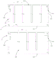
fig. 7 is a schematic diagram of the distribution of the wires of the first phase winding on the first layer, the second phase winding on the third layer and the third phase winding on the fifth layer according to an embodiment of the invention;
fig. 8 is a schematic diagram of the distribution of the first phase winding on the second layer, the second phase winding on the fourth layer and the third phase winding on the sixth layer according to the present invention.
Examples reference numbers illustrate:
| reference numerals
|
Name (R)
|
Reference numerals
|
Name (R)
|
| 10
|
Primary stage
|
11
|
PCB
|
| 111
|
Via hole
|
112
|
The first side edge
|
| 113
|
Second side edge
|
12
|
Three-phase winding
|
| 121
|
First phase winding
|
122
|
Second phase winding
|
| 123
|
Third phase winding
|
124
|
First lower conducting wire
|
| 125
|
First upper conductor
|
126
|
Second lower conducting wire
|
| 127
|
Second upper lead
|
128
|
Third lower conducting wire
|
| 129
|
Third upper conducting wire
|
114
|
First layer
|
| 115
|
Second layer
|
116
|
Third layer
|
| 117
|
The fourth layer
|
118
|
The fifth layer
|
| 119
|
The sixth layer
|
20
|
Second pole
|
| 21
|
Magnetic yoke
|
211
|
First fixing plate
|
| 212
|
Second fixing plate
|
22
|
Magnetic steel |
The implementation, functional features and advantages of the objects of the present invention will be further explained with reference to the accompanying drawings.
Detailed Description
The technical solutions in the embodiments of the present invention will be described clearly and completely with reference to the accompanying drawings in the embodiments of the present invention, and it is obvious that the described embodiments are only a partial embodiment of the present invention, and not all embodiments. All other embodiments, which can be derived by a person skilled in the art from the embodiments given herein without making any creative effort, shall fall within the protection scope of the present invention.
It should be noted that all the directional indicators (such as upper, lower, left, right, front and rear … …) in the embodiment of the present invention are only used to explain the relative position relationship, movement, etc. between the seat members in a specific posture (as shown in the drawings), and if the specific posture is changed, the directional indicator is changed accordingly.
In addition, the descriptions related to "first", "second", etc. in the present invention are for descriptive purposes only and are not to be construed as indicating or implying relative importance or implicitly indicating the number of technical features indicated. Thus, a feature defined as "first" or "second" may explicitly or implicitly include at least one such feature. In addition, technical solutions between various embodiments may be combined with each other, but must be realized by a person skilled in the art, and when the technical solutions are contradictory or cannot be realized, such a combination should not be considered to exist, and is not within the protection scope of the present invention.
The present invention proposes a linear ac permanent magnet synchronous machine, as shown in fig. 1, 2, 7 and 8, comprising a primary 10 and a secondary 20. The primary 10 comprises a PCB11 and a three-phase winding 12, the PCB11 comprising a plurality of layers of wiring, as shown in fig. 3. The PCB wiring layers are provided with a plurality of through holes 111, the through holes 111 are located at the edge of the PCB11, and the leads of the in-phase windings of the three-phase windings 12 are distributed on the two wiring layers and connected through the through holes 111. The pole pitch of the three-phase winding 12 is the same as that of the magnetic steel 22 of the secondary 20, and the span of the poles of the three-phase winding 12 is 180 electrical degrees.
Wherein the secondary 20 comprises a yoke 21 and a magnetic steel 22 mounted on the yoke 21, the magnetic steel 22 being arranged towards the primary 10. The yoke 21 plays only a magnetic field transmitting role in the magnetic circuit, and can increase the magnetic flux. The linear ac permanent magnet synchronous motor of the present embodiment may be a single-sided magnetic pole type, a double-sided magnetic pole type, a single-sided magnetic pole type having a U-shaped magnetic yoke 21, or a double-sided magnetic pole type having a U-shaped magnetic yoke 21, preferably a double-sided magnetic pole type having a U-shaped magnetic yoke 21, the U-shaped magnetic yoke 21 includes two first fixing plates 211 and a second fixing plate 212 which are oppositely disposed, and the first fixing plates 211 and the second fixing plates 212 also function as secondary magnetic yokes. Two sets of magnet steel 22 are arranged oppositely, in the two sets of magnet steel 22 arranged oppositely, one set of magnet steel 22 is arranged on one side of the first fixing plate 211 facing the second fixing plate 212, the other set of magnet steel 22 is arranged on one side of the second fixing plate 212 facing the first fixing plate 211, and the primary 10 is positioned between the two sets of magnet steel 22. The electromagnetic structure of the double-sided pole type with the U-shaped yoke 21 has a high utilization ratio for the magnetic steel 22, and the mechanical properties of the motor secondary 20 are good.
The three-phase winding 12 of the present embodiment is implemented by means of the PCB11, so that the shape of the two-dimensional winding can be made exactly according to the designed shape, and the size and thickness of the winding can be made very accurate. The three-phase armature winding of the high-density linear alternating current permanent magnet synchronous motor can be realized by fully utilizing the PCB11 technology, the manufacturing cost of the winding is low, the small linear alternating current permanent magnet synchronous motor is convenient to realize, and the motor performance is improved. The three-phase winding 12 includes a first phase winding 121, a second phase winding 122, and a third phase winding 123. The wires of the same-phase winding are respectively distributed on the two routing layers and are connected through the through holes 111 of the PCB11, and the through holes 111 for connecting the wires of the winding are positioned at the edge of the PCB11, and no through hole is arranged in the middle area of the coil, so that the space utilization rate of the PCB11 is high, and the secondary permanent magnetic steel 22 can be allowed to have more magnetic poles to reduce the edge effect of the linear motor. The air gap between the primary 10 and the secondary 20 of the motor is small, the structure of the motor is compact, and the compact small-sized linear motor is realized.
Specifically, each wire distributed on each routing layer includes a head end, a connection section, and a tail end connected in sequence, and the connection section extends according to the traveling wave structure, that is, the wires on each routing layer are spread according to a required width in a wave winding manner to form a winding magnetic pole, and the effective width of the magnetic pole is the same as the magnetic pole pitch of the secondary magnetic steel 22. The head end and the tail end of the same-phase winding are both positioned at the edge of the PCB11, so that the same-phase winding is convenient to be connected with an external circuit.
For convenience of description, the number of layers of each routing layer on PCB11 is named below, for example, the routing layer on the first layer is the first layer 114, the routing layer on the second layer is the second layer 115, and so on. More specifically, the PCB11 includes opposite first and second sides 112 and 113, and a plurality of vias 111 are disposed adjacent to the first and second sides 112 and 113, respectively. The first side 112 and the second side 113 are both located at the edge of the PCB11, the routing layers of the first layer 114 and the second layer 115 of the PCB11 are used for implementing the first phase winding 121, the distribution of the windings enables the magnetic fields of the windings on the first layer 114 and the second layer 115 to be mutually enhanced, and the effective width of the formed magnetic pole is the same as the magnetic pole pitch of the secondary magnetic steel 22. In the current flow direction in fig. 3, the first phase winding 121 has a head end located at the first layer 114 of the PCB11 and a tail end connected to the head end of the winding located at the second layer 115 by a via 111.
Referring to fig. 3 to 8, the number of layers of the routing layer of the PCB11 is 6N (N is greater than or equal to 1, N is a positive integer), and the preparation of the first phase winding 121 includes the following steps:
step one, starting from the first side 112, a first conducting wire of the first phase winding 121 extends according to a required width to form a magnetic pole, the effective width of the magnetic pole is the same as the magnetic pole pitch of the secondary magnetic steel 22, the tail end of a first lower conducting wire 124 of the first conducting wire is located at a position, close to the second side 113, of the first layer 114 of the PCB11, and is connected with the starting end of a first upper conducting wire 125 of the first conducting wire on the adjacent second layer 115 through a via hole 111 close to the second side 113;
step two, then the first upper conducting wire 125 extends on the second layer 115 from the second side 113 to the first side 112 in a wave winding manner to form a magnetic pole, the effective width of the magnetic pole is the same as the magnetic pole pitch of the secondary magnetic steel 22, the tail end of the first upper conducting wire 125 is located at the position of the second layer 115 close to the first side 112, and is connected with the head end of the second lower conducting wire 126 of the second conducting wire of the wave winding on the first layer 114 through a through hole 111 close to the first side 112;
step three, in the first layer 114, after the head end of the second lower wire 126 of the second wire is connected with the tail end of the first upper wire 125 of the second layer 115, a magnetic pole is formed in a traveling wave manner according to a required width, the effective width of the magnetic pole is the same as the magnetic pole pitch of the secondary magnetic steel 22, the tail part of the second lower conducting wire 126 is positioned close to the second side 113, and is connected to the head end of the second upper wire of the second wire on the adjacent second layer 115 through a via 111 near the second side 113, and the head end of the second upper conducting wire 127 is connected to the tail end of the second lower conducting wire 126, and is distributed in the second layer 115 towards the first side 112 in the manner of wave winding, the width of the magnetic pole is the same as the magnetic pole pitch of the secondary magnetic steel 22, the tail end of the second upper lead 127 is positioned close to the first side 112, is connected to the head end of the third lower conductor 128 of the third conductor on the first layer 114 through a via 111 near the first side 112.
And step four, repeating the step two and the step four until the wave windings of the first layer 114 and the second layer 115 of the PCB11 realize the required M conducting wires, wherein the M conducting wires on the first layer 114 and the second layer 115 are sequentially connected in series, and the current distribution of the M conducting wires can realize a magnetic field with the same width as the magnetic poles of the secondary magnetic steel.
Referring to fig. 7 and 8, the second phase winding 122 is obtained by repeating the steps from the first step to the fourth step on the third layer 116 and the fourth layer 117 of the PCB11, the width of the magnetic pole of the second phase winding 122 is the same as the width of the magnetic pole of the first phase winding 121, the second phase winding 122 is located between the first phase winding 121 and the third phase winding 123, and the space interval between the magnetic pole of the second phase winding 122 and the magnetic pole of the first phase winding 121 is 120 ° in electrical angle.
Repeating the steps one to four on the fifth layer 118 and the sixth layer 119 of the PCB11, a third phase winding 123 is obtained, the effective width of the magnetic pole of the third phase winding 123 is the same as the width of the magnetic pole of the first phase winding 121, and the spatial interval between the magnetic pole of the third phase winding 123 and the magnetic pole of the first phase winding 121 is 240 ° in electrical angle.
Preferably, the number of the three-phase windings 12 is plural, and the plural three-phase windings 12 are stacked in the thickness direction of the PCB 11. More layers can be added to realize the winding according to needs, and the preparation of the first phase winding 121, the second phase winding 122 and the third phase winding 123 is repeated on other layers of the PCB11, so that more turns can be realized on the three-phase winding 12.
In one embodiment, the first phase winding 121, the second phase winding 122, and the third phase winding 123 are electrically connected to each other to form a three-phase star topology or a three-phase delta topology. The ends of the first phase winding 121, the second phase winding 122 of the third layer 116 and the fourth layer 117, and the third phase winding 123 of the fifth layer 118 and the sixth layer 119, respectively, in the first layer 114 and the second layer 115, may be connected electrically in a Y-shape, or in a delta-shape, by suitable vias 111, and then connected to an external circuit.
The linear ac permanent magnet synchronous motor further includes a motor control circuit (not shown), a sensor circuit (not shown), and a signal processing circuit (not shown) provided on the PCB 11. The connecting socket can be arranged on the PCB11, the three-phase winding 12 on the PCB11 is connected with the motor control circuit, the sensor circuit or the signal processing circuit so as to be connected with a power supply and a circuit outside the motor system, and the circuit of the motor control circuit, the sensor circuit, the signal processing circuit and other electronic devices is arranged on the same PCB11 of the armature winding, so that the utilization rate of the motor space is improved, and the motor system is simplified.
The above description is only a preferred embodiment of the present invention, and not intended to limit the scope of the present invention, and all modifications and equivalents of the present invention, which are made by the contents of the present specification and the accompanying drawings, or directly/indirectly applied to other related technical fields, are included in the scope of the present invention.