CN1397809A - Circular polarizing disk and liquid crystal display - Google Patents
Circular polarizing disk and liquid crystal display Download PDFInfo
- Publication number
- CN1397809A CN1397809A CN02126877A CN02126877A CN1397809A CN 1397809 A CN1397809 A CN 1397809A CN 02126877 A CN02126877 A CN 02126877A CN 02126877 A CN02126877 A CN 02126877A CN 1397809 A CN1397809 A CN 1397809A
- Authority
- CN
- China
- Prior art keywords
- layer
- pair
- birefringent
- handed
- polarizers
- Prior art date
- Legal status (The legal status is an assumption and is not a legal conclusion. Google has not performed a legal analysis and makes no representation as to the accuracy of the status listed.)
- Granted
Links
Images

Classifications
-
- G—PHYSICS
- G02—OPTICS
- G02F—OPTICAL DEVICES OR ARRANGEMENTS FOR THE CONTROL OF LIGHT BY MODIFICATION OF THE OPTICAL PROPERTIES OF THE MEDIA OF THE ELEMENTS INVOLVED THEREIN; NON-LINEAR OPTICS; FREQUENCY-CHANGING OF LIGHT; OPTICAL LOGIC ELEMENTS; OPTICAL ANALOGUE/DIGITAL CONVERTERS
- G02F1/00—Devices or arrangements for the control of the intensity, colour, phase, polarisation or direction of light arriving from an independent light source, e.g. switching, gating or modulating; Non-linear optics
- G02F1/01—Devices or arrangements for the control of the intensity, colour, phase, polarisation or direction of light arriving from an independent light source, e.g. switching, gating or modulating; Non-linear optics for the control of the intensity, phase, polarisation or colour
- G02F1/13—Devices or arrangements for the control of the intensity, colour, phase, polarisation or direction of light arriving from an independent light source, e.g. switching, gating or modulating; Non-linear optics for the control of the intensity, phase, polarisation or colour based on liquid crystals, e.g. single liquid crystal display cells
- G02F1/133—Constructional arrangements; Operation of liquid crystal cells; Circuit arrangements
- G02F1/1333—Constructional arrangements; Manufacturing methods
- G02F1/1335—Structural association of cells with optical devices, e.g. polarisers or reflectors
- G02F1/13363—Birefringent elements, e.g. for optical compensation
-
- G—PHYSICS
- G02—OPTICS
- G02F—OPTICAL DEVICES OR ARRANGEMENTS FOR THE CONTROL OF LIGHT BY MODIFICATION OF THE OPTICAL PROPERTIES OF THE MEDIA OF THE ELEMENTS INVOLVED THEREIN; NON-LINEAR OPTICS; FREQUENCY-CHANGING OF LIGHT; OPTICAL LOGIC ELEMENTS; OPTICAL ANALOGUE/DIGITAL CONVERTERS
- G02F1/00—Devices or arrangements for the control of the intensity, colour, phase, polarisation or direction of light arriving from an independent light source, e.g. switching, gating or modulating; Non-linear optics
- G02F1/01—Devices or arrangements for the control of the intensity, colour, phase, polarisation or direction of light arriving from an independent light source, e.g. switching, gating or modulating; Non-linear optics for the control of the intensity, phase, polarisation or colour
- G02F1/13—Devices or arrangements for the control of the intensity, colour, phase, polarisation or direction of light arriving from an independent light source, e.g. switching, gating or modulating; Non-linear optics for the control of the intensity, phase, polarisation or colour based on liquid crystals, e.g. single liquid crystal display cells
- G02F1/133—Constructional arrangements; Operation of liquid crystal cells; Circuit arrangements
- G02F1/1333—Constructional arrangements; Manufacturing methods
- G02F1/1335—Structural association of cells with optical devices, e.g. polarisers or reflectors
- G02F1/133528—Polarisers
-
- G—PHYSICS
- G02—OPTICS
- G02F—OPTICAL DEVICES OR ARRANGEMENTS FOR THE CONTROL OF LIGHT BY MODIFICATION OF THE OPTICAL PROPERTIES OF THE MEDIA OF THE ELEMENTS INVOLVED THEREIN; NON-LINEAR OPTICS; FREQUENCY-CHANGING OF LIGHT; OPTICAL LOGIC ELEMENTS; OPTICAL ANALOGUE/DIGITAL CONVERTERS
- G02F2413/00—Indexing scheme related to G02F1/13363, i.e. to birefringent elements, e.g. for optical compensation, characterised by the number, position, orientation or value of the compensation plates
- G02F2413/02—Number of plates being 2
Landscapes
- Physics & Mathematics (AREA)
- Nonlinear Science (AREA)
- Mathematical Physics (AREA)
- Chemical & Material Sciences (AREA)
- Crystallography & Structural Chemistry (AREA)
- General Physics & Mathematics (AREA)
- Optics & Photonics (AREA)
- Polarising Elements (AREA)
- Liquid Crystal (AREA)
Abstract
在一对右旋和左旋圆偏振片的各片中,至少一个提供二分之一波长延迟的双折射层设置在偏振片和提供四分之一波长延迟的双折射层之间。提供二分之一波长延迟的双折射层的光轴与提供四分之一波长延迟的双折射层的光轴相交。在一对右旋和左旋的圆偏振片的一片上设置的双折射层在数量上与另一片上的双折射层的数量相等。对于波长为200到1000nm的范围内的部分或全部波长,圆偏振片的双折射层全部提供四分之一波长的延迟。当一对圆偏振片相对设置时,圆偏振片包括的双折射层以距偏振片的距离为序从第一层编号排到第n层,圆偏振片包括的偏振片分别位于外侧,第一层的快轴之间的交叉角,第二层的快轴之间的交叉角,……,第n层的快轴之间的交叉角和一对圆偏振片的偏振片的透射轴之间交叉角的角度在80到100度的范围内。
In each of a pair of right-handed and left-handed circular polarizers, at least one birefringent layer providing one-half wavelength retardation is disposed between the polarizer and the birefringent layer providing quarter-wave retardation. The optical axis of the birefringent layer providing one-half wavelength retardation intersects the optical axis of the birefringent layer providing quarter wavelength retardation. The number of birefringent layers provided on one of a pair of right-handed and left-handed circular polarizers is equal to the number of birefringent layers on the other. The birefringent layers of the circular polarizer all provide a quarter wavelength retardation for some or all of the wavelengths in the wavelength range of 200 to 1000 nm. When a pair of circular polarizers are arranged opposite to each other, the birefringent layers included in the circular polarizer are numbered from the first layer to the nth layer in order of distance from the polarizer, and the polarizers included in the circular polarizer are respectively located on the outside, and the first The cross angle between the fast axes of the layers, the cross angle between the fast axes of the second layer, ..., the cross angle between the fast axes of the nth layer and the transmission axes of the polarizers of a pair of circular polarizers The angle of the intersection angle is in the range of 80 to 100 degrees.
Description
本发明申请基于日本公开特许公报No.2001-216147,本文引用参考其内容。The present application is based on Japanese Laid-Open Patent Publication No. 2001-216147, the content of which is incorporated herein by reference.
技术领域technical field
本发明涉及一对右旋和左旋圆偏振片,其提供了很宽波长范围的圆偏振光,右旋和左旋圆偏振片可以联合使用,用于形成高对比度的液晶显示装置。The invention relates to a pair of right-handed and left-handed circular polarizers, which provide circularly polarized light with a wide wavelength range. The right-handed and left-handed circular polarizers can be used in combination to form a high-contrast liquid crystal display device.
背景技术Background technique
对于由四分之一波长片和偏振片叠层构成的一对右旋和左旋圆偏振片,迄今知道存在一种组件,其中各四分之一波长片的光轴(慢轴或快轴)用作固定系统,由此,各个偏振片的吸收轴或透射轴(偏振轴)设置成可相互转动90度。对于用于一对偏振片的各片中的四分之一波长片,已经知道有一种四分之一波长片由层叠的多个双折射层构成,故双折射层的光轴互相相交,四分之一波长片形成的圆偏振光具有很宽的波长范围(见日本公开特许公报昭和5-100114,日本公开特许公报昭和11-231132,日本公开特许公报NO.2001-4837等)。For a pair of right-handed and left-handed circular polarizers composed of a quarter-wavelength plate and a laminate of polarizers, it is known so far that there is a component in which the optical axis (slow axis or fast axis) of each quarter-wavelength plate Used as a fixed system whereby the absorption or transmission axes (polarization axes) of the individual polarizers are arranged to be rotatable by 90 degrees relative to each other. For the quarter-wavelength plate in each plate used for a pair of polarizers, it is known that there is a quarter-wavelength plate consisting of a plurality of birefringent layers stacked so that the optical axes of the birefringent layers intersect each other, and the four The circularly polarized light formed by the one-wavelength plate has a wide wavelength range (see Japanese Laid-Open Patent Publication Showa 5-100114, Japanese Laid-Open Patent Publication Showa 11-231132, Japanese Laid-Open Patent Publication No. 2001-4837, etc.).
一对右旋和左旋圆偏振片分别设置在液晶显示装置的两侧,如τ型,其利用前延迟几乎为零的状态,以实现高对比度或类似性能。然而,其存在难以避免形成黑色状态的问题,即使在使用一对右旋或左旋圆偏振片导致左旋圆偏振光和右旋圆偏振光互相重叠的情况下。这个问题造成对比度降低,因为当一对圆偏振片固定在液晶显示装置上时,黑色显示出现漏光。A pair of right-handed and left-handed circular polarizers are respectively arranged on both sides of the liquid crystal display device, such as τ type, which utilizes the state of almost zero front retardation to achieve high contrast or similar performance. However, there is a problem that it is difficult to avoid the formation of a black state even in the case where a pair of right-handed or left-handed circular polarizers is used so that left-handed circularly polarized light and right-handed circularly polarized light overlap each other. This problem causes a decrease in contrast because light leakage occurs in a black display when a pair of circular polarizing plates is fixed on a liquid crystal display device.
发明内容Contents of the invention
本发明的目的是得到一对右旋和左旋圆偏振片,当左旋圆偏振光和右旋偏振光互相量叠时可形成良好的黑色状态,可用于形成高对比度的液晶显示装置。The object of the present invention is to obtain a pair of right-handed and left-handed circular polarizers, which can form a good black state when the left-handed circularly polarized light and the right-handed polarized light are superimposed on each other, and can be used to form a high-contrast liquid crystal display device.
根据本发明,提供了一对右旋和左旋圆偏振片,各圆偏振片具有:偏振片,提供四分之一波长延迟的双折射层,和至少一个提供二分之一波长延迟的双折射层,设置在所述偏振片和所述提供四分之一波长延迟的双折射层之间;故所述提供二分之一波长延迟的双折射层的光轴与所述提供四分之一波长延迟的双折射层的光轴相交,其中,在所述一对右旋和左旋的圆偏振片中的一片设置的所述双折射层在数量上与另一片的所述双折射层的数量相等,对于波长为200到1000nm范围内的部分或全部波长,所述一对圆偏振片的各片包括的双折射层全部提供四分之一波长的延迟;当所述一对圆偏振片相对设置时,所述一对圆偏振片各片包括的双折射层以距离偏振片的距离为序从第一层编号排到第n层,所述一对圆偏振片包括的偏振片分别位于外侧,第一层的快轴之间的交叉角,第二层的快轴之间的交叉角,......,第n层的快轴之间的交叉角和所述一对圆偏振片的所述偏振片的透射轴之间的交叉角的角度在80到100度的范围内。According to the present invention, there is provided a pair of right-handed and left-handed circular polarizers, each circular polarizer having: a polarizer, a birefringent layer providing a quarter-wave retardation, and at least one birefringent layer providing a half-wave retardation layer, arranged between the polarizer and the birefringent layer providing quarter-wave retardation; so the optical axis of the birefringent layer providing quarter-wave retardation The optical axes of the wavelength retarding birefringent layers intersect, wherein the number of the birefringent layers provided on one of the pair of right-handed and left-handed circular polarizing plates is the same as that of the other one. Equal, for part or all of the wavelengths within the wavelength range of 200 to 1000nm, the birefringent layers included in each of the pair of circular polarizing plates all provide a quarter-wavelength retardation; when the pair of circular polarizing plates are opposite to each other When setting, the birefringent layers included in each sheet of the pair of circular polarizers are numbered from the first layer to the nth layer in order of distance from the polarizer, and the polarizers included in the pair of circular polarizers are respectively located on the outside , the crossing angle between the fast axes of the first layer, the crossing angle between the fast axes of the second layer, ... , the crossing angle between the fast axes of the nth layer and the pair of circular polarizations The angle of intersection between the transmission axes of the polarizers of the sheet is in the range of 80 to 100 degrees.
另外,根据本发明,提供了液晶显示装置,其具有:液晶显示单元;和一对如上定义的右旋和左旋圆偏振片,分开设置在所述液晶单元的两侧,使一对圆偏振片包括的所述偏振片分别位于外侧;其中,设置在所述液晶单元的相对侧的所述一对圆偏振片的各片包括的所述双折射层以距所述折射层的距离为序从第一层编号排到第n层,所述第一层的快轴之间的交叉角、所述第二层的快轴之间的交叉角、......所述第n层的快轴之间的交叉角和所述一对圆偏振片的所述偏振片的透射轴之间的交叉角的角度在80到100度的范围内。In addition, according to the present invention, a liquid crystal display device is provided, which has: a liquid crystal display unit; and a pair of right-handed and left-handed circular polarizers as defined above, which are separately arranged on both sides of the liquid crystal unit, so that the pair of circular polarizers The included polarizers are located outside respectively; wherein, the birefringent layers included in each sheet of the pair of circular polarizers arranged on opposite sides of the liquid crystal cell are in order of distance from the refraction layer from The first layer is numbered to the nth layer, the intersection angle between the fast axes of the first layer, the intersection angle between the fast axes of the second layer, ... the nth layer An angle of a crossing angle between fast axes and a crossing angle between transmission axes of the polarizing plates of the pair of circular polarizing plates is in a range of 80 to 100 degrees.
根据本发明,得到了一对右旋和左旋圆偏振片,当左旋圆偏振光和右旋偏振光互相重叠时,可形成良好黑色状态,这可用于形成高对比度液晶显示装置。这是基于通过对短波长侧和长波长侧进行轻微变形以防止各圆偏振片产生的圆偏振光转换成椭圆偏振光的一种技术。According to the present invention, a pair of right-handed and left-handed circular polarizers is obtained. When left-handed circularly polarized light and right-handed polarized light overlap each other, a good black state can be formed, which can be used to form a high-contrast liquid crystal display device. This is a technique based on preventing the circularly polarized light generated by each circularly polarizing plate from being converted into elliptically polarized light by slightly deforming the short-wavelength side and the long-wavelength side.
即,本发明人经过努力研究,克服了液晶显示装置的对比度下降的问题。所述显示装置使用一对左旋和右旋的圆偏振片,偏振片设置成使一对圆偏振片包括的偏振片的透射轴分别相对转动90度。其结果是,发现了对比度减少的原因是由于通过在短波长侧和长波长侧产生轻微变形造成方位角位移因此破坏了透射轴的正交性,各偏振片产生的圆偏振光转换成椭圆偏振光。That is, the inventors of the present invention have overcome the problem of the decrease in the contrast of the liquid crystal display device as a result of diligent research. The display device uses a pair of left-handed and right-handed circular polarizers, and the polarizers are arranged so that the transmission axes of the polarizers included in the pair of circular polarizers are relatively rotated by 90 degrees. As a result, it was found that the reason for the decrease in contrast is that the circularly polarized light generated by each polarizing plate is converted into elliptically polarized light due to the azimuthal shift caused by slight deformation on the short-wavelength side and the long-wavelength side, thereby destroying the orthogonality of the transmission axis Light.
本发明的特征和优点将通过下面结合附图对优选实施例的详细介绍有更清楚的介绍。The features and advantages of the present invention will be more clearly introduced through the following detailed description of preferred embodiments in conjunction with the accompanying drawings.
附图说明。 Description of drawings .
图1显示了一对圆偏振片的示例。Figure 1 shows an example of a pair of circular polarizers.
具体实施方式Detailed ways
根据本发明的一对圆偏振片是一对右旋和左旋圆偏振片,各偏振片具有:偏振片,提供四分之一波长延迟的双折射层,和至少一个提供二分之一波长延迟的双折射层,设置在所述偏振片和所述提供四分之一波长延迟的双折射层之间;故所述提供二分之一波长延迟的双折射层的光轴与所述提供四分之一波长延迟的双折射层的光轴相交,其中,在所述一对右旋和左旋的圆偏振片中的一片设置的所述双折射层在数量上与另一片的所述双折射层的数量相等,对于波长为200到1000nm范围内的部分或全部波长,所述一对圆偏振片的各片包括的双折射层全部提供四分之一波长的延迟;当所述一对圆偏振片相对设置时,所述一对圆偏振片各片包括的双折射层以距离偏振片的距离为序从第一层编号排到第n层,所述一对圆偏振片包括的偏振片分别位于外侧,第一层的快轴之间的交叉角,第二层的快轴之间的交叉角,......,第n层的快轴之间的交叉角和所述一对圆偏振片的所述偏振片的透射轴之间的交叉角的角度在80到100度的范围内。A pair of circular polarizing plates according to the present invention is a pair of right-handed and left-handed circular polarizing plates, each polarizing plate having: a polarizing plate, a birefringent layer providing a quarter-wave retardation, and at least one providing a half-wave retardation A birefringent layer is arranged between the polarizer and the birefringent layer providing a quarter wavelength retardation; so the optical axis of the birefringent layer providing a quarter wavelength retardation and the providing four The optical axes of the one-wavelength retarded birefringent layers intersect, wherein the birefringent layers provided on one of the pair of right-handed and left-handed circular polarizing plates are equal in number to the birefringent layers of the other plate The number of layers is equal, and for part or all of the wavelengths within the range of 200 to 1000 nm, the birefringence layers included in each of the pair of circular polarizers all provide a quarter-wavelength retardation; when the pair of circular polarizers When the polarizers are arranged oppositely, the birefringent layers included in each sheet of the pair of circular polarizers are numbered from the first layer to the nth layer in order of distance from the polarizers, and the polarizers included in the pair of circular polarizers Respectively located on the outside, the intersection angle between the fast axes of the first layer, the intersection angle between the fast axes of the second layer, ..., the intersection angle between the fast axes of the nth layer and the first layer The angle of intersection between the transmission axes of the polarizing plates for the circular polarizing plate is in the range of 80 to 100 degrees.
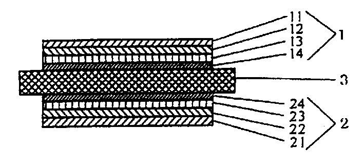
图1显示了一对圆偏振片的示例。在图1中,标记1表示一对右旋和左旋圆偏振片中的一个,2表示一对右旋和左旋圆偏振片中的另一个。11和21是偏振片,12、13、22和23是提供了二分之一波长延迟的双折射层,14和24是提供了二分之一波长延迟的双折射层。顺便提到,图1显示了一对圆偏振片应用到液晶显示装置上的情况。参考标记3表示液晶显示单元。Figure 1 shows an example of a pair of circular polarizers. In FIG. 1,
如图1所示,一对右旋和左旋圆偏振片1和2的各片包括偏振片11或21,提供四分之一波长延迟的双折射层14或24,提供二分之一波长延迟的一个、两个或多个双折射层12和13或22和23。双折射层12和13或22和23设置在偏振片11或12和双折射层14或24之间,故双折射层12和13或22和23的光轴与提供四分之一波长延迟的双折射层14或24的光轴相交。一对右旋和左旋圆偏振片中的一片设置的双折射层的数量与另一个片的双折射层的数量相等,所以一对右旋和左旋圆偏振片的各片包括的多个双折射层在从200到1000nm的部分或全部波长范围内全部提供四分之一波长延迟。As shown in Figure 1, each of a pair of right-handed and left-handed
可以使用适当的材料来构成各圆偏振片的偏振片和双折射层,可用的材料在种类上没有特别限制,顺便提到,偏振片使用能够透射线性偏振光但吸收其它光的适当材料。偏振片材料的示例包括:通过拉伸亲水的高分子膜得到的偏振膜,如聚乙烯醇薄膜、部分缩甲醛化的聚乙烯醇薄膜或通过亲水高分子膜吸收碘和/或二色性的染料后部分皂化的乙烯乙酸乙烯酯共聚物膜、和通过前面提到的方式得到的偏振薄膜并设置了一层透明的保护层,以保护偏振薄膜的一个或两个相对表面。Appropriate materials can be used to constitute the polarizing plate and the birefringent layer of each circular polarizing plate, and usable materials are not particularly limited in kind, and incidentally, suitable materials capable of transmitting linearly polarized light but absorbing other light are used for the polarizing plate. Examples of polarizer materials include polarizing films obtained by stretching hydrophilic polymer films such as polyvinyl alcohol films, partially formalized polyvinyl alcohol films, or absorption of iodine and/or dichroism by hydrophilic polymer films Partially saponified ethylene vinyl acetate copolymer film after permanent dye, and the polarizing film obtained by the above-mentioned way and set a transparent protective layer to protect one or two opposite surfaces of the polarizing film.
透明保护层可用适当的聚合物形成,特别地,透明保护层最好用具有优良的透明度、机械强度、热稳定性和湿气密封性等性能的聚合物来形成。透明的保护层可以通过适当的方法来形成,如应用聚合物液体的方法或将薄膜材料粘结或叠层的方法。The transparent protective layer can be formed with an appropriate polymer, and in particular, the transparent protective layer is preferably formed with a polymer having excellent properties such as transparency, mechanical strength, thermal stability, and moisture-tightness. The transparent protective layer can be formed by an appropriate method such as a method of applying a polymer liquid or a method of bonding or laminating film materials.
顺便提到,聚合物的示例包括:纤维素基聚合物,如二乙酰纤维素和三乙酰纤维素;聚酯基聚合物,如聚对苯二甲酸乙二醇酯和聚萘二甲酸乙二醇酯;烯烃基聚合物,如聚乙烯、聚丙烯、环基或降冰片烯结构聚烯烃和乙烯-丙烯共聚物;酰胺基聚合物,如尼龙和芳香族聚酰胺;聚碳酸酯基聚合物,丙烯基聚合物,如聚甲基丙烯酸甲酯;和苯乙烯基聚合物,如聚苯乙烯和丙烯腈/苯乙烯共聚物。Incidentally, examples of polymers include: cellulose-based polymers such as diacetyl cellulose and triacetyl cellulose; polyester-based polymers such as polyethylene terephthalate and polyethylene naphthalate; Alcohol esters; Olefin-based polymers, such as polyethylene, polypropylene, cyclo- or norbornene-structured polyolefins and ethylene-propylene copolymers; Amide-based polymers, such as nylon and aramid; Polycarbonate-based polymers , acrylic-based polymers, such as polymethyl methacrylate; and styrene-based polymers, such as polystyrene and acrylonitrile/styrene copolymers.
用于形成透明保护层的聚合物的示例还包括:酰亚胺基聚合物,砜基聚合物,聚醚砜基聚合物,聚醚醚酮基聚合物,聚亚苯基硫醚基聚合物,乙烯醇基聚合物,烯丙基聚合物,聚甲醛基聚合物,环氧基聚合物,乙烯基丁醛和前面提到聚合物的混合物。以及能够通过加热或紫外光辐射固化的聚合物,如聚酯基聚合物,丙烯基聚合物,聚氨酯基聚合物,酰胺基聚合物,硅酮基聚合物,环氧基聚合物。特别地,优选使用一种在各向同性性能上非常好的薄膜如三乙酰纤维素薄膜。Examples of the polymer used to form the transparent protective layer also include imide-based polymers, sulfone-based polymers, polyethersulfone-based polymers, polyether ether ketone-based polymers, polyphenylene sulfide-based polymers , vinyl alcohol-based polymers, allyl polymers, polyoxymethylene-based polymers, epoxy-based polymers, vinyl butyral and mixtures of the aforementioned polymers. And polymers that can be cured by heat or UV radiation, such as polyester-based polymers, acrylic-based polymers, polyurethane-based polymers, amide-based polymers, silicone-based polymers, epoxy-based polymers. In particular, it is preferable to use a film which is very good in isotropic properties such as a triacetylcellulose film.
在另一方面,各种双折射层材料的示例包括:通过折射率各向不同的材料的定向和固定而得到的单层,通过对各向同性或各向不同性的基本材料涂复折射率各向不同的材料并定向及固定折射率各向不同材料得到的多层。折射率各向不同的材料的示例包括:液晶材料,如discotic液晶聚合物,向列液晶聚合物,或高分子液晶和无机材料。双折射层的另一示例是由受到适当定向工艺处理的薄膜构成的双折射层,如单轴或双轴拉伸的用与形成透明保护层相同的聚合物形成的聚合物薄膜。双折射层的另一示例是其厚度方向透射率由在粘结到热收缩薄膜时提供收缩力或/和拉伸力的方法进行控制的聚合物薄膜构成的双折射层。双折射层最好具有优良的折射率(透光率)。On the other hand, examples of various birefringent layer materials include: monolayers obtained by the orientation and fixation of materials with anisotropic refractive indices, by coating isotropic or anisotropic base materials with Multilayers obtained by different materials and orientation and fixation of materials with different refractive indices. Examples of materials with anisotropic refractive indices include liquid crystal materials such as discotic liquid crystal polymers, nematic liquid crystal polymers, or polymeric liquid crystals and inorganic materials. Another example of a birefringent layer is one formed from a film subjected to an appropriate orientation process, such as a uniaxially or biaxially stretched polymer film formed from the same polymer used to form the transparent protective layer. Another example of the birefringent layer is a birefringent layer composed of a polymer film whose thickness-direction transmittance is controlled by a method of providing shrinkage force or/and stretching force when bonded to a heat-shrinkable film. The birefringent layer preferably has an excellent refractive index (light transmittance).
根据抑制由于应力造成的延迟改变的观点优选的双折射层,对于波长为633nm的光,其光弹性系数不大于5×10-11m2/N,一般不大于1×10-11m2/N,最好不大于7×10-11m2/N。从上面列出的液晶材料制成的双折射层最好根据能得到光弹系数来优选,因为一般这些双折射层的光弹性系数很小,偏振片的变形造成延迟改变或快轴改变过于小不能使对比度减小。在聚合物薄膜形成的双折射层中,烯基聚合物,尤其是如降冰片烯基聚合物、乙酰纤维素基聚合物、聚甲基丙烯酸甲酯基聚合物等是最合适的,这是基于双折射层的双折射率与波长的相关性,双折射层的光弹性,和抑制双折射层和用于层压的粘结剂之间折射率的差别造成的界面反射的光弹系数的考虑。A preferred birefringent layer from the viewpoint of suppressing retardation changes due to stress has a photoelastic coefficient of not more than 5×10 -11 m 2 /N, generally not more than 1×10 -11 m 2 /N for light having a wavelength of 633 nm N is preferably not greater than 7×10 -11 m 2 /N. Birefringent layers made from the liquid crystal materials listed above are best selected according to the photoelastic coefficients that can be obtained, because generally the photoelastic coefficients of these birefringent layers are very small, and the deformation of the polarizer causes a retardation change or a fast axis change that is too small The contrast cannot be reduced. Among the birefringent layers formed by polymer films, alkenyl polymers, especially norbornene-based polymers, acetylcellulose-based polymers, polymethyl methacrylate-based polymers, etc. are most suitable, which is Based on the wavelength dependence of the birefringence of the birefringent layer, the photoelasticity of the birefringent layer, and the photoelastic coefficient for suppressing interfacial reflection caused by the difference in refractive index between the birefringent layer and the adhesive used for lamination consider.
对于双折射层,提供了四分之一波长延迟的双折射层和提供了二分之一波长延迟的双折射层组合使用。双折射层组合在波长从200到1000nm的部分或全部范围内全部提供四分之一波长的延迟。在这种情况下,提供二分之一波长延迟的双折射层设置在偏振片和提供四分之一波长延迟的双折射层之间。提供了二分之一波长延迟的双折射层可以由一层或多层构成。提供了二分之一波长延迟的双折射层中的层数一般不大于4,尤其不大于3,但也可以是5或更大。For the birefringent layer, a birefringent layer providing a quarter wavelength retardation and a birefringent layer providing a half wavelength retardation are used in combination. The combination of birefringent layers provides a quarter wavelength retardation all over part or all of the wavelength range from 200 to 1000 nm. In this case, the birefringent layer providing a half-wave retardation is disposed between the polarizer and the birefringent layer providing a quarter-wave retardation. The birefringent layer providing one-half wavelength retardation may consist of one or more layers. The number of layers in the birefringent layer providing a half wavelength retardation is generally not more than 4, especially not more than 3, but may be 5 or more.
构成圆偏振片的双折射层可以由一种材料形成或由不同的材料形成。当双折射层由一种材料形成时,用作相对某些波长光的二分之一延迟片的双折射叠层和用作相对这些光的四分之一波长延迟片的双折射叠层可以组合在一起,所以两个叠层在色散特征上具有同样的取决波长的折射率或双折射率。当双折射层由不同的材料形成时,双折射叠层可进行组合,所以叠层在色散特征上具有不同的取决波长的折射率或双折射率。The birefringent layers constituting the circular polarizing plate may be formed of one material or of different materials. When the birefringent layer is formed of one material, the birefringent stack serving as a half retarder for certain wavelengths of light and the birefringent stack serving as a quarter wavelength retarder for those light can be combined so that both stacks have the same wavelength-dependent refractive index or birefringence in terms of dispersion characteristics. Birefringent stacks can be combined when the birefringent layers are formed from different materials so that the stacks have different wavelength-dependent refractive indices or birefringence in terms of dispersion characteristics.
各个双折射层可以由单层或多个延迟膜的叠层构成以调整双折射层的延迟特性。在后一种情况下,将进行层压的延迟膜可以分别由一种材料或不同种的材料形成。顺便提及,由各个双折射层提供的四分之一或二分之一波长延迟可以通过适当的方法进行控制,比如改变各层的材料,层的厚度和各层定向条件的方法,或如上所述的层压方法。当双折射层的光轴的方向改变时,各双折射层的慢轴或类似轴根据光轴的平均方向来确定。Each birefringent layer may be composed of a single layer or a stack of a plurality of retardation films to adjust the retardation characteristics of the birefringent layer. In the latter case, the retardation films to be laminated may be formed of one material or different materials, respectively. Incidentally, the one-quarter or one-half wavelength retardation provided by each birefringent layer can be controlled by an appropriate method, such as a method of changing the material of each layer, the thickness of the layer and the orientation condition of each layer, or as above The lamination method described. When the direction of the optical axis of the birefringent layer changes, the slow axis or the like of each birefringent layer is determined based on the average direction of the optical axis.
如上所述在从200到1000nm的部分或全部的波长范围内全部提供四分之一波长延迟的双折射层组合可在下面的条件下形成,提供相对上述波长范围中一个波长延迟四分之一波长的双折射层和至少一个双折射层,特别是相对波长范围内另一个波长延迟二分之一波长的多个双折射层,以各种组合进行层压;或双折射层的光轴之间交叉角被改变。顺便提一下,在上述波长的部分或全部范围内提供四分之一波长延迟的双折射层组合的情况下,考虑到显示特性,该波长范围的部分最好不小于200到1000nm的波长范围的50%,尤其是不小于60%,最好是不小于70%。The combination of birefringent layers providing a quarter-wavelength retardation all over part or all of the wavelength range from 200 to 1000 nm as described above can be formed under the following conditions to provide a quarter-wavelength retardation with respect to one wavelength in the above-mentioned wavelength range wavelength birefringent layers and at least one birefringent layer, in particular a plurality of birefringent layers retarded by one-half wavelength relative to another wavelength in the wavelength range, laminated in various combinations; or between the optical axes of the birefringent layers The intersection angle is changed. Incidentally, in the case of a combination of birefringent layers providing a quarter-wave retardation in part or all of the above-mentioned wavelength range, it is preferable that part of the wavelength range is not less than that of the wavelength range of 200 to 1000 nm in view of display characteristics. 50%, especially not less than 60%, preferably not less than 70%.
根据本发明的一对圆偏振片以右旋和左旋圆偏振片的组合形式应用,其中一片设置了双折射层,其数量等于另一个片的双折射层的数量。各圆偏振片包括偏振片、提供四分之一波长延迟的双折射层、和至少一个提供二分之一波长延迟的双折射层,所以提供二分之一波长延迟的双折射层的光轴与提供四分之一波长延迟的双折射层的光轴相交。当一对圆偏振片的两片相对设置时,一对圆偏振片的各片包括的双折射层以距偏振片的距离为序从第一层编号排到n层,所以一对圆偏振片中的偏振片分别位于外侧,第一层的快轴之间的交叉角,第二层的快轴之间的交叉角,......,第n层的快轴之间的交叉角和所述一对圆偏振片的所述偏振片的透射轴之间的交叉角的角度在80到100度的范围内,特别是在85到95度的范围内。顺便提到,相对的双折射层的快轴之间的交叉关系和偏振片的透射轴之间的交叉关系可以被对应的双折射层的慢轴之间的交叉关系和偏振片的吸收轴之间的交叉关系所取代。A pair of circular polarizing plates according to the present invention is used in combination of right-handed and left-handed circular polarizing plates, one of which is provided with birefringent layers equal to the number of birefringent layers of the other plate. Each circular polarizer comprises a polarizer, a birefringent layer providing one-quarter wavelength retardation, and at least one birefringent layer providing one-half wavelength retardation such that the optical axis of the birefringent layer providing one-half wavelength retardation Intersects the optical axis of the birefringent layer that provides quarter-wave retardation. When two sheets of a pair of circular polarizers are arranged oppositely, the birefringent layers included in each sheet of a pair of circular polarizers are numbered from the first layer to n layers in order of distance from the polarizer, so a pair of circular polarizers The polarizers in are located on the outside respectively, the crossing angle between the fast axes of the first layer, the crossing angle between the fast axes of the second layer, ..., the crossing angle between the fast axes of the nth layer The angle of intersection with the transmission axes of the polarizing plates of the pair of circular polarizing plates is in the range of 80 to 100 degrees, particularly in the range of 85 to 95 degrees. Incidentally, the cross relationship between the fast axes of the opposing birefringent layers and the transmission axis of the polarizer can be compared to the cross relationship between the slow axes of the corresponding birefringent layers and the absorption axis of the polarizer replaced by cross-relationships.
交叉关系可以如下所示来取得。例如,当θ0是偏振片的吸收轴的角度时,θ1......和θ(n-1)是根据双折射层安排的层号提供二分之一波长延迟的双折射层的慢轴的各个角度,θn是提供四分之一波长延迟的双折射层的慢轴的角度,圆偏振片根据下列条件形成,即提供二分之一波长延迟的双折射层的慢轴的角度和提供四分之一波长延迟的双折射层的慢轴的角度分别由下列表达式1和2来确定。表达式1:The cross relationship can be obtained as shown below. For example, when θ0 is the angle of the absorption axis of the polarizer, θ1... and θ(n-1) are the slowness of the birefringent layer that provides a half-wavelength retardation according to the layer number of the birefringent layer arrangement. Each angle of the axis, θn is the angle of the slow axis of the birefringent layer that provides a quarter-wave retardation, and the circular polarizer is formed according to the following conditions, that is, the angle of the slow axis of the birefringent layer that provides a half-wave retardation and The angles of the slow axes of the birefringent layers providing quarter-wave retardation are determined by the following
θ0+2×θ1+......2×θ(n-2)+θ(n-1) 或θ0+2×θ1+......2×θ(n-2)+θ(n-1) or
θ0-2×θ1-......2×θ(n-2)-θ(n-1)表达式2:θ0-2×θ1-...2×θ(n-2)-θ(n-1) Expression 2:
θ0+2×θ1+......2×θ(n-1)+45度 或θ0+2×θ1+......2×θ(n-1)+45 degrees or
θ0-2×θ1-......2×θ(n-1)-45度θ0-2×θ1-......2×θ(n-1)-45 degrees
另一圆偏振片根据下列条件形成,即80到100度的角度范围施加到偏振片的吸收轴的各角度和圆偏振片上的双折射层的延迟轴的角度后,由于反转而产生的改正要加到各角度。Another circular polarizing plate is formed under the condition that after applying an angle range of 80 to 100 degrees to each angle of the absorption axis of the polarizing plate and the angle of the retardation axis of the birefringent layer on the circular polarizing plate, the correction due to inversion to be added to each angle.
顺便提及,当某一层用作提供二分之一波长延迟的双折射层时,在圆偏振片中提供二分之一波长延迟的双折射层的慢轴的角度根据表达式1计算,为θ0+θ1或θ0-θ1。提供四分之一波长延迟的双折射层的慢轴的角度因此根据表达式2计算,为θ0+2×θ1+45度或θ0-2×θ1-45度。在这种情况下,偏振片的吸收轴的角度θ0是任意的,角度θ1最好在5到25度的范围内。Incidentally, when a certain layer is used as a birefringent layer providing a half-wave retardation, the angle of the slow axis of the birefringent layer providing a half-wave retardation in a circular polarizing plate is calculated according to
另一方面,当两层用作提供二分之一波长延迟的双折射层时,在偏振片中提供二分之一波长延迟的第一和第二双折射层的慢轴的角度分别根据表达式1进行计算,为θ0+θ1或θ0-θ1(第一层)和θ0+2×θ1+θ2或θ0-2×θ1-θ2(第二层)。因此提供四分之一波长延迟的双折射层(第三)的慢轴的角度根据表达式2计算,为θ0+2×θ1+2×θ2+45度或θ0-2×θ1-2×θ2-45度。在这种情况下,偏振片的吸收轴的角度θ0是任意的,角度θ1和θ2最好分别在5到15度的范围和10到30度的范围内。On the other hand, when two layers are used as the birefringent layer providing the half-wave retardation, the angles of the slow axes of the first and second birefringent layers providing the half-wave retardation in the polarizing plate are respectively expressed according to
另外,当三层用作提供二分之一波长延迟的双折射层时,在偏振片中提供二分之一波长延迟的第一、第二和第三双折射层的慢轴的角度分别根据表达式1进行计算,为θ0+θ1或θ0-θ1(第一层),θ0+2×θ1+θ2或θ0-2×θ1-θ2(第二层)和θ0+2×θ1+2×θ2+θ3或θ0-2×θ1-2×θ2-θ3(第三层)。因此提供四分之一波长延迟的双折射层(第四)的慢轴的角度根据表达式2计算,为θ0+2×θ1+2×θ2+2×θ3+45度或θ0-2×θ1-2×θ2-2×θ3-45度。在这种情况下,偏振片的吸收轴的角度θ0是任意的,角度θ1、θ2和θ3最好分别在1到10度的范围、10到30度的范围和20到60度的范围内。In addition, when three layers are used as a birefringent layer providing a half-wave retardation, the angles of the slow axes of the first, second, and third birefringent layers providing a half-wave retardation in a polarizing plate are respectively determined according to
顺便提及,各个圆偏振片中的偏振片和各个双折射层可以简单地一个放置在另一个之上,或根据防止光轴位移和被灰尘污染的考虑最好一个粘结到另一个上面。考虑到除由于防止光轴位移而稳定了质量外还可提高装配液晶显示装置的效率,形成各个圆偏振片最好通过对材料进行整体层压。Incidentally, the polarizing plates and the respective birefringent layers in the respective circular polarizing plates may simply be placed one on top of the other, or preferably bonded one to the other from the viewpoint of preventing displacement of the optical axis and contamination by dust. In consideration of improving the efficiency of assembling the liquid crystal display device in addition to the quality stabilization due to the prevention of optical axis displacement, it is preferable to form the individual circular polarizing plates by integrally laminating the materials.
粘结工艺可以通过适当的方法来进行,如使用透明的粘结剂或胶粘剂。对粘结剂的种类没有特别的限制。优选采用不要求高温加热工艺来进行固化和干燥,也不要求长时间固化和干燥工艺的粘结剂以防止偏振片和双折射层的光学特性发生改变。另外,最好使用具有在通过粘结剂进行层压的材料的折射率之间的中间折射率的粘结剂以抑制界面反射。The bonding process can be performed by an appropriate method, such as using a transparent adhesive or adhesive. There is no particular limitation on the kind of binder. It is preferable to use an adhesive that does not require a high-temperature heating process for curing and drying, and does not require a long-time curing and drying process to prevent changes in optical characteristics of the polarizing plate and the birefringent layer. In addition, it is preferable to use an adhesive having an intermediate refractive index between those of materials to be laminated by the adhesive to suppress interfacial reflection.
如果有必要,粘结剂层可以设置在各个圆偏振片上以便圆偏振片可通过粘结剂层粘结到主体上,如液晶显示装置。当粘结剂层暴露在表面时,粘结剂层的暴露表面可暂时地用施加保护的如可防止污染的分隔件覆盖,直到粘结剂层投入实际使用。当用于形成圆偏振片的一种材料暴露于表面时,材料的暴露表面可以用表面保护膜粘性地覆盖,使得材料可以免于损伤。If necessary, an adhesive layer may be provided on each circular polarizing plate so that the circular polarizing plate can be bonded to a main body such as a liquid crystal display device through the adhesive layer. When the adhesive layer is exposed on the surface, the exposed surface of the adhesive layer may be temporarily covered with a protective, such as a stain-proof separator, until the adhesive layer is put into actual use. When one of the materials used to form the circular polarizing plate is exposed to the surface, the exposed surface of the material may be adhesively covered with a surface protection film so that the material may be protected from damage.
根据本发明的一对圆偏振片可以根据相关技术用于各种不同的目的。一对圆偏振片最好用于形成可实现高对比度的液晶显示装置,例如τ型,其特别利用了一种前延迟基本为零的状态。液晶显示装置可用这种方式形成,即一对右旋和左旋圆偏振片1和2分开设置在液晶显示单元3的两侧,故一对圆偏振片1和2中的偏振片11和21分别位于外侧,如图1所示。A pair of circular polarizing plates according to the present invention can be used for various purposes according to the related art. A pair of circular polarizers is preferably used to form a liquid crystal display device capable of high contrast, such as the Tau type, which specifically utilizes a state in which the front retardation is substantially zero. The liquid crystal display device can be formed in this way, that is, a pair of right-handed and left-handed
在一对圆偏振片1和2以前面提到的方式设置在液晶显示单元3的两侧的情况下,当一对圆偏振片1和2中的双折射层根据距偏振片的距离从第一层编号排到第n层时,在一对圆偏振片1和2中的双折射层和偏振片设置成使得第一层12和22的快轴(慢轴)之间的交叉角,第二层13和23的快轴(慢轴)之间的交叉角,第三层14和24的快轴(慢轴)之间的交叉角......第n层的快轴(慢轴)之间的交叉角,和在一对圆偏振片中的偏振片的透射轴(吸收轴)之间的交叉角处于80到100度的范围内,特别是在85和95度的范围内。通过这种设置,可以实现高对比度的显示。In the case where a pair of circular
根据本发明的使用一对圆偏振片的液晶显示装置可以形成一种配置了背光单元的透射液晶显示装置或可以在背面配置反射层形成反射液晶显示装置。另外液晶显示装置可以成为外部光/照明光重合型液晶显示装置,其在液晶显示单元的一侧设置光源和在其背面设置反射层。在这种情况下,所形成的液晶显示装置在照明模式(透射显示)下可以具有高对比度和在外部光模式(反射显示)下在全部可见光的范围都有优良的显示特性。The liquid crystal display device using a pair of circular polarizing plates according to the present invention can form a transmissive liquid crystal display device with a backlight unit or can form a reflective liquid crystal display device with a reflective layer on the back. In addition, the liquid crystal display device can be an external light/illumination light overlapping type liquid crystal display device, which is provided with a light source on one side of the liquid crystal display unit and a reflective layer on its back. In this case, the formed liquid crystal display device can have high contrast in illumination mode (transmissive display) and excellent display characteristics in the entire visible light range in external light mode (reflective display).
防眩光层或防反射层可以设置在圆偏振片的表面,圆偏振片设置液晶显示装置的液晶显示单元的可见侧。防眩光层用于使表面反射的外部光散射。防反射层用于抑制外部光的表面反射。通过防眩光层或防反射层,防止了表面反射光成为眩光,眩光可降低通过显示装置透射的光的可视性。因此,防眩光层或防反射层可以同时设置,这样可在防止表面反射光降低可视性方面取得更大的改进。An anti-glare layer or an anti-reflection layer may be disposed on the surface of a circular polarizing plate disposed on the visible side of a liquid crystal display unit of a liquid crystal display device. The anti-glare layer is used to diffuse external light reflected by the surface. The anti-reflection layer is used to suppress surface reflection of external light. By means of the anti-glare or anti-reflection layer, light reflected from the surface is prevented from becoming glare, which reduces the visibility of light transmitted through the display device. Therefore, an anti-glare layer or an anti-reflection layer can be provided at the same time, which can achieve greater improvement in preventing visibility from being degraded by surface reflection light.
所形成的防眩光层或防反射层可具有前面提到的功能且没有任何特定限制。顺便提到,防眩光层可形成散射反射光的表面细微粗糙的结构。防反射层可以由干扰膜形成,如多层折射率不同的无机氧化物的涂层膜或由低折射率材料如氟基化合物通过适当涂复工艺方法形成的涂层膜。适当的涂复方法的示例包括:气相沉积方法如真空气相沉积方法,离子镀方法或溅射法,电镀法和溶胶-凝胶法。参考示例1The formed anti-glare layer or anti-reflection layer may have the aforementioned functions without any particular limitation. Incidentally, the anti-glare layer may form a surface fine rough structure that scatters reflected light. The anti-reflection layer can be formed by an interference film, such as a coating film of multiple layers of inorganic oxides with different refractive indices or a coating film formed of a low refractive index material such as a fluorine-based compound through an appropriate coating process. Examples of suitable coating methods include vapor deposition methods such as vacuum vapor deposition methods, ion plating methods or sputtering methods, electroplating methods, and sol-gel methods. Reference example 1
具有光波长为633nm时光弹系数为4.1×10⁻¹²m2/N的(该定义后面同样使用)100微米厚的降冰片烯基树脂膜(由JSR公司制造的Arton膜)在175℃的温度下拉伸50%,因此得到提供二分之一波长延迟的λ/2拉伸膜,单位为双折射光相比于波长为550nm的光(此定义后面同样使用)。参考示例2A 100 µm-thick norbornene-based resin film (Arton film manufactured by JSR Corporation) having a photoelastic coefficient of 4.1×10 −12 m 2 /N (this definition will be used hereinafter) at a temperature of 175° C. at a light wavelength of 633 nm A down stretch of 50% thus results in a λ/2 stretched film that provides a half wavelength retardation in units of birefringent light compared to light at a wavelength of 550 nm (this definition is also used hereinafter). Reference example 2
同样的降冰片烯基树脂膜以与参考示例1相同的方式拉伸25%,因此得到提供四分之一波长延迟的λ/4拉伸膜。参考示例3The same norbornene-based resin film was stretched by 25% in the same manner as in Reference Example 1, thus obtaining a λ/4 stretched film providing quarter-wave retardation. Reference example 3
具有8×10-11m2/N光弹系数的50微米厚的聚碳酸酯膜在150℃的温度下拉伸5%,因此得到提供二分之一波长延迟的λ/2拉伸膜。参考示例4A 50 micron thick polycarbonate film having a photoelastic coefficient of 8 x 10 -11 m 2 /N was stretched by 5% at a temperature of 150°C, thus giving a λ/2 stretched film providing half wavelength retardation. Reference example 4
同样的聚碳酸酯膜以与参考示例3相同的方式拉伸2.5%,因此得到提供四分之一波长延迟的λ/4拉伸膜。示例1The same polycarbonate film was stretched by 2.5% in the same manner as in Reference Example 3, thus obtaining a λ/4 stretched film providing quarter-wave retardation. Example 1
在参考示例1中得到的λ/2拉伸膜和在参考示例2中得到的λ/4拉伸膜通过粘结层互相层压到一起,所以膜的光轴(慢轴)以角度62.5度互相相交。然后,偏振片(Nitto Denko公司制造的NPF-HEG1425DU)通过粘结剂层层压到λ/2拉伸膜上。因此,得到右旋圆偏振片。当偏振片的吸收轴认为是零度时,λ/2拉伸膜的慢轴是17.5度,λ/4拉伸膜的慢轴是80度。The λ/2 stretched film obtained in Reference Example 1 and the λ/4 stretched film obtained in Reference Example 2 are laminated to each other through an adhesive layer so that the optical axis (slow axis) of the film is at an angle of 62.5 degrees. intersect each other. Then, a polarizing plate (NPF-HEG1425DU manufactured by Nitto Denko Corporation) was laminated to the λ/2 stretched film through an adhesive layer. Thus, a right-handed circular polarizing plate was obtained. When the absorption axis of the polarizing plate is considered to be zero degrees, the slow axis of the λ/2 stretched film is 17.5 degrees, and the slow axis of the λ/4 stretched film is 80 degrees.
在另一方面,通过与上述同样的方式得到左旋圆偏振片,除所有的光轴设置成与前面提到的光轴正交外。即,当偏振片的吸收轴认为是90度时,λ/2拉伸膜的慢轴为107.5度,λ/4拉伸膜的慢轴为170度。顺便提及,各右旋和左旋圆偏振片中,λ/2拉伸膜和λ/4拉伸膜的叠层在200到1000nm的全部波长范围提供四分之一波长延迟。示例2On the other hand, a left-handed circular polarizing plate was obtained in the same manner as above, except that all optical axes were set to be orthogonal to the aforementioned optical axes. That is, when the absorption axis of the polarizing plate is considered to be 90 degrees, the slow axis of the λ/2 stretched film is 107.5 degrees, and the slow axis of the λ/4 stretched film is 170 degrees. Incidentally, in each of the right-handed and left-handed circular polarizing plates, the laminate of the λ/2 stretched film and the λ/4 stretched film provided quarter-wave retardation in the entire wavelength range of 200 to 1000 nm. Example 2
一对右旋和左旋圆偏振片通过与示例1同样的方式得到,除了各右旋或左旋圆偏振片的λ/4拉伸膜被λ/4膜代替外,λ/4膜是由定向的和固定的液晶聚合物形成并提供四分之一波长的延迟。λ/4膜的光弹系数是1×10-11m2/N。在各个右旋和左旋圆偏振片中,λ/2拉伸膜和λ/4拉伸膜的叠层在从200到1000nm的全部波长范围提供四分之一波长延迟。比较示例1A pair of right-handed and left-handed circular polarizers is obtained in the same manner as Example 1, except that the λ/4 stretched film of each right-handed or left-handed circular polarizer is replaced by a λ/4 film, and the λ/4 film is oriented by Formed with immobilized liquid crystal polymers and provided a quarter-wavelength retardation. The photoelastic coefficient of the λ/4 film is 1×10 -11 m 2 /N. In each of the right-handed and left-handed circular polarizers, the laminate of the λ/2 stretched film and the λ/4 stretched film provided a quarter wavelength retardation over the entire wavelength range from 200 to 1000 nm. Comparative Example 1
一对右旋和左旋圆偏振片通过与示例1同样的方式得到,差别为所得到的左旋圆偏振片使得,当偏振片的吸收轴被认为是90度时,λ/2拉伸膜的慢轴和λ/4拉伸膜的慢轴分别为17.5和80度,即存在的差别只是偏振片的透射轴是零度或是90度。比较示例2A pair of right-handed and left-handed circular polarizers is obtained in the same manner as in Example 1, the difference being that the resulting left-handed circular polarizer makes, when the absorption axis of the polarizer is considered to be 90 degrees, the slowness of the λ/2 stretched film The axis and the slow axis of the λ/4 stretched film are 17.5 and 80 degrees respectively, that is, the only difference is that the transmission axis of the polarizer is zero degrees or 90 degrees. Comparative example 2
一对右旋和左旋圆偏振片通过与示例1同样的方式得到,除了采用了在参考示例3中得到的λ/2拉伸膜和在参考示例4中得到的λ/4拉伸膜。评估实验A pair of right-handed and left-handed circular polarizing plates was obtained in the same manner as in Example 1 except that the λ/2 stretched film obtained in Reference Example 3 and the λ/4 stretched film obtained in Reference Example 4 were used. evaluation experiment
在示例1和2以及比较示例1和2中得到的一对右旋和左旋圆偏振片互相相对设置,当偏振片的吸收轴互相正交时,使一对右旋和左旋圆偏振片中的偏振片分别设置在外侧。在这种情况下,用下面的方法来评估对比度和黑色显示的视觉印象。对比度A pair of right-handed and left-handed circular polarizers obtained in Examples 1 and 2 and Comparative Examples 1 and 2 are arranged opposite to each other, and when the absorption axes of the polarizers are orthogonal to each other, a pair of right-handed and left-handed circular polarizers is made Polarizing plates are provided on the outer sides, respectively. In this case, use the following method to evaluate the visual impression of contrast and black display. contrast
对比度根据当一对右旋和左旋圆偏振片的安排被认为是黑色显示时得到的透射比和当两个右旋圆偏振片的组合被认为是白色显示时得到的透射比进行计算。黑色显示的视觉印象Contrast ratios were calculated from the transmittance obtained when the arrangement of a pair of right-handed and left-handed circular polarizers is considered to be a black display and when the combination of two right-handed circular polarizers is considered to be a white display. Visual impression of a black display
一对右旋和左旋圆偏振片的安排通过肉眼观察进行评价得到黑色显示的视觉印象。The arrangement of a pair of right-handed and left-handed circular polarizers was evaluated visually to give the visual impression of a black display.
评价的结果在下表中显示。
虽然通过具有一定特殊性的优选形式对本发明进行了介绍,应当知道在不脱离后面宣告的本发明的范围和精神实质的情况下,对公开的优选形式可以进行结构的细节、部件的组合及布置的改变。Although the invention has been described in terms of preferred forms having certain particularities, it should be understood that modifications to structural details, combinations and arrangements of parts may be made to the disclosed preferred forms without departing from the scope and spirit of the invention as hereinafter claimed. change.
Claims (3)
Applications Claiming Priority (3)
| Application Number | Priority Date | Filing Date | Title |
|---|---|---|---|
| JP216147/01 | 2001-07-17 | ||
| JP2001216147A JP2003029039A (en) | 2001-07-17 | 2001-07-17 | Circularly polarizing plate and liquid crystal display |
| JP216147/2001 | 2001-07-17 |
Publications (2)
| Publication Number | Publication Date |
|---|---|
| CN1397809A true CN1397809A (en) | 2003-02-19 |
| CN1266497C CN1266497C (en) | 2006-07-26 |
Family
ID=19050659
Family Applications (1)
| Application Number | Title | Priority Date | Filing Date |
|---|---|---|---|
| CNB021268770A Expired - Fee Related CN1266497C (en) | 2001-07-17 | 2002-07-17 | Circular polarizing disk and liquid crystal display |
Country Status (4)
| Country | Link |
|---|---|
| JP (1) | JP2003029039A (en) |
| KR (1) | KR100645664B1 (en) |
| CN (1) | CN1266497C (en) |
| TW (1) | TW581887B (en) |
Cited By (11)
| Publication number | Priority date | Publication date | Assignee | Title |
|---|---|---|---|---|
| CN100338512C (en) * | 2003-09-11 | 2007-09-19 | 力特光电科技股份有限公司 | Polarizers for Multi-domain Vertical Alignment Liquid Crystal Displays |
| CN100395624C (en) * | 2004-04-16 | 2008-06-18 | 夏普株式会社 | Circular polarizing plate and liquid crystal display device |
| CN100405182C (en) * | 2004-04-08 | 2008-07-23 | 精工爱普生株式会社 | Liquid crystal display device and electronic equipment |
| CN100406928C (en) * | 2005-02-25 | 2008-07-30 | 日东电工株式会社 | Manufacturing method of elliptically polarizing plate and image display device using same |
| CN100410699C (en) * | 2005-05-25 | 2008-08-13 | 日东电工株式会社 | Optical film, liquid crystal panel and liquid crystal display device |
| CN100410787C (en) * | 2003-03-14 | 2008-08-13 | 奇美电子股份有限公司 | Multi-domain vertical alignment type liquid crystal display using circularly polarized light |
| US7495382B2 (en) | 2003-05-16 | 2009-02-24 | Semiconductor Energy Laboratory Co., Ltd. | Display device having display surfaces with polarizing plates |
| US7538841B2 (en) | 2005-05-25 | 2009-05-26 | Nitto Denko Corporation | Optical film, liquid crystal panel, and liquid crystal display apparatus |
| CN100588997C (en) * | 2004-03-11 | 2010-02-10 | 富士胶片株式会社 | Optical compensation element, its preparation method, liquid crystal display device and liquid crystal projector |
| US7750552B2 (en) | 2003-12-15 | 2010-07-06 | Semiconductor Energy Laboratory Co., Ltd. | Dual emission active matrix display |
| CN101065702B (en) * | 2004-11-24 | 2010-09-08 | 皇家飞利浦电子股份有限公司 | Display device |
Families Citing this family (4)
| Publication number | Priority date | Publication date | Assignee | Title |
|---|---|---|---|---|
| TWI240119B (en) * | 2003-08-06 | 2005-09-21 | Optimax Tech Corp | Polarizer for multi-domain vertical alignment liquid crystal display |
| JP2005292781A (en) * | 2004-03-11 | 2005-10-20 | Fuji Photo Film Co Ltd | Optical compensation element, method for manufacturing the same, liquid crystal display device, and liquid crystal projector |
| JP4731269B2 (en) * | 2005-10-06 | 2011-07-20 | 国立大学法人東北大学 | Polarizing element, liquid crystal panel, and liquid crystal display device |
| JP2017138401A (en) * | 2016-02-02 | 2017-08-10 | 大日本印刷株式会社 | Optical film and image display device |
Family Cites Families (2)
| Publication number | Priority date | Publication date | Assignee | Title |
|---|---|---|---|---|
| JP3174367B2 (en) * | 1991-10-07 | 2001-06-11 | 日東電工株式会社 | Laminated wave plate and circularly polarizing plate |
| JP3410666B2 (en) * | 1998-07-16 | 2003-05-26 | シャープ株式会社 | Liquid crystal display |
-
2001
- 2001-07-17 JP JP2001216147A patent/JP2003029039A/en active Pending
-
2002
- 2002-07-16 KR KR1020020041694A patent/KR100645664B1/en not_active Expired - Fee Related
- 2002-07-17 CN CNB021268770A patent/CN1266497C/en not_active Expired - Fee Related
- 2002-07-17 TW TW091115924A patent/TW581887B/en not_active IP Right Cessation
Cited By (14)
| Publication number | Priority date | Publication date | Assignee | Title |
|---|---|---|---|---|
| CN100410787C (en) * | 2003-03-14 | 2008-08-13 | 奇美电子股份有限公司 | Multi-domain vertical alignment type liquid crystal display using circularly polarized light |
| US7495382B2 (en) | 2003-05-16 | 2009-02-24 | Semiconductor Energy Laboratory Co., Ltd. | Display device having display surfaces with polarizing plates |
| CN100338512C (en) * | 2003-09-11 | 2007-09-19 | 力特光电科技股份有限公司 | Polarizers for Multi-domain Vertical Alignment Liquid Crystal Displays |
| US7750552B2 (en) | 2003-12-15 | 2010-07-06 | Semiconductor Energy Laboratory Co., Ltd. | Dual emission active matrix display |
| CN1630443B (en) * | 2003-12-15 | 2012-03-28 | 株式会社半导体能源研究所 | Light emitting devices and electronic devices |
| US8188655B2 (en) | 2003-12-15 | 2012-05-29 | Semiconductor Energy Laboratory Co., Ltd. | Light-emitting device and electronic devices |
| CN100588997C (en) * | 2004-03-11 | 2010-02-10 | 富士胶片株式会社 | Optical compensation element, its preparation method, liquid crystal display device and liquid crystal projector |
| CN100405182C (en) * | 2004-04-08 | 2008-07-23 | 精工爱普生株式会社 | Liquid crystal display device and electronic equipment |
| CN101295107B (en) * | 2004-04-08 | 2011-12-14 | 索尼公司 | Liquid crystal display device and electronic apparatus |
| CN100395624C (en) * | 2004-04-16 | 2008-06-18 | 夏普株式会社 | Circular polarizing plate and liquid crystal display device |
| CN101065702B (en) * | 2004-11-24 | 2010-09-08 | 皇家飞利浦电子股份有限公司 | Display device |
| CN100406928C (en) * | 2005-02-25 | 2008-07-30 | 日东电工株式会社 | Manufacturing method of elliptically polarizing plate and image display device using same |
| CN100410699C (en) * | 2005-05-25 | 2008-08-13 | 日东电工株式会社 | Optical film, liquid crystal panel and liquid crystal display device |
| US7538841B2 (en) | 2005-05-25 | 2009-05-26 | Nitto Denko Corporation | Optical film, liquid crystal panel, and liquid crystal display apparatus |
Also Published As
| Publication number | Publication date |
|---|---|
| KR20030007215A (en) | 2003-01-23 |
| KR100645664B1 (en) | 2006-11-13 |
| JP2003029039A (en) | 2003-01-29 |
| CN1266497C (en) | 2006-07-26 |
| TW581887B (en) | 2004-04-01 |
Similar Documents
| Publication | Publication Date | Title |
|---|---|---|
| CN1216303C (en) | Wide viewing angle polarizer and liquid crystal display device | |
| CN103389536B (en) | Multi-layer optical film, the manufacture method of blooming and display device | |
| KR101683940B1 (en) | Polarizing plate | |
| CN1232841C (en) | Optical compensatory polarizer and liquid crystal display device | |
| CN1203329C (en) | Optical film, polarization apparatus and display equipment | |
| KR102084118B1 (en) | Polarizing plate for oled and optical display apparatus comprising the same | |
| CN1125353C (en) | Wide-angle optical retarder and optical element utilizing such retarder | |
| KR20030007220A (en) | Optical film, polarizer and display device | |
| CN1397809A (en) | Circular polarizing disk and liquid crystal display | |
| TWI244558B (en) | Optical film and image display | |
| KR102642055B1 (en) | Polarizing plate and optical display apparatus comprising the same | |
| KR20190040330A (en) | Optical element, method of manufacturing optical element, and liquid crystal display | |
| KR102060795B1 (en) | Anti-reflection layer and anti-mirroring layer-attached polarizing plate and manufacturing method thereof | |
| KR100641523B1 (en) | Optical sheet, polarizer and liquid-crystal display device | |
| KR101822699B1 (en) | Optical sheet and liquid crystal display comprising the same | |
| US20020034596A1 (en) | Optical sheet, polarizer and liquid-crystal display device | |
| JP2001272538A (en) | Phase difference plate, optical compensation polarizing plate, and liquid crystal display | |
| KR102659448B1 (en) | Polarizing plate and optical display apparatus comprising the same | |
| CN114341684B (en) | Phase difference plate, circular polarizing plate, liquid crystal display device and organic EL display device having the phase difference plate | |
| CN1381757A (en) | Optical device and liquid crystal display unit | |
| KR100882411B1 (en) | Manufacturing Method of Polarizing Plate and Liquid Crystal Display | |
| JP4401511B2 (en) | Composite retardation plate, optical compensation polarizing plate, and liquid crystal display device | |
| KR100847650B1 (en) | Manufacturing Method of Polarizing Plate and Liquid Crystal Display | |
| TW202528776A (en) | Polarizing plate and stereoscopic image display apparatus | |
| WO2023176690A1 (en) | Display system, optical layered body, and display system manufacturing method |
Legal Events
| Date | Code | Title | Description |
|---|---|---|---|
| C06 | Publication | ||
| PB01 | Publication | ||
| C10 | Entry into substantive examination | ||
| SE01 | Entry into force of request for substantive examination | ||
| C14 | Grant of patent or utility model | ||
| GR01 | Patent grant | ||
| CF01 | Termination of patent right due to non-payment of annual fee | ||
| CF01 | Termination of patent right due to non-payment of annual fee |
Granted publication date: 20060726 Termination date: 20190717 |