CN1805906A - Lenticular images formed on selected images portions - Google Patents
Lenticular images formed on selected images portions Download PDFInfo
- Publication number
- CN1805906A CN1805906A CNA2004800166497A CN200480016649A CN1805906A CN 1805906 A CN1805906 A CN 1805906A CN A2004800166497 A CNA2004800166497 A CN A2004800166497A CN 200480016649 A CN200480016649 A CN 200480016649A CN 1805906 A CN1805906 A CN 1805906A
- Authority
- CN
- China
- Prior art keywords
- coating
- interlaced image
- image
- substrate
- coated
- Prior art date
- Legal status (The legal status is an assumption and is not a legal conclusion. Google has not performed a legal analysis and makes no representation as to the accuracy of the status listed.)
- Pending
Links
Images


Classifications
-
- G—PHYSICS
- G02—OPTICS
- G02B—OPTICAL ELEMENTS, SYSTEMS OR APPARATUS
- G02B30/00—Optical systems or apparatus for producing three-dimensional [3D] effects, e.g. stereoscopic images
- G02B30/20—Optical systems or apparatus for producing three-dimensional [3D] effects, e.g. stereoscopic images by providing first and second parallax images to an observer's left and right eyes
- G02B30/26—Optical systems or apparatus for producing three-dimensional [3D] effects, e.g. stereoscopic images by providing first and second parallax images to an observer's left and right eyes of the autostereoscopic type
- G02B30/27—Optical systems or apparatus for producing three-dimensional [3D] effects, e.g. stereoscopic images by providing first and second parallax images to an observer's left and right eyes of the autostereoscopic type involving lenticular arrays
-
- B—PERFORMING OPERATIONS; TRANSPORTING
- B29—WORKING OF PLASTICS; WORKING OF SUBSTANCES IN A PLASTIC STATE IN GENERAL
- B29D—PRODUCING PARTICULAR ARTICLES FROM PLASTICS OR FROM SUBSTANCES IN A PLASTIC STATE
- B29D11/00—Producing optical elements, e.g. lenses or prisms
- B29D11/00009—Production of simple or compound lenses
- B29D11/00278—Lenticular sheets
- B29D11/00288—Lenticular sheets made by a rotating cylinder
-
- B—PERFORMING OPERATIONS; TRANSPORTING
- B41—PRINTING; LINING MACHINES; TYPEWRITERS; STAMPS
- B41M—PRINTING, DUPLICATING, MARKING, OR COPYING PROCESSES; COLOUR PRINTING
- B41M3/00—Printing processes to produce particular kinds of printed work, e.g. patterns
- B41M3/06—Veined printings; Fluorescent printings; Stereoscopic images; Imitated patterns, e.g. tissues, textiles
-
- B—PERFORMING OPERATIONS; TRANSPORTING
- B41—PRINTING; LINING MACHINES; TYPEWRITERS; STAMPS
- B41M—PRINTING, DUPLICATING, MARKING, OR COPYING PROCESSES; COLOUR PRINTING
- B41M7/00—After-treatment of prints, e.g. heating, irradiating, setting of the ink, protection of the printed stock
-
- B—PERFORMING OPERATIONS; TRANSPORTING
- B41—PRINTING; LINING MACHINES; TYPEWRITERS; STAMPS
- B41M—PRINTING, DUPLICATING, MARKING, OR COPYING PROCESSES; COLOUR PRINTING
- B41M7/00—After-treatment of prints, e.g. heating, irradiating, setting of the ink, protection of the printed stock
- B41M7/0045—After-treatment of prints, e.g. heating, irradiating, setting of the ink, protection of the printed stock using protective coatings or film forming compositions cured by mechanical wave energy, e.g. ultrasonics, cured by electromagnetic radiation or waves, e.g. ultraviolet radiation, electron beams, or cured by magnetic or electric fields, e.g. electric discharge, plasma
Landscapes
- Engineering & Computer Science (AREA)
- Physics & Mathematics (AREA)
- Health & Medical Sciences (AREA)
- Manufacturing & Machinery (AREA)
- Ophthalmology & Optometry (AREA)
- Mechanical Engineering (AREA)
- General Physics & Mathematics (AREA)
- Optics & Photonics (AREA)
- Printing Methods (AREA)
- Application Of Or Painting With Fluid Materials (AREA)
Abstract
Description
相关申请的交叉引用Cross References to Related Applications
本申请主张2003年4月14日提交的60/462,821号美国临时申请中的权利,其所教示和揭露的内容作为参考合并在本文中。This application claims the benefit of US Provisional Application No. 60/462,821, filed April 14, 2003, which is incorporated herein by reference for its teachings and disclosures.
技术领域technical field
本发明涉及光栅影像,尤其涉及到制作选择性成形的光栅影像(lenticular image)。This invention relates to lenticular images, and more particularly to making selectively shaped lenticular images.
背景技术Background technique
光栅片(Lenticular lens)采用透明的塑料片或塑料卷筒的形式,其典型地包括:在塑料片的正面形成有(例如通过浇注,涂敷,压花,挤塑,共挤塑)相同的曲面或肋形面的阵列。光栅片的背面通常是平的。每个微透镜(lenticule)或单个的透镜通常都是长圆柱的一部分,其聚焦且充分延伸在一个底图的全长范围内。采用其它的透镜形状也是可能的(如锥形,梯形,抛物线形等等)。通常,制造和/或选择光栅片要适应于底图和以及正常观察该底图的距离。光栅片及其技术是公知的,且已商业化。光栅片技术在本文的参考文献中的美国专利USP 5,113,213和5,266,995中有详细阐述。Lenticular lenses are in the form of transparent plastic sheets or rolls, which typically include: formed (e.g. by casting, coating, embossing, extrusion, coextrusion) on the front side of the plastic sheet with the same Array of curved or ribbed faces. The back side of the lenticular sheet is usually flat. Each lenticule or individual lens is usually a portion of a long cylinder that is focused and extends well over the full length of a basemap. Other lens shapes are also possible (eg conical, trapezoidal, parabolic, etc.). Typically, the manufacture and/or selection of the lenticular sheet is adapted to the base image and the distance at which it is normally viewed. Lenticular sheets and their technology are well known and commercialized. Lenticular sheet technology is described in detail in US Patent Nos. 5,113,213 and 5,266,995, incorporated herein by reference.
光栅影像包括光栅片和位于底部的交错图像(interlacedimage)的前驱图。交错图像的制作为业内所共知。一个交错图像是由两个或多个本身具有高画质的图元(component image)所构成。基于光栅或者最终图像的预期特点来确定图元的选择。然后对这些图元进行排列,分段,交错以及构图来生成交错图像以便使该图像以一个方便的方式与光栅片相适应,例如通过本发明所引用的美国专利5,488,451、5,617,178、5,847,808和5,896,230中所阐述的方法。上述的光栅片可以包括高清晰度透镜,如本发明所引用的美国专利6,424,467中所述。A raster image consists of a raster slice and a precursor image of an interlaced image at the bottom. The production of interlaced images is well known in the art. An interlaced image is composed of two or more component images with high image quality. The selection of primitives is based on the expected characteristics of the raster or final image. These primitives are then arranged, segmented, interleaved, and patterned to produce an interlaced image so that the image fits in a convenient manner with the lenticular sheet, such as in US Pat. the method described. The aforementioned lenticular sheet may include a high definition lens, as described in US Patent 6,424,467, which is incorporated herein by reference.
交错图像可以直接印刷在光栅片或者膜的平的后表面上,如本发明引用的USP 5,457,515中所述。The interlaced image can be printed directly on the flat rear surface of the lenticular sheet or film, as described in USP 5,457,515, cited herein.
在印刷业中,经常要求在印刷品中能够集成视觉效果。在多数情况下,这些效果,如全息图像,三维深度,运动和色彩是通过利用光栅片技术应用到杂志,广告,宣传材料,明信片,收藏卡,出版物,目录册,书籍,标签,购物点展示,软硬包装以及其它的印刷品上。然而,在一些情况下,不希望在全部页面或者目标产品的可见表面上出现立体效果。另外,也会希望在一页上具有多于一个的立体效果,即使是在该页的不同部位。In the printing industry, it is often required to be able to integrate visual effects in printed matter. In most cases, these effects, such as holographic images, three-dimensional depth, motion and color are applied to magazines, advertisements, promotional materials, postcards, collection cards, publications, catalogs, books, labels, point of sale by using lenticular film technology Displays, soft and hard packaging and other printed materials. However, in some cases it is not desirable to have a three-dimensional effect appear on the entire page or visible surface of the target product. Additionally, it may be desirable to have more than one 3D effect on a page, even at different parts of the page.
在过去,为达到在该页或片的任意部分产生光栅效果,必须在该页或该片的全部范围内制作交错图像。因为这样,在一张印刷页中难以结合含有光栅材料的部分和非光栅的部分,该非光栅的部分如非交错图像,文本,图片以及空白和非印刷区域等。另外,不顾光栅影像的空间大小和和光栅影像的位置,而进行整页的印刷或者光栅影像材料的印刷不必要地增加了印刷过程的成本。为在一页,一片或其它产品上部分地印刷图像,不得不单独生产出一部分光栅材料,然后再附到产品上。因此这样的光栅产品除了印刷该产品或者在该产品上印刷外还将需要一个单独的步骤(例如,粘贴),因此导致了额外的时间和成本开销。In the past, to achieve a raster effect on any part of the page or sheet, an interlaced image had to be made over the entire extent of the page or sheet. Because of this, it is difficult to combine portions containing lenticular material with non-lenticular portions, such as non-interlaced images, text, graphics, and blank and non-printed areas, on a printed page. Additionally, printing a full page or printing lenticular image material regardless of the spatial size and location of the lenticular image unnecessarily increases the cost of the printing process. To partially print an image on a page, sheet or other product, a portion of the lenticular material has to be produced separately and then attached to the product. Such lenticular products would therefore require a separate step (eg gluing) in addition to printing the product or on the product, thus causing additional time and cost overhead.
采用在衬底材料的卷筒或片上生成的局部的光栅影像的方法已经发展出来,该衬底材料例如是纸。例如,美国专利5,330,700中,Sandor等提出了用于柱状物外表面的反向光栅凸起图案,通过对流到凸起图案上的一个聚合物层进行硬化来生成光栅片。这些光栅片随后被转印到具有印刷区域的衬底上。另外,美国专利5,457,515中Quadracci和Wicket提出了利用雕刻过的印版把涂层转印到具有印刷区域的衬底。在转印之前,通过印版对涂层进行预形成。因此,在这两个例子中,被转印到具有印刷区域的衬底上的实际上是最终的光栅片。Methods have been developed that employ partial lenticular images produced on a roll or sheet of a substrate material, such as paper. For example, in US Pat. No. 5,330,700, Sandor et al. propose a reverse lenticular raised pattern for the outer surface of a pillar, by hardening a layer of polymer flowed onto the raised pattern to create a lenticular sheet. These lenticular sheets are then transferred onto a substrate with printed areas. In addition, Quadracci and Wicket in US Patent No. 5,457,515 propose the use of an engraved printing plate to transfer a coating to a substrate having printed areas. Before transfer printing, the coating is pre-formed by the printing plate. Thus, in both examples, it is actually the final lenticular sheet that is transferred onto the substrate with the printed areas.
然而,值得注意的是,现有技术不能在衬底的预定区域生产出局部的光栅影像,而其中在涂层上形成光栅图案之前该涂层已经被转印。换句话说,现有技术没有提出在透镜或涂层材料上在形成任何微透镜(也就是光栅图案)之前,有选择地在衬底(使得在衬底上叠加印刷影像来获得光栅影像)上放置透镜材料(和/或任何相关材料)。However, it is worth noting that the prior art cannot produce partial lenticular images in predetermined areas of the substrate where the coating has been transferred prior to forming the lenticular pattern on the coating. In other words, the prior art does not suggest selectively overlaying a printed image on a substrate to obtain a lenticular image before forming any microlenses (ie, a lenticular pattern) on a lens or coating material. Place the lens material (and/or any related material).
在光栅片的生产中,光栅图案形成设备(如压花辊筒)占相当大的成本。从这方面来说,如果一个设备能够用于多个印刷工作,成本就会极大地降低。在上面的方法中,一个辊筒要有位置精确的光栅凸起雕版(lenticular relief engraving)、并与印好的交错图像对齐。换句话说,对于一个给定的光栅影像,对交错图像的重新定位(或从一个印刷作业到下一个印刷作业的不同定位)将需要一个新的或不同的光栅图案形成设备。In the production of lenticular sheeting, lenticular patterning equipment, such as embossing rolls, represents a considerable cost. In this respect, costs are greatly reduced if one device can be used for multiple print jobs. In the above method, a roll has precisely positioned lenticular relief engravings aligned with the printed interlaced image. In other words, for a given lenticular image, repositioning of the interlaced image (or different positioning from one print job to the next) will require a new or different lenticular patterning device.
因此,亟需一种方法可以在一个具有印刷区域的衬底上有选择地形成一个局部光栅影像,以便在转印透镜材料到衬底之前不产生光栅片,并且对于一个给定的光栅片分辨率(每英寸的行数)来说,不论局部光栅影像所需位置如何,皆可以使用相同的光栅图案形成设备。Therefore, there is a need for a method that can selectively form a partial lenticular image on a substrate with printed areas so that no lenticular flakes are produced before transferring the lens material to the substrate, and for a given lenticular flake resolution In terms of rate (lines per inch), the same lenticular patterning equipment can be used regardless of the desired position of the partial lenticular image.
发明内容Contents of the invention
本发明公开的是一种选择性成形光栅影像的制作方法,该方法包括:提供一个印刷有交错图像部分的衬底;提供一个具有选择性定位的涂层转印区域的涂层敷料器,该区域与衬底上的交错图像基本吻合;用于衬底上交错图像部分,利用该选择性性定位的涂层转印区域,一个与交错图像部分基本吻合的涂层来形成一个涂后交错图像,硬化这个涂后交错图像到光栅图案,达到产生一个硬化涂后交错图像的硬化程度;以及在这个硬化涂后交错图像内形成一个光栅图案以产生一个选择性成形的光栅影像。Disclosed herein is a method of making a selectively shaped lenticular image, the method comprising: providing a substrate printed with interlaced image portions; providing a coating applicator having selectively positioned coating transfer regions, the Area substantially coincident with the interlaced image on the substrate; for the portion of the interlaced image on the substrate, with the selectively positioned coating transfer area, a coating that substantially coincides with the interlaced image portion to form a post-coated interlaced image , hardening the post-coat interlaced image to a lenticular pattern to a degree of hardening to produce a hard-coat interlaced image; and forming a lenticular pattern within the hard-coat interlaced image to produce a selectively formed lenticular image.
在另一个实施例中,本发明公开了选择性性形成的光栅影像制造系统。这个系统包括:涂敷装置,用于印刷在衬底上的交错图像部分,与交错图像部分相吻合的用于形成涂后交错图像的涂层,该装置包括一个与衬底上的交错图像基本吻合的选择性定位的涂层转印区域;硬化装置,硬化涂后交错图像到光栅图案,达到产生一个硬化涂后交错图像的硬化程度;以及形成装置,在该硬化涂后交错图像内形成一个光栅图案以产生一个选择性成形的光栅影像。In another embodiment, the present invention discloses a selective formation lenticular image fabrication system. The system includes: a coating device for printing an interlaced image portion on a substrate, a coating for forming a post-coated interlaced image coincident with the interlaced image portion, the apparatus includes a coincident selectively positioned coating transfer regions; hardening means for hardening the interlaced image to the lenticular pattern to a degree of hardening to produce a hardcoated interlaced image; and forming means for forming a hardcoated interlaced image within the hardcoated interlaced image Raster pattern to produce a selectively shaped raster image.
其它的实施例、方式和优点将在后面的部分及附图中加以说明。Other embodiments, modes and advantages will be described in the following sections and drawings.
附图说明Description of drawings
附图描述了目前预期实现本发明的最佳模式。The drawings depict the best mode presently contemplated for carrying out the invention.
在附图中:In the attached picture:
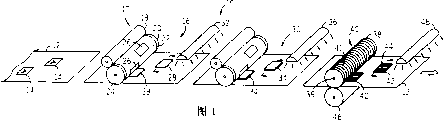
图1是根据本发明选择性成形一个光栅影像的过程的示意图的一个方案。BRIEF DESCRIPTION OF THE DRAWINGS Figure 1 is one version of a schematic diagram of the process of selectively shaping a raster image in accordance with the present invention.
图2是本发明一个实施例的流程图。Figure 2 is a flowchart of an embodiment of the present invention.
图3a是根据本发明的一个方案,平版的涂层材料从一个涂层源单元到一个具有选择性定位的涂层转印区域的涂层敷料器的转印示意图。Figure 3a is a schematic illustration of the transfer of lithographic coating material from a coating source unit to a coating applicator with selectively positioned coating transfer regions according to an aspect of the present invention.
图3b是根据本发明的一个方案,橡皮凸版涂敷层材料从一个涂层源单元到一个具有选择性定位的涂层转印区域的涂层敷料器的转印示意图。Figure 3b is a schematic illustration of the transfer of flexographic coating material from a coating source unit to a coating applicator having selectively positioned coating transfer zones according to one aspect of the present invention.
图3c是根据本发明的一个方案,静电涂敷材料从一个涂层源单元到具有一个选择性定位涂层转印区域的涂层敷料器的转印示意图。Figure 3c is a schematic diagram of the transfer of electrostatic coating material from a coating source unit to a coating applicator having a selectively positioned coating transfer zone, according to an aspect of the present invention.
图3d是根据本发明的一个方案,照相凹板式涂敷材料从一个涂层源单元到一个具有一个选择性定位涂层转印区域的涂层敷料器的转印示意图。Figure 3d is a schematic illustration of the transfer of gravure coating material from a coating source unit to a coating applicator having a selectively positioned coating transfer zone, according to one aspect of the present invention.
图4a是一个局部横断面示意图,显示了采用图3a中所示的涂层敷料器使平版印刷材料从涂层敷料器转印到的衬底的过程。Figure 4a is a schematic partial cross-sectional view showing the transfer of lithographic material from the coating applicator to the substrate using the coating applicator shown in Figure 3a.
图4b是一个局部横断面示意图,显示了采用图3b中所示的涂层敷料器使橡皮凸版材料从涂层敷料器转印衬底的过程。Figure 4b is a schematic partial cross-sectional view showing the transfer of squeegee material from the coating applicator to a substrate using the coating applicator shown in Figure 3b.
图4c是一个局部横断面示意图,显示了采用图3c中所示的涂层敷料器使静电涂敷材料从涂层涂层敷料器转印到衬底的过程;Figure 4c is a partial cross-sectional schematic diagram showing the process of transferring an electrostatic coating material from a coating coating applicator to a substrate using the coating applicator shown in Figure 3c;
图4d是一个局部横断面示意图,显示了采用图3d中所示的涂层敷料器使照相凹板式涂敷材料从涂层敷料器转印到衬底的过程;Figure 4d is a schematic partial cross-sectional view showing the transfer of gravure coating material from the coating applicator to the substrate using the coating applicator shown in Figure 3d;
图5是一个根据图2中方法形成的硬化涂后交错图像局部示意图。图6a是本发明中一个光栅图案形成过程的正视图。FIG. 5 is a partial schematic diagram of an interlaced image after hardcoating formed according to the method in FIG. 2 . Fig. 6a is a front view of a grating pattern forming process in the present invention.
图6b是图6a的局部放大图。Fig. 6b is a partially enlarged view of Fig. 6a.
图7是图5所示的硬化涂后交错图像形成的选择性成形的光栅影像的局部剖视示意图;7 is a schematic partial cross-sectional view of a selectively formed lenticular image formed by the interlaced image after hardcoating shown in FIG. 5;
图8是本发明另一个实施例的流程图;Fig. 8 is a flowchart of another embodiment of the present invention;
图9是根据图8所示的方法形成的硬化涂后交错图像的中间级的局部示意图。9 is a partial schematic illustration of an intermediate stage of a hardcoated interlaced image formed according to the method shown in FIG. 8 .
图10是根据图8所示的方法形成的硬化涂后交错图像的局部示意图;Fig. 10 is a partial schematic diagram of an interlaced image formed according to the method shown in Fig. 8 after hardening coating;
图11是根据图10中的硬化涂后交错图像形成的选择性成形的光栅影像的局部剖视示意图。11 is a schematic partial cross-sectional view of a selectively shaped lenticular image formed from the hardcoated interlaced image of FIG. 10 .
图12是根据本发明的一个方面应用选择性定位的光栅影像技术的一个示例性的终端产品200的示意图;FIG. 12 is a schematic diagram of an exemplary end product 200 employing selectively positioned raster imaging techniques according to an aspect of the present invention;
图13是另一个实施例中的光栅图案形成设备的透视图;13 is a perspective view of a grating pattern forming apparatus in another embodiment;
图14是根据本发明另一个方面中用另外一种方法来选择性成形一个光栅影像示意图;Fig. 14 is a schematic diagram of selectively shaping a raster image with another method according to another aspect of the present invention;
图15a和图15b是光栅图案形成操作的放大的示意图;15a and 15b are enlarged schematic views of the grating pattern forming operation;
图16是本发明另一个方面选择性成形一个光栅影像的另一种方法的示意图。Figure 16 is a schematic illustration of another method of selectively shaping a raster image according to another aspect of the invention.
具体实施方式Detailed ways
参照图1,根据本发明的一个方面描述了一个选择性成形光栅影像的过程。该选择性光栅影像形成系统用数字10所示。系统10中包括印刷有交错图像部分14的衬底12。Referring to FIG. 1, a process for selectively shaping a raster image is depicted in accordance with one aspect of the present invention. The selective lenticular image forming system is shown generally at 10 . Included in the
在衬底上可以有许多任意排列的图像部分14,该图像部分14的尺寸也可以为任意大小、形状或者构造,其覆盖范围可以从一小块到整个衬底12,也可以在衬底的任意部分。作为穿过系统10的单张给进板,图中的衬底12表现为一个薄片状,但实际上衬底12也可以是一部分卷筒(web roll),且该卷片采用现有技术的方式送入系统10。There can be
衬底12通常是纸,但也可以使用其它材料如塑料、金属、合成纸、玻璃或者木头作为衬底。通常,系统10可以被应用在初始印刷时作为工序(现场)的一部分或者应用在需要选择性成形立体效果的预先印刷的材料中,这是系统10的输入部分。图像部分14是,在涂敷适当的光栅片后,通过合适的光栅片观察,可以产生立体效果的图像(也就是光栅影像)。尽管没有特别地表示出来,但依然可以预期到其它的影像也可以是衬底12的一部分,这些影像可以是非光栅图形、印刷文本、条形码、数码照片或者其它合适的图像。衬底以片或薄板的形式被转印到第一次涂敷和硬化步骤16。在步骤16中,一个涂层敷料器17包括一个涂敷单元18和滚板机(plateroller)20。涂敷单元18通常表现为一个圆筒(如一个量筒)。涂敷单元18为滚板机“涂敷”或“上漆”。举例来说,涂层敷料器除了别的形式以外,可以是阿纳洛斯筛(Analox screen)或回转筛的形式。
在这里使用“涂敷”,“上漆”和“光栅涂层”是用来描述覆盖在衬底的交错图像上的材料。该涂层材料在硬化时必须是透明的,最好是无色的。硬化后的涂层也必须有足够的硬度和韧性以便经受得住随后的画面材料处理过程和最终的应用。此外,涂层在液体状态时必须要相对于衬底有足够的粘附性,同时该涂层还应有合适的粘度和表面张力使其在特殊的涂敷过程中按照要求延展或者不延展。该涂层的另一个特点是在连续的操作中能够快速硬化,以便在后续的处理之前,使涂层部分硬化来形成和维持后面全部硬化后的透镜外形。见参考文献中的US 6,551,683,该连续硬化操作被用在别的技术中。As used herein, "coating", "varnishing" and "lenticular coating" are used to describe the material that overlays the interlaced image on the substrate. The coating material must be transparent and preferably colorless when hardened. The hardened coating must also have sufficient hardness and toughness to withstand subsequent graphic material processing and final application. In addition, the coating must have sufficient adhesion to the substrate in the liquid state, and at the same time, the coating should have suitable viscosity and surface tension so that it can be stretched or not stretched as required during the special coating process. Another feature of the coating is its ability to harden rapidly in successive operations, allowing the coating to be partially hardened to form and maintain the later fully hardened lens shape prior to subsequent processing. See US 6,551,683 in references, this continuous hardening operation is used among other techniques.
在一个实施例中,使用的涂层是一种液体聚合物或液体树脂材料,当被涂层敷料器涂敷时,涂层的构成材料处于液体状态(例如,熔融态)。涂层可以按照需要被分层、硬化、形成,与底图相接合,让人在合适的距离上透过涂层可以看到令人满意的商业上的多维光学或者视觉效果。涂层可以包括单一的材料也可以包括多种材料或组合材料。可用材料包括但不限于热塑性塑料,如:聚酯,乙烯基化合物,聚碳酸脂,聚氯乙烯(“PVC”),对苯二甲酸乙二醇酯(“PETG”),无定型聚对苯二甲酸乙二醇脂(“APET”),聚对苯二甲酸乙二醇脂(“PET”),聚苯醚,聚酰氨或尼龙,聚苯乙烯或其它合适的材料。在一个实施例中,凡立水中除了溶剂通常还包括油或树脂。反应型树脂如丙烯酸树脂和甲基丙酸烯树脂,环氧树脂,聚酯树脂,聚氨脂,虫漆也是本发明的较佳选择。In one embodiment, the coating used is a liquid polymer or liquid resin material, the constituent material of which is in a liquid state (eg, molten state) when applied by the coating applicator. Coatings can be layered, hardened, formed as desired, and bonded to the underlying image to allow commercially pleasing multi-dimensional optical or visual effects to be seen through the coating at appropriate distances. Coatings can include a single material or multiple materials or combinations of materials. Available materials include, but are not limited to, thermoplastics such as: polyester, vinyl, polycarbonate, polyvinyl chloride (“PVC”), polyethylene terephthalate (“PETG”), amorphous poly-t-phthalate Ethylene diformate ("APET"), polyethylene terephthalate ("PET"), polyphenylene ether, polyamide or nylon, polystyrene or other suitable material. In one embodiment, the varnish typically includes an oil or resin in addition to the solvent. Reactive resins such as acrylic and methacrylic resins, epoxy resins, polyester resins, polyurethanes, and shellac are also preferred in the present invention.
环氧材料是热固(性)聚合物,也就是说当加热的时候它们会交联(“硬化”)。聚酰亚胺材料通常被用作聚酰胺酸的液态前驱物。经过高温硬化步骤(例如150摄氏度下30分钟和300摄氏度下60分钟),聚酰胺酸发生化学变化(亚胺化反应),变成了固态的聚酰亚胺树脂。Epoxy materials are thermoset polymers, which means they crosslink (“harden”) when heated. Polyimide materials are generally used as liquid precursors for polyamic acid. After a high-temperature hardening step (such as 30 minutes at 150 degrees Celsius and 60 minutes at 300 degrees Celsius), the polyamic acid undergoes a chemical change (imidization reaction) and becomes a solid polyimide resin.
液态的涂层可以是可光硬化或可热硬化的,或者二者都可以。同样地,该液体涂层可以另外包括硬化剂如光引发剂和热引发剂。业内熟知的合适的光硬化剂包括氧化磷化合物和过氟化二苯基钛烯(perfluorinated diphenyl titanocene)化合物。合适的热硬化剂通常为自由基引发剂包括过氧化物,如丁基过辛酸盐(butylperoctoates)和过氧化二异丙苯以及偶氮化合物。当涂层暴露在紫外线光电射线或热(如红外线)下面时,光引发剂被激发与液态涂层反应在表面形成一层硬膜。The liquid coating can be photohardenable or thermally hardenable, or both. Likewise, the liquid coating may additionally include hardeners such as photoinitiators and thermal initiators. Suitable photohardeners well known in the art include phosphorus oxide compounds and perfluorinated diphenyl titanocene compounds. Suitable thermal hardeners are typically free radical initiators including peroxides such as butylperoctoates and dicumyl peroxide and azo compounds. When the coating is exposed to ultraviolet photoelectric rays or heat (such as infrared), the photoinitiator is excited to react with the liquid coating to form a hard film on the surface.
仍然参照图1,滚板机20包括一块印板22,它在辊筒24的周围或者固定在于其上。涂层敷料器17和本例中的滚板机20包括有与交错图像14的形状和尺寸相符合的选择性定位涂层转印区域26。在一个较佳实施例中,印板22被移除并且它还可以被其它具有不同排列的选择性定位涂层转印区域的板所代替。在这样的排列下,一个和另一个之间的差异,或者一个项目与另一个项目之间的差异,可以简单地通过制造新的印板(与换一块新的辊筒相对应)来实现,只要新印板上的选择性定位涂层转印区域与新的或已改变的需要立体效果的交错图像部分相吻合。在实践中,涂层材料通常是液态的。Still referring to FIG. 1 , the rolling
印板22包括选择性定位涂层转印区域26,该区域会被用到下面的涂层转印过程中:平版印刷(或者“胶印”),橡皮凸版印刷或活版印刷(也就是,包括本身是凸起的部分),静电印刷(也就是,包括被充电或放电的部分)和照相凹版印刷(也就是,包括一部分凹陷,坑,“凹穴”),以实现在涂层敷料器17和衬底12之间的涂层转印。
这里用的“吻合”是用来表示在选择性定位涂层转印区域,衬底上的交错图像部分以及涂层材料本身之间的联系。特别地,选择性定位涂层转印区域与交错图像部分相“吻合”,在尺寸、形状上都相互匹配,相同或一致。此外,该选择性定位涂层转印区域被用来直接或间接地(例如,通过胶印过程)转印涂层材料来覆盖或实质上覆盖交错图像部分。由于该材料在尺寸和形状上与交错图像部分相匹配,相同或一致,因此,涂层本身最终与交错图像相吻合或者实质上吻合。As used herein, "coincidence" is used to denote the relationship between selectively positioned coating transfer regions, interlaced image portions on the substrate, and the coating material itself. In particular, the selectively positionable coating transfer areas "mesh" with the interlaced image portions, matching each other in size, shape, identical or identical. Additionally, the selectively positioned coating transfer region is used to directly or indirectly (eg, via an offset printing process) transfer coating material to cover or substantially cover the interlaced image portions. Since the material matches, is identical or identical to the interlaced image portion in size and shape, the coating itself eventually conforms or substantially conforms to the interlaced image.
涂后的交错图像28接下来被硬化单元32所硬化。硬化过程直到涂层达到了预先设定的硬化程度后结束。硬化程度的确定可以依据多个变量,但是在一个较佳实施例中根据涂层的硬度和张力,其可以适合于:a)利用图案形成设备形成并维持光栅图案的形状,外形和/或样式;或者b)形成另一个或后续的涂层,并把后层和前层结合在一起。前者可以被称为“光栅图案确定硬化程度”,后者可以被称为“涂层涂敷硬化程度”。硬化程度由许多因素决定,包括但不限于:涂层材料类型(下面描述),材料温度,操作环境温和湿度,图案形成设备使用的压力,或者可选的,后续的涂层。在设置或确定一个初始或后续的硬化程度时这些因素都被考虑进去。The painted interlaced
硬化可以采用任何可接受的形式,在较佳实施例中包括紫外线(UV)和电子束(EB)硬化技术。在一个实施例中,进行了单一的涂敷和硬化操作16。在本发明其它的实施例中,可以采用另外的涂敷和硬化操作,采用如图所示的第二涂敷和硬化操作30,在涂敷后(且初步硬化后)的交错图像28上再次进行涂敷,以产生具备所需涂敷深度的已硬化涂后交错图像34(cured coated interlacedimage)。已硬化涂后交错图像34然后被硬化单元36所硬化(在没有其它的涂敷和硬化操作且已达到所需的涂敷深度的情况下,这就是最后的硬化操作)。另外,如果进行了多重的涂敷和硬化操作,将会产生“中间级”的涂后交错图像。Hardening may take any acceptable form, including in preferred embodiments ultraviolet (UV) and electron beam (EB) hardening techniques. In one embodiment, a single coating and hardening
可以预期到,有可能需要更多的涂敷和硬化操作。通过把同一张薄片送入相同的设备多次,操作16和30可以由相同的机构来执行,或也可以通过不同位置上的机构来执行,例如,位于流水线上不同位置的单元,一个操作接着前一个操作的结果。It is contemplated that more coating and hardening operations may be required.
涂后交错图像28上涂层的厚度会根据衬底12的特殊使用需要而不同,为在印好的交错图像部分14上达到所需的涂敷程度,可能会需要更多的涂敷和硬化操作。所需的涂敷程度要根据所需的立体效果来决定,如需要的深度,间距,滚距,焦距以及其它类似的由使用效果和需求所决定的因素。示例的透镜间距和相应的滚距包括:每英寸100行或透镜数(参照”每英寸行数”或“透镜数”),滚距为14密耳(mil);每英寸200行对应的滚距为6密耳,每英寸300行对应的滚距为5密耳,等等。The thickness of the coating on the interlaced
一旦光栅材料的所需厚度被确定且被硬化到了预设的硬化程度,就产生了已硬化涂后交错图像34,图像34通过一个光栅图案形成设备38被转印。在一个较佳实施例中,光栅图案形成设备38是一个具有图案40的压花辊筒。选择性成形光栅影像42包括多个透镜(如,一个光栅图案)44,它们是使用辊筒图案40产生的。换句话说,使用图案40来确定已硬化涂后交错图像34上所需的分辨率或每英寸行数(LPI)。图案40包括多个槽41,这些槽通常平行或同心于光栅图案形成设备38的中轴线39。通过转动光栅图案形成设备38,图案40被转印到已硬化涂后交错图像34上,建立起一个选择性成形光栅影像42。选择性成形光栅影像42中含有透镜44。光栅图案形成设备38的放置要与压紧辊46和衬底12相配合,以使图案40压进已硬化涂后交错图像34。形成过程只发生在已硬化涂后交错图像34上从而产生选择性成形光栅影像42。换句话说,图案40不会在衬底12的其它部分上形成。另外,可以通过设置图案40的深度来获得更高级的效果。图案40的理想深度是能建立一个大约为透镜(包括一层或多层的涂层)滚距三分之一的光栅图案。不考虑深度的话,在选择性成形光栅影像42中就形成了实质上统一的图案。较佳的是,通过给已硬化涂后交错图像34压花来产生选择性成形光栅影像。结果是,压花出现在已印有光栅影像的衬底12的相同位置上。Once the desired thickness of the lenticular material is determined and hardened to a predetermined level of hardening, a hardened interlaced
如果需要适当的处理(如,凝固和强化)最终的光栅影像并进行必要的透镜收尾工作,可以进行后续的压花处理或者在选择性成形光栅影像42中形成其它形式的光栅图案40,以及附加的硬化操作48。Subsequent embossing or other forms of
图2是流程50所示的、生产图1所示的选择性成形的光栅影像42实施例的流程图。流程50描述了单一的涂敷-硬化操作(不考虑最终的硬化),但是应该看到本发明可以根据需要包括更多或更少的涂敷-硬化操作。图像部分的印刷过程52是必要的预处理步骤,其包括:交错图像9详细位置的选择,及其数量,尺寸和形状的确定,以及非透镜信息,文本或者图形的印刷位置的确定。该交错图像可以包括组成颜色,例如,青色,品红色,黄色和黑色(“CMYK”),红,绿,兰(“RGB”),或者只能在特定光线如紫外线下才可见的“无色的”墨水。交错图像可以用多种技术印刷,包括平版印刷,橡皮凸版印刷,凹版印刷,照相凹版印刷,铅印,激光,喷墨,丝网,数字,单张(sheet-fed)印刷,和卷筒(web)印刷等等。其它的信息可以被印刷在衬底上,如非交错图像,文本,图形,图片并且该衬底同时还可以包括空白和“非印刷”区域。FIG. 2 is a flowchart, shown as process 50 , for producing an embodiment of the selectively shaped
接下来,在步骤54中涂敷第一层涂料。更加明确地,如图3a-3d所示,涂层材料56可以涂敷在衬底58的预先选好的交错图像上(也就是,至少有一处印在衬底上的交错图像的部分)。可以使用一个涂层敷料器17来完成涂敷的工作。涂层敷料器17包括一个具有印板64的印板滚筒62,该印板(例如,平版,橡皮凸板,静电板或者照相凹板)具有选择性定位的涂层转印区域66a-d。Next, in step 54 a first coat of paint is applied. More specifically, as shown in FIGS. 3a-3d, the
如图3a和4a中所示,在一个实施例中,涂层材料56(如塑料,凡立水,或者其它的透镜材料)通过选择性定位的涂层转印区域66a以平版印刷的形式转印到衬底58,以使涂层仅转印到衬底58的交错图像部分57上。无论通过胶印还是其它形式,平版转印可以包括有化学斥力或者涂层材料和涂层转印区域之间的斥力。在此实施例中,涂层敷料器包括计量辊59,形成辊61,滚板机20和前辊筒63。计量辊59旋转,从容器74中取得些涂层材料56(它在此时通常为液态)并把这些涂层材料转印给形成辊61。形成辊然后把涂层材料平版转印给滚板机20,特别地,该材料被转印给选择性定位的区域66a。最后,涂层材料56被转印到衬底58上的交错图像57上,在这里间接的用到了前辊筒63。加压辊65可以被应用来产生足够的夹力或压力以使涂层材料56被正确地转印到衬底58。在此实施例中,选择性定位的涂层转印区域66a可能被印板64的表面对齐。为完成涂层材料的转印,所示的这些辊筒按箭头所示方向旋转,衬底按箭头所示方向移动。As shown in FIGS. 3a and 4a, in one embodiment, the coating material 56 (such as plastic, varnish, or other lens material) is transferred lithographically by selectively positioned
请参阅图3b和4b,在本发明的另一个实施例中,涂层材料56被平版化地转印到衬底58,这里通过选择性定位的涂层转印区域66b以使涂层仅转印到衬底58的交错图像57上。在此实施例中,制造选择性定位的涂层转印区域66b作为与涂层材料56相接触的凸起部分以使涂层仅转印到衬底58的交错图像57上。在操作过程中,涂层敷料器17包括相对计量辊59转动的滚板机20。计量辊59从图中的收集区域或溶液槽中取得一些涂层材料56。涂层材料56被计量辊59所获取,并通过物理接触转印到选择性定位的涂层转印区域66b,此区域在滚板机20的印板64上,随后涂层材料被转印到衬底58的交错图像部分57。可以利用设备76(如刮刀或刮墨刀)以确保从涂层敷料器转印刀衬底的涂层具有适当厚度(无论相同还是不同)且均匀光滑,更特别地,在此实施例中,是从计量辊到滚板机。一个加压辊65可以被应用来产生足够的夹力或压力以使涂层材料56正确的转印到衬底58。为完成涂层材料的转印,所示的这些辊筒和衬底可以按箭头所示方向旋转或移动。在一个实施例中,涂层敷料器60可以包括开槽或者槽状冲模,其用来制造旗帜,连续的面板以及缎带。Referring to Figures 3b and 4b, in another embodiment of the present invention, the
请参阅图3c和4c,在本发明的另一个实施例中,涂层材料56被静电转印到衬底58,这里通过选择性定位的涂层转印区域66c以使涂层仅转印到衬底58的交错图像57上。在此实施例中,选择性定位的涂层转印区域66c被充电(例如,图中所示为正电荷)以粘上或吸附一些带相反电荷的涂层材料56。在操作过程中,涂层敷料器17包括相对计量辊59转动的滚板机20。计量辊59从图中的收集区域或溶液槽中取得一些涂层材料56。涂层材料56被计量辊59所获取,并通过静电转印到选择性定位的涂层转印区域66c,此区域在滚板机20的印板64上,随后涂层材料被转印到衬底58上的交错图像区57。可以利用设备76(如刮刀或刮墨刀)以确保从涂层敷料器转印刀衬底的涂层具有适当厚度(相同或不同)且均匀光滑,更明确地,在此实施例中为从计量辊到滚板机。一个加压辊65可以被应用来产生足够的夹力或压力以使涂层材料56正确的转印到衬底58,也就是说,可以产生足够的压力来克服上面的提到的静电(也称为“电”或“电荷”)吸附。转印过程也可以利用涂层和具有交错图像的衬底之间的电吸附或电荷吸附(单独起作用或与辊隙间的压力相配合)来实现。为完成涂层材料的转印,所示的这些辊筒按箭头所示方向旋转,衬底可以按箭头所示方向移动。在另一可选实施例中,涂层的静电转印可以通过与图3a和图4a所描述的相类似的“胶印(offset)”或“间接(indirect)”的机械布置来完成。3c and 4c, in another embodiment of the present invention, the
在图3d和4d本发明的另一个实施例中,涂层材料通过凹版印刷或照相凹版布置被转印到衬底58,这里通过选择性定位的涂层转印区域66d以使涂层仅转印到衬底58的交错图像57上。在这个实施例中,选择性定位的涂层转印区域66d上形成一些凹穴以收集涂层材料56。在操作过程中,涂层敷料器17包括相对计量辊59转动的滚板机20。计量辊59从图中的收集区域或溶液槽74中取得一些涂层材料56。涂层材料56被计量辊59所获取,被转印到选择性定位的涂层转印区域66c,此区域凹陷在滚板机20的印板64上,随后涂层材料被转印到衬底58上的交错图像区57。第一设备76(如刮刀或刮墨刀)以确保从涂层敷料器转印刀衬底的涂层具有适当厚度(无论相同或不同)且均匀光滑,更特别地,在此实施例中是从计量辊到滚板机。可以使用第二设备77(例如一个刮墨刀)来整平在凹陷的选择性定位涂层转印区域66d内的涂层材料56。一个加压辊65可以被应用来产生足够的夹力或压力以使涂层材料56正确的转印到衬底58。为完成涂层材料的转印,所示的这些辊筒按箭头所示方向旋转,衬底可以按箭头所示方向移动。In another embodiment of the invention in Figures 3d and 4d, the coating material is transferred to the
图3a-d和图4a-d是为了方便理解本发明而提供的示意图。本领域内的技术人员可以按需求采用其它类型的辊筒,装置和机械组件(如,具有多个辊筒的辊筒式输送机)。Figures 3a-d and Figures 4a-d are schematic diagrams provided for the convenience of understanding the present invention. Those skilled in the art can use other types of rollers, devices and mechanical components (eg, roller conveyors with multiple rollers) as desired.
图5描述了一个涂后交错图像80,它是上面的图2,图3a-b,图4a-b中所阐述的涂敷步骤54的产物。一个典型的涂后交错图像包括交错图像区82和在选择性地定位于交错图像区上的涂料层84,图像部分和涂层都在衬底86上。此方法可以包括使已硬化交错图像与光栅图案形成设备相接触以及控制光栅图案形成设备的温度,使已硬化涂后交错图像从光栅图案形成设备上分离。Figure 5 depicts a post-coating
请参阅图2,在涂敷步骤之后,是涂后交错图像的硬化步骤55。在硬化之后的涂后交错图像80(图5)在这里被称为已硬化涂后交错图像。在较佳实施例中,所述的硬化可以为紫外线(UV)硬化,电子束(EB)硬化,以及热固着硬化技术。硬化技术已为业内熟知,其可以使被硬化材料具有合适的强度,弹性,刚度,硬度等等。通常,在达到了预定的硬化程度后硬化步骤结束。Referring to Fig. 2, after the coating step, there is a post-coating interlaced image hardening step 55. The painted interlaced image 80 (FIG. 5) after hardening is referred to herein as a hardened painted interlaced image. In a preferred embodiment, the curing may be ultraviolet (UV) curing, electron beam (EB) curing, and heat set curing techniques. Hardening technology is well known in the industry, which can make the material to be hardened have proper strength, elasticity, rigidity, hardness and so on. Typically, the hardening step ends after a predetermined degree of hardening has been reached.
接下来,在硬化步骤之后,已硬化的涂后交错图像被形成57在一个选择性成形的光栅影像内。在本发明的一个较佳实施例中,已硬化涂后交错图像在光栅图案形成过程中被压花。最终的硬化步骤58可以包括所需的形成步骤57。Next, after the hardening step, the hardened coated interlaced image is formed 57 within a selectively shaped lenticular image. In a preferred embodiment of the invention, the interlaced image is embossed during the formation of the lenticular pattern after the hardcoat. A
参见图6a-b,为本发明一方面的光栅图案形成操作的正视图和该操作的放大视图。如图所示,有两个光栅图案形成设备的实施例88a-b。在实施例88a中的图案形成设备包括许多与图案形成设备的中轴线92同心的开槽90。较佳的采用压花方式,开槽90用于在涂层96上形成光栅图案94,涂层根据衬底100上的交错图像98被选择性定位。压紧辊102在压花过程中承载涂层和具有交错图像的衬底。在另外一个实施例中,图案形成设备88b包括许多与设备106的中轴线106平行的开槽。更好的是,光栅图案形成设备具有实质覆盖全部设备拱面的开槽图案。在本文参考文献的10/340,075号美国专利申请中详细描述了本发明所使用的一个图案形成设备。See Figures 6a-b, which are front views and enlarged views of a grating patterning operation of an aspect of the present invention. As shown, there are two
图7是一个局部剖视示意图,描述了由图5中的已硬化涂后交错图像而来的选择性成形的光栅影像108。选择性成形的光栅影像108包括交错图像区82和选择性定位在交错图像区的具有多个微透镜112的光栅片110,图像部分和光栅片位于衬底86上面。光栅片110具有一定的滚距,使观察者在一定的角度内(也就是,采用适当的多维处理以使图像在正确的焦距上)在合适的距离上透过透镜可以看到交错图像。光栅片110的滚距“G”与镜片的厚度有关,镜片厚度指的是从微透镜112的顶部到透镜材料(也就是,具有交错图像82的透镜的后平面)底部的这段距离。在一个较佳实施例中,光栅片的滚距“G”等于它自己的焦距。微透镜112的形成深度“D”是指从微透镜112的顶面到两个透镜的交点的这段距离。在一个较佳实施例中,可以使用一个滚距小于10密耳(mil)的透镜。在另一个较佳实施例中,所需的形成深度范围在滚距的5%到30%之间。例如,对于一个滚距为6密耳的透镜来说,形成深度将大概是2.0密耳。在任何情况下,形成的一个目的就是能够把图案(如在图案形成设备中的雕刻图案)完全再现。通常,滚距D和形成深度D的选择要基于多种因素,包括交错图像和观察者的观看距离,以获取最好的光学透明度和多维效果的品质。FIG. 7 is a schematic partial cross-sectional view illustrating the selectively formed
适当的选择性成形的光栅影像108可将图像衰减降到最低。图像衰减可以有多种形式,比如包括模糊和/或重影。通常,观察者将会从需要或预定的距离观察光栅影像。如想得理想的效果(如运动和/或深度),观察者在观察光栅影像时将会变换观察的角度。可以通过移动光栅影像本身(如杯子或收藏卡上的手持图像)来代替观察者从一个方位移动到另外一个方位,或者把两者结合起来。另外,前驱图像(结合在透镜上来产生光栅影像)是两个或多个图像组件的合成。当观察者的角度变化时,通常就可以看到一个或多个图像组件。其余的图像组件在该角度下将不会显示出来。当不应该被观察者看到的图像组件显示出来时,就发生“鬼影”现象。Proper selectively shaped
图8是本发明另一个实施例流程图。在此实施例中,描述了多个,特别地是两个硬化-涂敷操作(也叫做双硬化-涂敷操作)。当最终产品或在使用中需要涂层的叠加以获得具有理想滚距的透镜时就需要双硬化-涂敷操作。交错图像区的印刷步骤152,是生产选择性成形的光栅影像的必要的预处理步骤。接下来,涂敷第一层涂料154。涂层的涂敷可以根据上面图2描述的过程完成。Fig. 8 is a flowchart of another embodiment of the present invention. In this embodiment, multiple, in particular two curing-coating operations (also called double curing-coating operations) are described. A double cure-coat operation is required when the final product or in use requires the superposition of coatings to obtain a lens with the desired roll pitch. The
图9显示了按图8中的方法生成的中间级涂后交错图像180的局部示意图。此中间级图像是涂敷步骤154(图8)的产物。一个典型的中间级涂后交错图像180包括交错图像区182和选择性定位在交错图像区的涂层材料层184,图像部分和涂层在衬底186上。FIG. 9 shows a partial schematic diagram of an interlaced
回到图8,即使非常简要,在涂敷步骤之后,所述的中间级涂层184被步骤155所硬化,在硬化之后,中间级涂后交错图像180(图9)被称为已硬化的中间级涂后交错图像。另外,在较佳实施例中,所述的硬化可以是紫外线(UV)硬化,电子束(EB)硬化,或者热固着硬化技术。第二层涂层材料在步骤157中被涂敷,形式与第一层类似,可以理解的是第二层涂层是涂敷在第一层涂层之上的(与交错图像区相对比)。虽然如此,第二层也与交错图像相吻合。随后,可以进行对第二涂层的硬化159。Returning to FIG. 8, even though very briefly, after the coating step, the
图10是根据图8中的方法形成的已硬化涂后交错图像190的局部示意图。图中所示的已硬化涂后交错图像包括具备交错图像层184的衬底186上的交错图像182以及与交错图像区相一致的第二涂层192,在本例中这是最后的涂层。FIG. 10 is a partial schematic illustration of a hardcoated
还回到图8,在硬化步骤159之后,在步骤160中已硬化涂后交错图像被形成在一选择性成形的光栅影像中。在本发明的一个较佳实施例中,所述的已硬化涂后交错图像的压花发生在光栅图案形成操作中(其方式与图6a-b所示类似)。在160之后可以根据需要包括一个最终的硬化操作162。Fig.11 is a partial schematiccross-sectional view of a selectively formedReturning also to FIG. 8, after hardening
图11是一个选择性成形的光栅影像194的局部剖视示意图,该光栅影像由图10中的已硬化涂后交错图像160形成。光栅影像194包括衬底186上的交错图像区182,光栅片196包括涂层184和涂层192,在涂层192上形成多个的微透镜198。FIG. 11 is a schematic partial cross-sectional view of a selectively formed
图12是一个示例性的最终产品20的示意图,其包括了本发明一方面中的选择性成形的光栅影像202。图中所示的选择性成形的光栅影像构成了全部或充分完全的整张图像,或者选择性的,做为一个大片的印刷区域204的一部分。换句话说,在产品开发阶段,可以选择在区域或者部分区域放置所述的选择性成形的光栅影像。适用的终端产品可以包括:印刷品(如杂志、报纸),广告插页,书籍封面,产品包装,容器,标签,CD或DVD封面或“铭牌(tip-ons)”,杯套,以及购物点展示,等等。另外,终端产品可以是用卷筒或片状物形成技术制成的。FIG. 12 is a schematic illustration of an exemplary
图13是另一个实施例的光栅图案形成设备300的立体图,该设备包括一个具有底面302的平的压盘301(也被称为模糟或心轴)。为方便描述,设备300的朝向是底面可见而顶面隐藏。压盘的顶面可以按需要全部或局部(如热的或可加热的顶面区域)加热(如通过电热或燃料油加热)或冷却。压盘的底面302包括一块凹陷的区域304,在其中可以放许多光栅选择的图案形成冲模306(在这里画了三块冲模)以便使用。所述的凹陷区域也可以是平的部分(图中未示)。每一个冲模306包括一个光栅图案形成表面308(在这里是压花用),该表面上包括许多开槽310,每一个开槽的尺寸和形状都与将由冲模306形成的光栅片的每一个透镜相对应(例如反向)。图中所示的开槽310是抛物线形的,但其它的形状(如椭圆,梯形,三角形,锯齿形,圆形,半圆形等等)也在本发明的范围之内。FIG. 13 is a perspective view of another embodiment of a
压盘301本身的尺寸和形状一般要与衬底或印刷材料相对应。凹陷区域304的深度由压花或形成的材料的尺寸及类型决定。值得注意地,选择性图案形成冲模306可以按需要朝向任何方向,如图所示有多个方向,这样在一个衬底或印刷页上就可以获得多种的多维效果。所述的选择性图案形成冲模306的数量和位置的选择可以基于所创建的光栅影像的数量来完成,尺寸和位置的确定要与选择性定位的交错图像相一致,这些会有详细的描述。确定选择性图案形成冲模的尺寸来形成不同尺寸和/或间距的光栅图案以产生不同宽度和深度的微透镜。使用压盘301定位和形成选择性图案形成冲模306,例如采用电磁体、永久磁体、或者机械附件(例如,可调螺丝)的方式。The size and shape of the platen 301 itself generally corresponds to the substrate or printing material. The depth of the recessed area 304 is determined by the size and type of material that is embossed or formed. Notably, the selective patterning die 306 can be oriented in any direction as desired, as shown in multiple directions, so that a variety of multi-dimensional effects can be achieved on a single substrate or printed page. The selection of the number and location of the selective patterning dies 306 can be done based on the number of raster images created, sized and positioned to correspond to the selectively positioned interlaced images, as will be described in detail. The selective patterning die is sized to form grating patterns of different sizes and/or pitches to produce microlenses of different widths and depths. Platen 301 is used to position and form selective patterning die 306, for example by means of electromagnets, permanent magnets, or mechanical attachments (eg, adjustable screws).
应该注意到,在一个实施例中,冲模尺寸可以为所需的立体效果的最小尺寸,也可以是一个冲模覆盖或填充了所有的凹陷区域,该区域可被用来获得光栅图案,形成的方法与前面图6a-b中使用图案形成设备的方法相类似。这样的实施例如图13b所示。在另一中方法中,在压盘301上具有全部凹陷区域冲模305的光栅图案形成设备300看上去像一个展开的圆柱形光栅图案形成设备。另外,可以预期到压盘尺寸和一个或多个的冲模尺寸可以有多种组合和比例以获得商业上可行的光栅图案形成设备。It should be noted that, in one embodiment, the die size may be the minimum size required for the three-dimensional effect, or one die may cover or fill all the recessed areas that may be used to obtain the grating pattern, the method of forming Similar to the method using the patterning device previously described in Figures 6a-b. Such an embodiment is shown in Figure 13b. In another approach, the
图14是根据本发明的另一方面选择性成形的光栅影像的另外一个方法的示意图。通常,该方法与前面图1-12所描述的方法相承,那些组件都是一样的。需要注意的是,为简洁起见,省略描述硬化操作(无论一次还是多次)。这里的选择性光栅影像形成系统为数字350。系统350包括具有印好的交错图像314的衬底312(见图1及相关说明中衬底以及交错图像的部分)。一个图中所示的涂层敷料器317按前面图1-12中所述的方法选择性的把涂层材料涂敷到衬底312上,更确切的说是涂敷到衬底上的已印刷区域314上。在硬化操作之后,已硬化的涂后交错图像320被形成且该已硬化涂后交错图像被图示的光栅图案形成设备300形成到选择性成形的光栅影像中。14 is a schematic diagram of another method of selectively shaping a lenticular image according to another aspect of the invention. In general, the approach follows that described earlier in Figure 1-12, and those components are the same. It should be noted that, for the sake of brevity, the description of the hardening operation (whether one time or multiple times) is omitted. The selective lenticular image forming system here is the
图15a-b是描述光栅图案形成操作322的放大示意图。参考图13和图15a-b,操控所述的光栅图案形成设备300来定位多个位于压盘底面302上的选择性图案形成冲模306,确切的说,是使有带槽冲模的图案形成表面308与已硬化的涂后交错图像320相接触。衬底312通常按箭头323所示的方向移动。这样,光栅图案被形成(如图所示通过冲压或压花的方式)在已硬化涂后交错图像320的涂层上。值得注意的是,由于冲模的位置与已硬化涂后交错图像320的位置精确一致,形成多个选择性成形的光栅影像324。同样,图中还显示了印刷好的非光栅影像或区域328。光栅图案形成设备300按箭头326所示方向运动完成形成。光栅图案形成设备300能够在适当的压力下形成光栅图案。需要注意的是,尽管图中没有显示,如果有需要,可以进行附加的二次形成或压花操作。15a-b are enlarged schematic diagrams illustrating the
图16是根据本发明的另一个方面选择性成形的光栅影像的另一种方法的示意图。在这里,在衬底403上已印刷交错图像402上选择性涂敷了涂层,以生成一个已硬化涂后交错图像400。如图所示,涂层敷料器404包括一个金属箔辊筒406或薄膜涂层408。该薄膜通常是预先生产的(与前面描述的方法相对应)足够清晰的材料。本发明所采用的一种材料是从英国API Group,PLC获取的光泽钴(CO)10100。16 is a schematic diagram of another method of selectively shaping a raster image according to another aspect of the invention. Here, a coating is selectively applied over a printed interlaced
涂料从转印滚或转印筒406被转印至衬底403,确切的是,被压盘或冲压单元410通过加热(例如通过上述的加热的或可加热的区域)或加压的方法转印到影像区域402上。冲压单元410与前述的单元300类似,而410单元不包括选择性图案形成冲模,但包括平的或足够平的冲模。值得注意的是,由于平的冲模也与印好的交错图像或图像区域402相一致,冲压部分被选择性地转印到衬底以精确地覆盖已印刷的图像区域。剩余的膜412形成图示的废辊414。具有涂后交错图像的衬底按箭头416所示方向运动,以经过前述的一个或多个硬化步骤。已硬化的涂后交错图像400随后被按箭头422所示方向运动的光栅图案形成设备300形成在选择性定位的光栅影像420中(参见图13a-b和15a-b)。在一个实施例中,这个过程会涉及到利用金属箔或膜的热印选择性成形的光栅图案形成过程。The paint is transferred from the transfer roll or
上述方法中的功能可以通过多种物理装置完成。例如,本发明的一个制做选择性成形的光栅图案的系统包括:涂敷装置,对于一个在衬底上印刷的交错图像部分,与交错图像相吻合来形成涂后交错图像的涂层,该装置包括一个与衬底上交错图像相一致的选择性定位的涂层转印区域;硬化涂后交错图像装置,以产生已硬化的涂后交错图像;以及光栅图案形成装置,在已硬化的涂后交错图像上形成光栅图案以产生选择性定位的光栅影像。The functions in the above methods can be performed by various physical means. For example, a system for making a selectively formed lenticular pattern of the present invention includes coating means, for a printed interlaced image portion on a substrate, conforming to the interlaced image to form a coated interlaced image coating, the The apparatus includes a selectively positioned coating transfer region in conformity with the interlaced image on the substrate; hardened post-coated interlaced image means for producing a hardened post-coated interlaced image; A raster pattern is formed on the post-interlaced image to produce a selectively positioned raster image.
在某些应用中可能需要在衬底的两面都产生选择性定位的光栅影像(无论示以薄片还是卷筒的形式)。在本发明中可以使用双面印刷机把衬底进行旋转以得到双面光栅的产品。在这种方法中,可以实现一个或多个涂层到衬底两个表面上的选择性成形的光栅影像的转印。In some applications it may be desirable to produce selectively positioned lenticular images on both sides of the substrate (whether shown in sheet or roll form). In the present invention, a double-sided printing machine can be used to rotate the substrate to obtain a double-sided lenticular product. In this method, the transfer of a selectively shaped lenticular image of one or more coatings onto both surfaces of a substrate can be achieved.
大体上,已经按顺序形式阐述完了相关的方法。对这些方法的修改,重新整理,组合,再安排体现在后面的权利要求中。本发明提出了在涂层上形成(如压花)光栅图案的系统和方法,且该形成不依赖于涂层在衬底已印交错图像上的定位。同样的图案形成设备(如槽压花辊筒)可以很方便地从从一个印刷作业应用到下一个作业(或者与甚至在同一个作业中都位置不同的涂后交错图像一起)。换句话说,由光栅图案形成设备完成的形成独立于衬底上交错图像位置,尺寸,形状的变化,因为一个图案形成设备可以应对这些变化。In general, the related methods have been explained in sequential form. Modifications, rearrangements, combinations, and rearrangements of these methods are embodied in the following claims. The present invention presents systems and methods for forming (eg, embossing) a grating pattern on a coating that is independent of the positioning of the coating on a printed interlaced image on a substrate. The same patterning device (such as a grooved embossing cylinder) can be easily applied from one print job to the next (or with post-coated interlaced images that are positioned differently even within the same job). In other words, the formation accomplished by the lenticular patterning device is independent of variations in the position, size, and shape of the interlaced images on the substrate because one patterning device can handle these variations.
已经通过不同的实施例对本发明进行了描述。除了那些明确表述的方面以外的类似的方面和改动都属于下面权利要求的范畴。The invention has been described through different embodiments. Similar aspects and modifications in addition to those expressly stated are within the scope of the following claims.
Claims (87)
Applications Claiming Priority (2)
| Application Number | Priority Date | Filing Date | Title |
|---|---|---|---|
| US46282103P | 2003-04-14 | 2003-04-14 | |
| US60/462,821 | 2003-04-14 |
Publications (1)
| Publication Number | Publication Date |
|---|---|
| CN1805906A true CN1805906A (en) | 2006-07-19 |
Family
ID=33299995
Family Applications (1)
| Application Number | Title | Priority Date | Filing Date |
|---|---|---|---|
| CNA2004800166497A Pending CN1805906A (en) | 2003-04-14 | 2004-04-14 | Lenticular images formed on selected images portions |
Country Status (5)
| Country | Link |
|---|---|
| US (1) | US20040219302A1 (en) |
| EP (1) | EP1613558A2 (en) |
| CN (1) | CN1805906A (en) |
| CA (1) | CA2522218A1 (en) |
| WO (1) | WO2004092085A2 (en) |
Cited By (6)
| Publication number | Priority date | Publication date | Assignee | Title |
|---|---|---|---|---|
| CN102472995A (en) * | 2009-07-15 | 2012-05-23 | 曼·胡默尔有限公司 | Method and device for marking objects, particularly components of a motor vehicle, with an embossed hologram and objects marked in this way |
| CN102798912A (en) * | 2012-07-20 | 2012-11-28 | 李红军 | Membrane material grating prepared by APET advanced material |
| CN107234871A (en) * | 2016-03-28 | 2017-10-10 | 丰田科技股份有限公司 | Grating plate printing machine and method thereof |
| CN109823030A (en) * | 2018-12-30 | 2019-05-31 | 深圳博华仕科技有限公司 | A kind of micro-fluidic chip print makes system and print makes method |
| CN110831773A (en) * | 2017-07-05 | 2020-02-21 | 宝洁公司 | Method for printing 3D micro-optical images on packaging systems |
| CN115302958A (en) * | 2022-08-31 | 2022-11-08 | 赛维精密科技(广东)有限公司 | Method and equipment for manufacturing printing, code spraying and back printing integrated label |
Families Citing this family (22)
| Publication number | Priority date | Publication date | Assignee | Title |
|---|---|---|---|---|
| BE1014861A6 (en) * | 2002-05-31 | 2004-05-04 | Techni Coat International Nv | Method and apparatus for printing |
| US7712673B2 (en) * | 2002-12-18 | 2010-05-11 | L-L Secure Credentialing, Inc. | Identification document with three dimensional image of bearer |
| US20050150964A1 (en) * | 2004-01-14 | 2005-07-14 | Lo Allen K. | Counterfeit proof label having optically-concealed cross reference color codes and apparatus for making same |
| JP4684647B2 (en) * | 2004-12-28 | 2011-05-18 | グラパックジャパン株式会社 | Pattern forming method and pattern forming apparatus |
| US20060213610A1 (en) * | 2005-03-24 | 2006-09-28 | Mcdonnell Ryan | Method and apparatus for applying a cast finish to a printed substrate |
| CN1710448A (en) * | 2005-06-09 | 2005-12-21 | 吴德明 | Grating lens made by printing and coating and production technology |
| GB0513475D0 (en) * | 2005-07-01 | 2005-08-10 | Facestation Ltd | An imaging system |
| CA2630156A1 (en) * | 2005-11-16 | 2007-05-24 | Meadwestvaco Packaging Systems Llc | Paperboard for use in water resistant packaging |
| KR20080015536A (en) * | 2006-08-16 | 2008-02-20 | 삼성전자주식회사 | Wire Grid Polarizer Manufacturing System and Manufacturing Method |
| DE102006045640A1 (en) * | 2006-09-27 | 2008-04-03 | Ccl Label Gmbh | Arrangement and method for producing a lenticular film web and in particular a lenticular label web |
| EP2055479A2 (en) | 2007-10-30 | 2009-05-06 | manroland AG | Transfer printing procedure |
| JP5214311B2 (en) * | 2008-04-15 | 2013-06-19 | リンテック株式会社 | Method for manufacturing scattering prevention film |
| JP5471916B2 (en) * | 2010-07-12 | 2014-04-16 | 株式会社リコー | Image forming apparatus |
| DE102011012308B4 (en) * | 2011-02-25 | 2015-10-15 | Franz Huber | Method for producing a structure device with topographic relief |
| KR102156013B1 (en) * | 2013-03-28 | 2020-09-15 | 미쯔비시 케미컬 주식회사 | Optical film production method, optical film, surface light-emitting body and optical film production device |
| PL229060B1 (en) | 2013-12-02 | 2018-06-29 | Axxel Spolka Z Ograniczona Odpowiedzialnoscia | Multilayer printing laminate |
| TWI491925B (en) * | 2013-12-06 | 2015-07-11 | Zhangjiagang Kangde Xin Optronics Material Co Ltd | A super stereoscopic vision separation element |
| GB201512118D0 (en) | 2015-07-10 | 2015-08-19 | Rue De Int Ltd | Methods of manufacturing security documents and security devices |
| US10377095B2 (en) | 2015-08-20 | 2019-08-13 | Hp Indigo B.V. | Printed facets |
| US20170075125A1 (en) * | 2015-09-11 | 2017-03-16 | Hyundai Motor Company | Radio-wave transparent cover for vehicle |
| US20170123112A1 (en) * | 2015-10-28 | 2017-05-04 | Joel Scott Scarbrough | Multilayered Press Stable Lens Array Film |
| EP3424739A1 (en) * | 2017-07-05 | 2019-01-09 | The Procter & Gamble Company | Method of printing 3d-microoptic images on packaging systems |
Family Cites Families (47)
| Publication number | Priority date | Publication date | Assignee | Title |
|---|---|---|---|---|
| US4406189A (en) * | 1977-05-25 | 1983-09-27 | Neefe Charles W | Method of making lenses with a lenticular cut |
| US4414316A (en) * | 1980-09-05 | 1983-11-08 | Rexham Corporation | Composite lenticular screen sheet |
| US4420502A (en) * | 1980-09-05 | 1983-12-13 | Conley Kenneth E | Apparatus and method for producing a flexible sheet material having a predetermined surface characteristic |
| US5128385A (en) * | 1984-09-13 | 1992-07-07 | Armstrong World Industries, Inc. | Photocrosslinkable thermoplastic urethane coating system |
| US5113213A (en) * | 1989-01-13 | 1992-05-12 | Sandor Ellen R | Computer-generated autostereography method and apparatus |
| US5108531A (en) * | 1989-05-05 | 1992-04-28 | Quad/Graphics Inc. | Method and apparatus for stereographic printing with preshrinking |
| US5695346A (en) * | 1989-12-07 | 1997-12-09 | Yoshi Sekiguchi | Process and display with moveable images |
| US5181745A (en) * | 1990-12-28 | 1993-01-26 | Jacobsen Gary A | Printed image creating the perception of depth |
| US6153039A (en) * | 1992-01-31 | 2000-11-28 | Jacobsen; Gary A. | Card and method of making same |
| US5266995A (en) * | 1992-08-12 | 1993-11-30 | Quad/Tech, Inc. | Method for forming a graphic image web |
| US5359454A (en) * | 1992-08-18 | 1994-10-25 | Applied Physics Research, L.P. | Apparatus for providing autostereoscopic and dynamic images |
| US5330799A (en) * | 1992-09-15 | 1994-07-19 | The Phscologram Venture, Inc. | Press polymerization of lenticular images |
| US5303370A (en) * | 1992-11-13 | 1994-04-12 | Score Group, Inc. | Anti-counterfeiting process using lenticular optics and color masking |
| JPH06332085A (en) * | 1993-05-10 | 1994-12-02 | Quad Tech Inc | Formation method of wound belt body of graphic image |
| US5560799A (en) * | 1993-12-22 | 1996-10-01 | Jacobsen; Gary A. | In-line printing production of three dimensional image products incorporating lenticular transparent material |
| US5519794A (en) * | 1994-04-01 | 1996-05-21 | Rotaventure L.L.C. | Computer-generated autostereography method and apparatus |
| US5488451A (en) * | 1994-05-03 | 1996-01-30 | National Graphics, Inc. | Method of producing multidimensional lithographic separations free of moire interference |
| US5847808A (en) * | 1996-01-29 | 1998-12-08 | National Graphics, Inc. | Method of producing a multidimensional composite image |
| US5896230A (en) * | 1994-05-03 | 1999-04-20 | National Graphics, Inc. | Lenticular lens with multidimensional display having special effects layer |
| US5642226A (en) * | 1995-01-18 | 1997-06-24 | Rosenthal; Bruce A. | Lenticular optical system |
| US5724758A (en) * | 1995-04-27 | 1998-03-10 | Eastman Kodak Company | Device and method for producing lenticular images with motion |
| US6737154B2 (en) * | 1995-06-26 | 2004-05-18 | 3M Innovative Properties Company | Multilayer polymer film with additional coatings or layers |
| US5687024A (en) * | 1995-06-30 | 1997-11-11 | Kuraray Co., Ltd. | Lenticular lens sheet |
| US5724188A (en) * | 1995-07-10 | 1998-03-03 | Kuraray Co., Ltd. | Lenticular lens sheet |
| US5924870A (en) * | 1996-12-09 | 1999-07-20 | Digillax Systems | Lenticular image and method |
| US6329987B1 (en) * | 1996-12-09 | 2001-12-11 | Phil Gottfried | Lenticular image and method |
| DE69812210T2 (en) * | 1997-04-25 | 2003-12-04 | Kuraray Co., Ltd | Rear projection screen |
| JPH1164608A (en) * | 1997-08-26 | 1999-03-05 | Dainippon Printing Co Ltd | Lenticular lens |
| JPH11300829A (en) * | 1998-04-22 | 1999-11-02 | Toyota Motor Corp | Method for producing metal thin film with embossed pattern |
| US5967032A (en) * | 1998-05-21 | 1999-10-19 | Lti Corporation | Printing process using a thin sheet lenticular lens material |
| US5974967A (en) * | 1998-08-27 | 1999-11-02 | Lenticulartechnologies, L.L.C. | Registration system for lenticular printing |
| US6214443B1 (en) * | 1998-06-15 | 2001-04-10 | American Bank Note Holographics, Inc. | Tamper evident holographic devices and methods of manufacture |
| AU3879500A (en) * | 1999-03-10 | 2000-09-28 | American Bank Note Holographics, Inc. | Techniques of printing micro-structure patterns such as holograms directly onto final documents or other substrates in discrete areas thereof |
| US6424467B1 (en) * | 2000-09-05 | 2002-07-23 | National Graphics, Inc. | High definition lenticular lens |
| AU2002225626A1 (en) * | 2000-11-17 | 2002-05-27 | Orasee Corp. | Method and apparatus for producing an ink jet lenticular foil |
| WO2002045968A1 (en) * | 2000-12-08 | 2002-06-13 | Orasee Corp. | Method and apparatus for direct printing on a lenticular foil |
| US6795250B2 (en) * | 2000-12-29 | 2004-09-21 | Lenticlear Lenticular Lens, Inc. | Lenticular lens array |
| US20020135873A1 (en) * | 2001-03-21 | 2002-09-26 | Franko Joseph D. | Three-dimensional images and method of manufacture thereof |
| US6624946B2 (en) * | 2001-03-21 | 2003-09-23 | Quality Assured Enterprises, Inc. | In-line lenticular film manufacturing having a selected web orientation |
| US6741395B1 (en) * | 2001-06-08 | 2004-05-25 | Lenticlear Lenticular Lens, Inc. | Elliptically-shaped tool |
| US7079279B2 (en) * | 2001-06-20 | 2006-07-18 | Paul Peterson | Methods and apparatus for producing a lenticular novelty item at a point of purchase |
| US20020198724A1 (en) * | 2001-06-20 | 2002-12-26 | Paul Peterson | Methods and apparatus for producing a lenticular novelty item interactively via the internet |
| US20030001916A1 (en) * | 2001-06-21 | 2003-01-02 | Jean Zhao | Adaptive multi-image integrated system for lenticular applications |
| GB2377205B (en) * | 2001-07-04 | 2004-09-08 | Hewlett Packard Co | Lenticular images |
| US6551683B2 (en) * | 2001-08-23 | 2003-04-22 | Dennis E. Meyer | Preform for making a prosthetic limb socket |
| US7221512B2 (en) * | 2002-01-24 | 2007-05-22 | Nanoventions, Inc. | Light control material for displaying color information, and images |
| US20040136079A1 (en) * | 2003-01-10 | 2004-07-15 | National Graphics, Inc. | Lenticular lens pattern-forming device for producing a web roll of lenticular lens |
-
2004
- 2004-04-14 CA CA002522218A patent/CA2522218A1/en not_active Abandoned
- 2004-04-14 EP EP04750086A patent/EP1613558A2/en not_active Ceased
- 2004-04-14 US US10/824,003 patent/US20040219302A1/en not_active Abandoned
- 2004-04-14 WO PCT/US2004/011435 patent/WO2004092085A2/en not_active Ceased
- 2004-04-14 CN CNA2004800166497A patent/CN1805906A/en active Pending
Cited By (9)
| Publication number | Priority date | Publication date | Assignee | Title |
|---|---|---|---|---|
| CN102472995A (en) * | 2009-07-15 | 2012-05-23 | 曼·胡默尔有限公司 | Method and device for marking objects, particularly components of a motor vehicle, with an embossed hologram and objects marked in this way |
| CN102798912A (en) * | 2012-07-20 | 2012-11-28 | 李红军 | Membrane material grating prepared by APET advanced material |
| CN102798912B (en) * | 2012-07-20 | 2015-01-14 | 李红军 | Membrane material grating prepared by APET advanced material |
| CN107234871A (en) * | 2016-03-28 | 2017-10-10 | 丰田科技股份有限公司 | Grating plate printing machine and method thereof |
| CN107234871B (en) * | 2016-03-28 | 2019-03-19 | 丰田科技股份有限公司 | grating plate printing machine and method thereof |
| CN110831773A (en) * | 2017-07-05 | 2020-02-21 | 宝洁公司 | Method for printing 3D micro-optical images on packaging systems |
| CN110831773B (en) * | 2017-07-05 | 2022-07-08 | 宝洁公司 | Method for printing 3D micro-optical image on packaging system |
| CN109823030A (en) * | 2018-12-30 | 2019-05-31 | 深圳博华仕科技有限公司 | A kind of micro-fluidic chip print makes system and print makes method |
| CN115302958A (en) * | 2022-08-31 | 2022-11-08 | 赛维精密科技(广东)有限公司 | Method and equipment for manufacturing printing, code spraying and back printing integrated label |
Also Published As
| Publication number | Publication date |
|---|---|
| US20040219302A1 (en) | 2004-11-04 |
| EP1613558A2 (en) | 2006-01-11 |
| CA2522218A1 (en) | 2004-10-28 |
| WO2004092085A3 (en) | 2005-01-20 |
| WO2004092085A2 (en) | 2004-10-28 |
Similar Documents
| Publication | Publication Date | Title |
|---|---|---|
| CN1805906A (en) | Lenticular images formed on selected images portions | |
| EP3319806B1 (en) | Methods of manufacturing security devices | |
| CA2735897C (en) | Thin film high definition dimensional image display device and methods of making same | |
| US7639426B2 (en) | Micro-lens enhanced element | |
| HK1247895A1 (en) | Methods of manufacturing security documents and security devices | |
| US20150160466A1 (en) | Thin film high definition dimensional image display device and methods of making same | |
| CN1080650C (en) | Dot-matrix image and thermal transfer foil for producing the same | |
| EP2172340B1 (en) | Stereoscopic image forming apparatus and forming method | |
| CN1101758C (en) | Dot-matrix image and thermal film for producing the same | |
| CN1210598C (en) | Black line screens and methods of making same | |
| US20210309040A1 (en) | Label including a lens array | |
| CN111216446B (en) | A molding method, molding equipment and printed matter of a structure with dynamic three-dimensional effect | |
| US8913323B2 (en) | Local removal of a lenticular optical effect by a high volume offset coating | |
| JP2010044213A (en) | Lenticular printed material and method for manufacturing the same | |
| CN102637381B (en) | Film three-dimensional mark and production method thereof | |
| CN121224322A (en) | Methods for printing 3D laser graphics | |
| JPH05177799A (en) | Decorative sheet and method for producing the decorative sheet | |
| HK1023621A1 (en) | Lenticular optical system | |
| HK1023621B (en) | Lenticular optical system | |
| HK1117099B (en) | Method for pattern formation and apparatus for pattern formation | |
| HK1117099A1 (en) | Method for pattern formation and apparatus for pattern formation |
Legal Events
| Date | Code | Title | Description |
|---|---|---|---|
| C06 | Publication | ||
| PB01 | Publication | ||
| C10 | Entry into substantive examination | ||
| SE01 | Entry into force of request for substantive examination | ||
| C02 | Deemed withdrawal of patent application after publication (patent law 2001) | ||
| WD01 | Invention patent application deemed withdrawn after publication |