Description of drawings
In order to be illustrated more clearly in the utility model embodiment or technological scheme of the prior art, to do to introduce simply to the accompanying drawing of required use in embodiment or the description of the Prior Art below, apparently, accompanying drawing in describing below is embodiments more of the present utility model, for those of ordinary skills, under the prerequisite of not paying creative work, can also obtain other accompanying drawing according to these accompanying drawings.
Fig. 1 is the schematic representation of a kind of application scenarios of the guiding holder chain that provides of the utility model embodiment;
Fig. 2 is the intention that illustrates of the meagre type guiding holder chain that provides of embodiment one;
Fig. 3 is the schematic representation intention of the chain link of meagre type guiding holder chain among the embodiment one;
Fig. 4 is the plan view of chain link among Fig. 3;
Fig. 5 is the right elevation of chain link among Fig. 3;
Fig. 6 is the worm's eye view of chain link among Fig. 3;
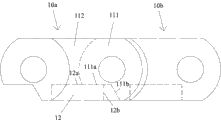
Fig. 7 is the schematic representation intention that is in adjacent two chain links of linear state among the embodiment one;
Fig. 8 is the plan view that is in adjacent two chain links of linear state among the embodiment one;
Fig. 9 is the schematic representation intention that is in adjacent two chain links of bent state among the embodiment one;
Figure 10 is the plan view that is in adjacent two chain links of bent state among the embodiment one;
Figure 11 is that the meagre type guiding that provides among the embodiment two asks the schematic representation of the chain link of chain to be intended to;
Figure 12 is the right elevation of chain link among Figure 11;
Figure 13 is the schematic representation of the chain link of the meagre type guiding holder chain that provides among the embodiment three;
Figure 14 is the right elevation of chain link among Figure 13.
Embodiment
For the purpose, technological scheme and the advantage that make the utility model embodiment clearer, below in conjunction with the accompanying drawing among the utility model embodiment, technological scheme among the utility model embodiment is clearly and completely described, obviously, described embodiment is the utility model part embodiment, rather than whole embodiments.Based on the embodiment in the utility model, those of ordinary skills are not making the every other embodiment who is obtained under the creative work prerequisite, all belong to the scope of the utility model protection.
Fig. 1 shows a kind of application scenarios of the guiding holder chain that present embodiment provides, this scene belongs to optical fiber exchange field, as shown in Figure 1, in order to realize in the exchange hole 31 on the outside line optical fiber power board 3, one end that the needs of outside line optical fiber 5 need be inserted in the exchange hole 31 is fixed in the corresponding linker 2, when linker 2 is inserted in the exchange hole 31, fixing outside line optical fiber 5 within it also is inserted in the exchange hole, because optical fiber itself is soft, therefore under the situation that does not add any other measure, the outside line optical fiber 5 that one end is fixed in the linker 2 is understood about generation in the process that this linker 2 moves or bending up and down, when the number of linker 2 and outside line optical fiber 5 more for a long time, outside line optical fiber 5 is easy to the phase mutual interference.The inventor proposes a kind of guiding holder chain after analyzing the problems referred to above, outside line optical fiber is placed in the guiding holder chain 1, can limit and leads outside circuit optical fiber 5 mobile, thereby can prevent the above-described problem from occurring.
The guiding holder chain that the utility model embodiment provides comprises a plurality of chain links that can connect rotatably mutually, this chain link has two respectively by the interconnective side plate of first transverse connection, wherein first transverse connection is positioned at the lower edge of side plate, adjacent two chain links overlap each other on width and can rotate mutually, the inner parking space that forms of above-mentioned a plurality of chain link that couples together, wherein, the plate of the formation overlap in adjacent two chain links on chain link side plate is arranged on the outside, the plate that constitutes overlap on another chain link side plate is arranged on inside, on the plate of inside formation overlap, the straight line attitude is set and keeps stopping surface and crooked attitude restrictions stopping surface, this straight line is kept stopping surface and is used for contacting with the upper surface of first transverse connection on the adjacent chain link, to keep the straight line attitude of connection, crooked attitude restrictions stopping surface be used for adjacent link on first transverse connection contact towards the side of this bending attitude restrictions stopping surface place chain link, with the crooked attitude of restriction chain.
Like this, owing to the guiding holder chain among the utility model embodiment can only be limited in linear state in the attitude scope of inside bending several angle, therefore settle flexible member may such as optical fiber, cable or flexible pipe within it to ask chain to be subjected to the restriction of moving range with guiding.
Describe content of the present utility model in detail with several specific embodiments below.
Embodiment one
The schematic representation of the guiding holder chain 1 of the meagre type that Fig. 2 provides for present embodiment, Fig. 3 is the schematic representation of a chain link 10 in the guiding holder chain 1 shown in Fig. 2, Fig. 4 is the plan view of chain link 10 shown in Fig. 3, Fig. 5 is the right elevation of chain link 10 shown in Fig. 3, and Fig. 6 is the worm's eye view of chain link 10 shown in Fig. 3.As shown in Figure 2, guiding holder chain 1 is made up of a plurality of chain links that can connect rotatably mutually 10, and adjacent two chain links 10 overlap on width each other.The following while describes chain link 10 in the present embodiment in detail with reference to Fig. 2 to Fig. 6.This chain link 10 has pair of side plates 11, and this lower edge to side plate 11 interconnects by first transverse connection 12.First transverse connection 12 had both served as the connected element between two side plates 11, can the flexible member may such as optical fiber that be placed in chain link inside be supported again, in order to avoid be bent downwardly.
Side plate 11 comprises aduncate plate 111 and bandy plate 112, please be simultaneously with reference to Fig. 1, when two adjacent chain links 10 overlap, bandy plate 112 on the side plate of previous chain link is positioned at the outside of overlap, aduncate plate 111 on the side plate of the chain link in back is positioned at the inside of overlap, be the inner plate that is arranged on that aduncate plate 111 constitutes adjacent two chain links overlap joint zone, bandy plate 112 constitutes the outside plate that is arranged in adjacent two chain links overlap joint zone.
In practice, overlap joint between adjacent two chain links and rotatable connection can be adopted following specific implementation: at the arranged outside swivel pin 113 of the aduncate plate 111 of the side plate 11 of chain link 10, in bandy plate 112, hinging hole 114 is set, make two adjacent chain links 10 by previous chain link hinging hole 114 and the swivel pin 113 of a back chain link realize hinged, thereby reach the purpose of overlap joint and rotation chain link.
In addition, for two adjacent in the restricted guidance holder chain 1 chain links 10 can not rotate up each other and can only be rotated down in certain angular range, on the plate that is positioned at the overlap joint intra-zone (aduncate plate 111 in the present embodiment for side plate) of chain link 10, the straight line attitude is set and keeps stopping surface 111a and crooked attitude restrictions stopping surface 111b.In adjacent two chain links 10, keep stopping surface 111a and crooked attitude restrictions stopping surface 111b contacts with first transverse connection 12 of previous chain link 10 respectively by the straight line attitude of a back chain link 10, these adjacent two chain links 10 can inwardly can only rotate to certain angle so that outwards can only rotate to the straight line attitude.
Describe the effect that the straight line attitude is kept stopping surface and crooked attitude restrictions stopping surface below in conjunction with Fig. 7 in detail to Figure 10.
Fig. 7 and Fig. 8 are respectively two adjacent link (being designated as 10a and 10b) schematic representation and the plan view that is in the straight line attitude, shown in Fig. 7 and 8, when chain link 10a and chain link 10b are in the straight line attitude, straight line attitude on the aduncate plate 111 of the chain link 10b in back is kept stopping surface 111a and is contacted with the upper surface 12a of first transverse connection 12 of previous chain link 10a, like this, because the straight line attitude is kept stopping surface 111a and the upper surface 12a of first transverse connection 12 and is contacted prevention chain link 10a and 10b from the continuation of straight line attitude relative to outwards rotating, even under the effect of gravity, the chain link that is positioned at the straightway part at guiding holder chain can not produce natural torsion downwards yet like this.And it is same because the effect of gravity, adjacent link can not be bent upwards naturally yet, thereby make the guiding holder chain in the present embodiment can keep the straight line attitude, and then make the flexible member may such as optical fiber, cable or flexible pipe that are placed in the guiding holder chain can keep the straight line attitude in the straightway part.
Fig. 9 to Figure 10 is respectively two adjacent chain links (being designated as 10a and 10b) schematic representation and the plan view that is in crooked attitude.As Fig. 9 and shown in Figure 10, when chain link 10a and 10b are in crooked attitude, crooked attitude restrictions stopping surface 111b on the aduncate plate 111 of the chain link 10b in back contacts with the upper surface 12a of first transverse connection 12 of previous chain link 10a, like this, because crooked attitude restrictions stopping surface 111a contacts and will stop chain link 10a and 10b to continue inwardly relative rotation from the position shown in Fig. 9 and Figure 10 with the upper surface 12a of first transverse connection 12, therefore adjacent two chain links can only inwardly rotation relatively in certain angle orientation.Be between the chain link at one section at the place of bending inwards owing to the effect of gravity is inwardly rotated at guiding holder chain like this, and be fixed on the angle rotatable position of a maximum, from but bending state that the guiding holder chain part of bending place can be maintained fixed and then make and be placed in the bending state that the flexible member may such as optical fiber, cable or flexible pipe in the guiding holder chain are maintained fixed.
In the present embodiment, the width of each chain link (i.e. distance between two side plates) can be accomplished less than 8mm, can save the space of switching equipment like this.
Embodiment two
Guiding holder chain that present embodiment provides and embodiment one difference only are: the outstanding toward each other in the direction constraint parts of two side plates that have a chain link in this guiding holder chain at least.
Figure 11 and Figure 12 are respectively the schematic representation and the right elevation of the chain link that has the constraint parts in the present embodiment, each outstanding constraint parts 13 toward each other in the direction of two side plates 11 in this chain link 10, and these constraint parts 13 are positioned at the upper limb of side plate 11.After settling flexible member may such as optical fiber, cable or conduit in the guiding holder chain, the constraint parts 13 on the chain link 10 can make the flexible member may that is placed in the chain link 10 emerge from the top of chain link than difficult.And owing to preferably leave the space between two constraint parts 13 on the same chain link 10, like this, the free time of flexible member may such as optical fiber, cable or conduit between two constraint parts 13 can be placed in the chain link, arrive the purpose of passing chain link, this has just made things convenient for installation.
In practice, can constraint parts 13 also can be set with on all chain links in the guiding holder chain constraint parts 13 being set all on the part chain link.
In the present embodiment, the width of each chain link (i.e. distance between two side plates) can be accomplished less than 8mm, can save the space of switching equipment like this.
Embodiment three
The guiding holder chain that present embodiment provides only is with embodiment one difference: have at least the upper limb of two side plates of a chain link to be connected by second transverse connection in this guiding holder chain.
Figure 13 and Figure 14 are respectively the schematic representation and the right elevation of the chain link that present embodiment latus inframedium upper limb is connected by second transverse connection.Particularly, the difference of the chain link among this chain link 10 and the embodiment one only is: between the upper limb of two side plates 11 of chain link 10 second transverse connection 14 is set, because second transverse connection 14 is set, make the steadiness of chain link 10 increase, and second transverse connection 14 can also serve as the crimp that is similar among the embodiment two to be used, and can further be limited in moving up and down of ductility parts such as optical fiber, cable or flexible pipe in second transverse connection 14.Just, when flexible member may such as optical fiber, cable or flexible pipe are passed chain link 10, can only penetrate wherein from the side of chain link 10 owing to the setting of second transverse connection 14.
In the present embodiment, the width of each chain link (i.e. distance between two side plates) can be accomplished less than 8mm, can save the space of switching equipment like this.
The above only is a preferred implementation of the present utility model; should be pointed out that for those skilled in the art, under the prerequisite that does not break away from the utility model principle; can also make some improvements and modifications, these improvements and modifications also should be considered as protection domain of the present utility model.