Background technology
With regard to the use habit of present personal computer, mouse is one of indispensable input equipment, people are that the input equipment of " MOUSE " is translated as " mouse " favorably with original text, promptly refer to it can as mouse flexibly, replace our finger to do that many operational computations machines are necessary to click work.In addition, since the mechanical mouse of the first generation, the displacement induction module of mouse has also experienced a plurality of developing stage such as ray machine, photoelectricity, can utilize wireless transport module and computing machine to carry out the signal transmission even.
Common mechanical formula mouse is to utilize ball in disk coder glide direction and the distance of mouse pointer on screen that convert of moving; Optical mouse then utilizes red light emitting diode to light shine on the plane, in the regular hour, receive the picture of passing back, with deciding mouse to move how many distances, in other words, mouse generally habitual cursor move mode, be whole mouse must be moved towards the corresponding moving direction of cursor, under the detecting of mobile induction module, reach the purpose of controlling cursor.
Simultaneously, constantly towards aspect development such as location utmost point precision, external form personalizations, allowing originally can only be as supporting role's mouse for mouse, the existing trend that becomes the desk device main force gradually, and this is also representing and is using the time of operation mouse also to increase thereupon.
Though there is the trend of increase the time of operation mouse, mouse on the market only provides the simple function of mouse beacon mostly on the function of operation at present.Therefore, each family manufactures the manufacturer of mouse in recent years, in order to allow mouse can have more function, and then at the front end of mouse mouse roller is set.
Mouse roller can utilize finger that mouse roller is operated, and uses and controls the relevant computer program or the function of interface neatly.For example, the user is when browsing page, and the may command mouse roller rolls forward or rolls backward, advances back control webpage and scrolls up or downward scrolling.
Therefore, mouse function and convenience can be more more during diversification, then can improve the surcharge or the convenience of mouse, allow the user operates more smoothly, and improve consumer's desire to purchase, and then promote enterprise and make a profit.
The utility model content
The utility model has disclosed a kind of mouse.Mouse comprises body, sensing module and first processing module.Sensing module is arranged in the body, and sensing module comprises image acquisition unit, and it can be in order to capture at least one coding image of corresponding coding pattern.First processing module is electrically connected to image acquisition unit, in order to produce the decoding signal according at least one coding image.
First processing module can comprise the image identification unit, and its image identification unit is electrically connected to image acquisition unit.Moreover mouse of the present utility model can further comprise light emitting module, in order to towards the coding pattern irradiation light.And image acquisition unit fechtable correspondence is through at least one coding image of the coding pattern of irradiation.At last, the image identification unit can become the decoding signal with the coding video conversion that image acquisition unit captured according to algorithm.Wherein coding pattern can be a two-dimensional bar.This image identification unit is the image identification element that at least one coding video conversion is become the decoding signal according to algorithm.
Mouse of the present utility model can further comprise light emitting module, in order to towards object illumination light, and a plurality of reflected images of the corresponding object through irradiation of image acquisition unit and then acquisition.First processing module is to judge the image processing element of mouse moving direction according to these reflected images.
In this embodiment, mouse of the present utility model can further comprise second processing module, and it is to be electrically connected to image acquisition unit.When light emitting module during towards object illumination light, a plurality of reflected images of the corresponding object through irradiation of image acquisition unit and then acquisition.Second processing module can be judged the mouse moving directions according to a plurality of reflected images of the object through shining.
Compared to prior art, mouse of the present utility model is except having general optical mouse have in order to the optical identification module of judging the function that mouse moves, more can utilize same group of optical identification module to come the image of coding pattern is carried out identification and decoding, and then increase the surcharge of mouse.
Can be further understood by following embodiment and accompanying drawing about advantage of the present utility model and spirit.
Embodiment
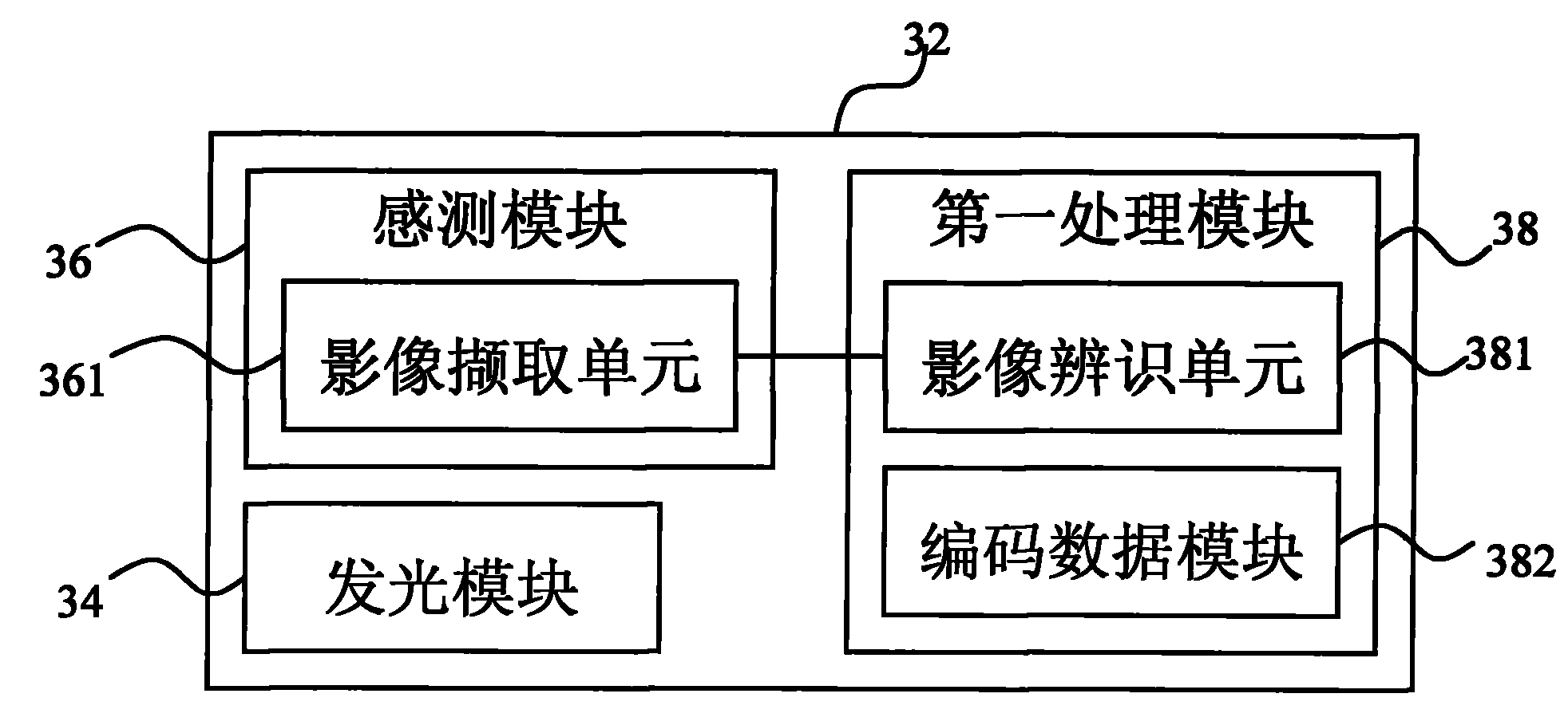
See also Figure 1A, Figure 1B, Fig. 1 C and Fig. 2.Figure 1A is the schematic appearance of the mouse 3 of the utility model one specific embodiment.Figure 1B is the top view of the mouse 3 among Figure 1A.Fig. 1 C is the following view of the mouse 3 among Figure 1A.Fig. 2 is the circuit block diagram of mouse 3 inside among Figure 1A.As Figure 1A, Figure 1B, Fig. 1 C and shown in Figure 2, this mouse 3 comprises body 32, light emitting module 34, sensing module 36 and first processing module 38.Wherein, the bottom surface of mouse 3 has sensing region 321.Sensing region 321 can allow light emitting module 34 and sensing module 36 positively carry out the action of optical detecting with object (not being illustrated among the figure).For example, sensing region 321 can be an opening or made by material transparent.
Light emitting module 34 is arranged in the body 32 of mouse 3.And in this specific embodiment, light emitting module 34 can comprise optical mirror slip 341 (but and nonessential) and luminescence unit 342.Luminescence unit 342 is in order to emission light.Wherein, the light that luminescence unit 342 is launched can pass optical mirror slip 341, but not especially as limit.
Sensing module 36 is arranged in the body 32 of mouse 3, and sensing module 36 comprises image acquisition unit 361.Wherein, image acquisition unit 361 can be an optical lens, but not as limit.
First processing module 38 is arranged in the body 32 of mouse 3, and first processing module 38 comprises image identification unit 381 and coded data module 382.In addition, the image identification unit 381 of first processing module 38 is electrically connected to the image acquisition unit 361 of sensing module 36.
Above-mentioned is to be described in detail and to describe at the introduction of mouse 3 outward appearances of the present utility model, internal module and the annexation of internal module.And following will being described in detail and describing at the practical manner and the means of this mouse 3.
See also Fig. 1 C, Fig. 2, Fig. 3 A, Fig. 3 B and Fig. 3 C.Fig. 3 A is the synoptic diagram of a specific embodiment of the object among Fig. 2.Fig. 3 B by the sensing module 36 of mouse 3 the synoptic diagram of acquisition reflected by objects image.Fig. 3 C by the sensing module 36 of mouse 3 the synoptic diagram of another reflected image of acquisition object.Shown in Fig. 1 C, Fig. 2, Fig. 3 A, Fig. 3 B and Fig. 3 C, has gauge point 42 on the surface 41 of object 4.When the sensing region 321 of mouse 3 moved to gauge point 42 tops on surface 41 of object 4, the luminescence unit 342 of its light emitting module 34 promptly can be to surface 41 throw lights of object 4.Wherein, light can be visible light, infrared light, laser light ... Deng, but not especially as limit.And this light is to see through the scope that optical mirror slip 341 stably shines all sensing regions 321.
When light is distributed in sensing region 321 fifty-fifty, and when illuminating sensing region 321, if mouse 3 moves, then the image acquisition unit 361 of sensing module 36 will capture a plurality of reflected images on the surface 41 of corresponding object 4.
For instance, at first, during the reflected image on the surface 41 that the image acquisition unit of sensing module 36 361 can the corresponding object 4 of acquisition, and transmit the image identification unit 381 of this reflected image to the first processing module 38 immediately.When the image identification unit 381 of first processing module 38 receives image acquisition unit 361 from sensing module 36 when capturing the reflected image on surface 41 of corresponding object 4, then can carry out the action of image location.For example, in the center of gauge point 42, build and put initial position line 43, but do not exceed in this way.
Then, when mouse 3 moves, another reflected image (shown in Fig. 3 C) on the surface 41 of the corresponding object 4 of image acquisition unit 361 acquisitions of sensing module 36, and the image identification unit 381 of first processing module 38 can transmit the image acquisition unit 361 of this another reflected image to sensing module 36 immediately.Then 381 of the image identification unit of first processing module 38 can compare analysis with these 2 reflected images.
In this embodiment, the reflected image among the reflected image among Fig. 3 C and Fig. 3 B compares analysis and can learn, the gauge point 42 of the reflected image of Fig. 3 C is to be offset initial position line 43 to the right.Therefore, the image identification unit 381 of first processing module 38 can judge that its mouse 3 is to move toward the left side.This will make the image identification unit 381 of the processing module 38 of winning immediately this signal is sent to other relevant module (not being illustrated among the figure) to carry out the processing of back segment program.
See also Fig. 1 C, Fig. 2 and Fig. 4.Fig. 4 is the synoptic diagram of another specific embodiment of the object among Fig. 2.In this embodiment, the coding pattern 52 on the surface 51 of object 5 also can be a two-dimensional bar, but not especially as limit.
In this specific embodiment, when the sensing region 321 of mouse 3 moved to coding pattern 52 tops on surface 51 of object 5, the luminescence unit 342 of its light emitting module 34 promptly can be to coding pattern 52 throw lights on the surface 51 of object 5.Wherein, light can be visible light, infrared light, laser light ... Deng, but not especially as limit.And this light is to see through optical mirror slip 341 stably the scope of sensing region 321 all to be included.
At this moment, light is distributed in sensing region 321 fifty-fifty and is illuminating sensing region 321.Therefore, when mouse 3 carries out when mobile, the image acquisition unit 361 of its sensing module 36 will capture a plurality of coding images of the coding pattern 52 of corresponding object 5.
When the image acquisition unit 361 of sensing module 36 captures the coding image of coding pattern 52 on surface 51 of corresponding object 5, can transmit the image identification unit 381 of these coding image to the first processing modules 38 immediately.When the image identification unit 381 of first processing module 38 receives image acquisition unit 361 from sensing module 36 when capturing the coding image of coding pattern 52 on surface 51 of corresponding object 5, then can carry out the temporary action of image identification or image.
For example, the left and right sides of coding pattern 52 includes beginning positioning strip font code 53 and finishes positioning strip font code 54.If the image acquisition unit 361 of sensing module 36 captures the coding image of coding pattern 52 on the surface 51 of corresponding object 5 when comprising beginning positioning strip font code 53 and finishing positioning strip font code 54, the coding image of coding pattern 52 of then representing the image acquisition unit 361 of sensing module 36 to capture the surface 51 of corresponding object 5 is complete coding pattern 52.At this moment, 38 of first processing modules can be according to the algorithm (but not especially as limit) about image identification, and the data that comprised in matching coding data module 382 databases, and the video conversion of will encode becomes to decipher signal.Afterwards, first processing module 38 is about to this decoding signal and is sent to relevant module (not being illustrated among the figure) so that carry out the back segment processing.
Then, if consider the situation when the coding image of coding pattern 52 that image acquisition unit 361 when sensing module 36 captures the surface 51 of corresponding object 5 might not comprise beginning positioning strip font code 53 and end positioning strip font code 54 simultaneously, this moment, the user can be constantly moves by X the sensing region 321 of mouse 3 toward Y, the end positioning strip font code 54 of and continuously inswept coding pattern 52 complete up to the sensing region 321 of mouse 3.
At this moment, the image of sensing module 36 can be sent to the image identification unit 381 of first processing module 38 with a plurality of coding images of the coding pattern 52 on the surface 51 of the corresponding object 5 of image acquisition unit 361 acquisition.The image identification unit 381 of first processing module 38 can utilize the mode (but not as limit) of image reorganization that a plurality of coding images are rearranged combination, and then complete coding pattern 52 is re-combined into.Then, the coding pattern 52 that is re-combined into is utilized the algorithm (but not especially as limit) and the interior data that comprised of matching coding data module 382 databases of image identification, the video conversion of will encoding becomes the decoding signal again.Afterwards, first processing module 38 is about to this decoding signal and is sent to relevant module (not being illustrated among the figure) so that carry out the back segment processing.
Please consult Fig. 5 more in the lump.Fig. 5 is the circuit block diagram of mouse 3 inside in another specific embodiment of the utility model.As shown in Figure 5, this mouse 3 can further comprise the second processing module 38a.The second processing module 38a can be external in outside the body 32 of mouse 3, and is electrically connected to the image acquisition unit 361 (but not as limit) of sensing module 36.Wherein the second processing module 38a comprises image identification unit 381a and coded data module 382a.Especially, the second processing module 38a can have the operation processing function identical with first processing module 38 (but also not as limit).Therefore, the second processing module 38a can respectively handle wherein a kind of calculation function with first processing module 38 respectively, to reduce the excessive burden of its operand.For example, first processing module 38 can be responsible for the judgment processing of the mobile form of mouse 3, and the second processing module 38a can be responsible for the judgment processing of the coding pattern of mouse 3.