Cutter clamping device
Technical Field
The utility model relates to the technical field of processing equipment, in particular to a cutter clamping device.
Background
In the prior art, a clamping device of a fluid polishing cutter props against a handle of the cutter from the side surface through a screw, so that the cutter is locked; however, in the polishing process, since the tool is continuously pressed by the abrasive, once the screw is loosened, the tool is easily and instantly taken out by the abrasive, thereby damaging the machine cylinder, and simultaneously causing the workpiece being processed to be damaged, and the abrasive is more doped with tool fragments.
In addition, if the mass production of cutter polishing needs to be carried out, each clamping device in the polishing machine needs a worker to lock the screws independently, which not only wastes time, but also influences the locking effect due to mutual interference among the screws, and causes low production efficiency, so that the design is not suitable for production and use.
SUMMERY OF THE UTILITY MODEL
In view of the above problems, an object of the present invention is to provide a tool clamping device, which can lock a tool without screws, and has the advantages of convenient operation and high mass production efficiency.
In order to achieve the purpose, the utility model provides a cutter clamping device which comprises a first clamping plate and a second clamping plate, wherein a clamping head is arranged on the first clamping plate, an opening is arranged on the clamping head, and a clamping space for clamping a cutter handle corresponding to the clamping head is formed in the clamping head; the second clamping plate is provided with a tapered hole corresponding to the clamping head, the tapered hole is provided with a smaller end and a larger end, and the larger end is over against the opening of the clamping head; under the assembled state of first splint and second splint, the chuck cover is established in the bell mouth, and with the inner wall of bell mouth supports each other and leans on, constitutes the centre gripping space is inwards compressed.
Preferably, the chuck comprises a first clamping piece and a second clamping piece, the first clamping piece is provided with a first outer side surface and a first inner side surface, the second clamping piece is provided with a second outer side surface and a second inner side surface, and the first inner side surface and the second inner side surface jointly form the clamping space; under the assembled state of first splint and second splint, first clamping piece and second clamping piece cover are established in the bell mouth, first lateral surface and second lateral surface support and lean on the bell mouth inner wall under the effect of bell mouth inner wall, first medial surface and second medial surface are close each other, realize the centre gripping space is inwards compressed.
Furthermore, the first inner side face and the second inner side face are two planes which are parallel to each other, and grooves for accommodating the corresponding cutter handles are formed in the two planes.
Preferably, the chuck is in a shape of a circular truncated cone, and the diameter of the cross section of the circular truncated cone is gradually reduced from one end connected with the first clamping plate to the other end.
Preferably, the clip and the first clamping plate are integrally formed from a plastics material.
Preferably, the second clamping plate is made of a metal material.
The utility model has the beneficial effects that: when the tool clamping device is used, the chuck is sleeved in the conical hole, the corresponding tool shank is placed in the clamping space, then the first clamping plate and the second clamping plate are pressed tightly up and down, at the moment, along with the relative displacement of the chuck and the conical hole, the inner wall of the conical hole where the chuck is abutted can be gradually contracted, the chuck is acted by the inward acting force of the inner wall of the conical hole, so that the clamping space is compressed inwards, and the tool clamping device clamps the corresponding tool shank; therefore, the cutter clamping device can lock the cutter without screws, can ensure that the cutter cannot be stressed to fall off, and ensures the safety of the machine cylinder and the grinding materials; meanwhile, the operation of locking screws is not needed, so that the operation is convenient, the labor is saved, and the processing efficiency is improved.
Drawings
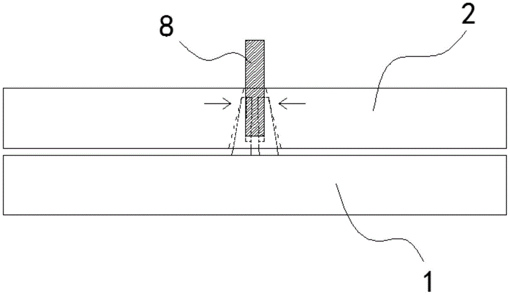
FIG. 1 is a schematic view of one embodiment of the present invention in an assembled state;
FIG. 2 is a schematic view of a first clamping plate of the embodiment of FIG. 1;
fig. 3 is a schematic view of a second clamping plate in the embodiment of fig. 1.
Description of the symbols: 1. a first splint; 2. a second splint; 3. a first clip piece; 4. a second clip; 5. a clamping space; 6. a groove; 7. a tapered hole; 8. a knife handle.
Detailed Description
The following is a detailed description of a preferred embodiment of the utility model:
as shown in fig. 1 to 3, the tool clamping device includes a first clamping plate 1 and a second clamping plate 2, the first clamping plate 1 and the second clamping plate 2 are arranged in parallel, wherein a clamping head is arranged on the first clamping plate 1, an opening is arranged on the clamping head, and a clamping space 5 for clamping a corresponding tool holder 8 is formed in the clamping head.
Specifically, the chuck includes first clamping piece 3 and second clamping piece 4, first clamping piece 3 has first lateral surface and first medial surface, second clamping piece 4 has second lateral surface and second medial surface, first medial surface and second medial surface are just right each other, form jointly between the two centre gripping space 5.
The second clamping plate 2 is provided with a conical hole 7 corresponding to the first clamping plate 3 and the second clamping plate 4, the conical hole 7 is provided with a smaller end and a larger end, and the larger end is opposite to the first clamping plate 3 and the second clamping plate 4; under the assembled state of first splint 1 and second splint 2, first clamping piece 3 and second clamping piece 4 cover are established in bell mouth 7, first lateral surface and second lateral surface support and lean on the bell mouth 7 inner wall under the restriction of bell mouth 7 inner wall, constitute first medial surface and second medial surface are close to each other.
This cutter clamping device is when using, establish conical hole 7 with first clamping piece 3 and 4 covers of second clamping piece in, will correspond cutter handle of a knife 8 simultaneously and place in the centre gripping space 5 between first clamping piece 3 and second clamping piece 4, then compress tightly first clamping piece 1 and second clamping piece 2 from top to bottom, along with the relative displacement of first clamping piece 3 and second clamping piece 4 and conical hole 7 this moment, first clamping piece 3 and second clamping piece 4 support and can contract gradually by the 7 inner walls of conical hole of department, make first clamping piece 3 and second clamping piece 4 receive the effort of 7 inner walls of conical hole and be close each other, thereby compression centre gripping space 5 makes this cutter clamping device press from both sides tightly corresponding cutter handle of a knife 8.
Therefore, the cutter clamping device can lock the cutter without screws, can ensure that the cutter cannot be stressed to fall off, and ensures the safety of the machine cylinder and the grinding materials; meanwhile, the operation of locking screws is not needed, so that the operation is convenient, the labor is saved, and the processing efficiency is improved.
In the embodiment, the chuck is in a circular truncated cone shape, and the diameter of the cross section of the circular truncated cone is gradually reduced from one end connected with the first clamping plate 1 to the other end; this shape more closely matches the shape of the inner wall of the conical bore 7.
In this embodiment, the first inner side surface and the second inner side surface are two planes parallel to each other, and grooves 6 for accommodating corresponding tool shanks 8 are formed on the two planes; under two planes that are parallel to each other, the contact area between the corresponding cutter handle 8 and the cutter clamping device can be maximized, so that the corresponding cutter handle 8 can be clamped more stably and is not easy to fall off.
In the embodiment, the first clamping plate 1 and the clamping head are integrally formed by plastic materials; correspond different cutters, need correspond the change to the shape of chuck on first splint 1, and make first splint 1 and chuck by plastic material integrated into one piece and can reduce the manufacturing degree of difficulty, improve production efficiency, simultaneously, the plastics material of chuck can provide certain elasticity, and first clamping piece 3 and second clamping piece 4 of being convenient for are out of shape under the restriction of bell mouth 7 inner wall, and then press from both sides tightly to cutter handle of a knife 8.
In the present embodiment, the second splint 2 is made of a metal material; because the second splint 2 has certain commonality corresponding to different cutters, chooses for use metal material can improve the intensity and the life of second splint 2, avoids frequently changing because of wearing and tearing.
The above description is only for the purpose of illustrating the preferred embodiments of the present invention and is not to be construed as limiting the utility model, but rather as the subject matter of the utility model is intended to cover all modifications, equivalents and alternatives falling within the spirit and scope of the present invention.