EP0005409B1 - Piezoelektrischer Wandler mit mechanischer Verstärkung für sehr niedrige Frequenzen und akustische Antenne - Google Patents
Piezoelektrischer Wandler mit mechanischer Verstärkung für sehr niedrige Frequenzen und akustische Antenne Download PDFInfo
- Publication number
- EP0005409B1 EP0005409B1 EP79400291A EP79400291A EP0005409B1 EP 0005409 B1 EP0005409 B1 EP 0005409B1 EP 79400291 A EP79400291 A EP 79400291A EP 79400291 A EP79400291 A EP 79400291A EP 0005409 B1 EP0005409 B1 EP 0005409B1
- Authority
- EP
- European Patent Office
- Prior art keywords
- base plate
- fact
- piezoelectric
- lateral plates
- transducer according
- Prior art date
- Legal status (The legal status is an assumption and is not a legal conclusion. Google has not performed a legal analysis and makes no representation as to the accuracy of the status listed.)
- Expired
Links
Images


Classifications
-
- G—PHYSICS
- G10—MUSICAL INSTRUMENTS; ACOUSTICS
- G10K—SOUND-PRODUCING DEVICES; METHODS OR DEVICES FOR PROTECTING AGAINST, OR FOR DAMPING, NOISE OR OTHER ACOUSTIC WAVES IN GENERAL; ACOUSTICS NOT OTHERWISE PROVIDED FOR
- G10K11/00—Methods or devices for transmitting, conducting or directing sound in general; Methods or devices for protecting against, or for damping, noise or other acoustic waves in general
- G10K11/08—Non-electric sound-amplifying devices, e.g. non-electric megaphones
-
- G—PHYSICS
- G10—MUSICAL INSTRUMENTS; ACOUSTICS
- G10K—SOUND-PRODUCING DEVICES; METHODS OR DEVICES FOR PROTECTING AGAINST, OR FOR DAMPING, NOISE OR OTHER ACOUSTIC WAVES IN GENERAL; ACOUSTICS NOT OTHERWISE PROVIDED FOR
- G10K9/00—Devices in which sound is produced by vibrating a diaphragm or analogous element, e.g. fog horns, vehicle hooters or buzzers
- G10K9/12—Devices in which sound is produced by vibrating a diaphragm or analogous element, e.g. fog horns, vehicle hooters or buzzers electrically operated
- G10K9/121—Flextensional transducers
Definitions
- the invention relates to piezoelectric transducers, for very low frequencies, between a few Hz and 500 Hz, which comprise a mechanical amplifier and antennas constructed with such transducers.
- the technical sector of the invention is that of the construction of acoustic devices used in particular in underwater acoustics.
- the objective of the present invention is to overcome this difficulty by mechanically amplifying the deformations of the piezoelectric transducers, so that it is possible to construct piezoelectric transducers of high power for very low frequencies.
- each stack of piezoelectric elements comprises a central fixed point and two half stacks located on either side of said fixed point.
- a transducer according to the invention comprises two identical sub-assemblies located on either side of the same base plate and symmetrical with respect thereto.
- the invention results in new piezoelectric transducers, transmitters or receivers, making it possible to obtain large amplitudes and therefore high powers in very low frequencies between a few Hz and 500 Hz, while using transducers having relatively small dimensions.
- the amplitude of the deformations of the piezoelectric stacks is multiplied by the mechanical amplifier associated with these stacks.
- This amplifier is constituted on the one hand by the two levers which multiply the amplitude of the oscillations by a coefficient equal to the ratio between the two lever arms and, on the other hand, by the elastic membrane which serves as a flag and which connects between them the free ends of the two levers so that when the spacing between the ends of the two levers varies in one direction or the other, this variation results in flexural deformations of the membrane and the amplitude of the deformations at center of the membrane is greater than the amplitude of the variations in spacing of the ends of the two levers.
- the elastic membrane constitutes a pavilion which can be placed in contact with water and which can therefore transmit water or pick up large amplitude acoustic waves while the deformations of the piezoelectric elements are much smaller than the deformations of the membrane flexible.
- the flexible membrane can be flat or, preferably, curved.
- the bending of the flexible membrane is obtained by means of a bending prestress of said plate, so that the latter remains constantly compressed even when the spacing between the two ends of the levers is maximum.
- the embodiment comprising two identical sub-assemblies arranged symmetrically with respect to the same base plate has the advantage of making it possible to reduce the thickness of this base plate.
- the transducers according to the invention make it possible to construct antennas comprising a base plate, flat or cylindrical, on which is arranged a network of transducers aligned along lines and / or columns.
- An advantage of the devices according to the invention lies in the fact that they are mechanical devices having several natural resonant frequencies including certain very low frequencies between a few Hertz and 500 Hz, which makes it possible to choose the lowest of these resonant frequencies and get a sensi curve SV bility measured in decibels with a pronounced peak, located in the very low frequency band.
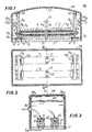
- FIGS. 1, 2 and 3 show a piezoelectric transducer intended either to emit or to pick up acoustic waves in water.
- This transducer comprises one or more stacks 1 of piezoelectric elements.
- each stack is composed of piezoelectric elements 2, for example plates of piezoelectric ceramic, between which electrodes 3 are inserted.
- the electrodes 3 are connected alternately on one or the other of two electrical conductors 4a and 4b, of opposite polarity.
- the elements 2 and the electrodes 3 are held tight by a central prestressing rod 5, of axis x x1 which is threaded at its two ends and by two nuts 6a, 6b which are screwed on the two threaded ends in order to put the rod 5 in tension.
- Such a stack of piezoelectric elements and electrodes is well known and we know that it deforms parallel to the axis x x1 if a sinusoidal voltage is applied between the conductors 4a and 4b and that reciprocally, a sinusoidal voltage between conductors 4a and 4b if the transducer serves as a receiver of acoustic waves.
- each piezoelectric element is limited by the nature of the materials. If one wants to emit or pick up very low frequency acoustic waves with sufficient power, it is necessary to use stacks comprising a very large number of elements, but then the transducers become very bulky.
- a submerged transducer makes it possible to obtain large amplitudes of deformation of the horn, that is to say of the active surface which is in contact with water and which transmits the acoustic waves to the water in the case of a transmitter or which receives the acoustic waves in the case of a receiver, and this result is achieved by means of a transducer whose dimensions remain relatively small, if we compare them to those which would be necessary to obtain the same amplitudes in the case of a traditional transducer comprising only a stack of piezoelectric elements.
- a transducer according to the invention comprises a very rigid base plate 7. It comprises two flat side plates 8a and 8b which are identical and perpendicular to the base plate 7, on the same side thereof. These side plates have, for example, a rectangular shape.
- the lower edge of each plate 8a and 8b is connected to the base plate, for example by means of plates 9a and 9b which are each composed of two half plates which are fixed to the base plate 7 by screws 10 and which enclose between them the lower edge of the plates 8a and 8b.
- Each plate 8a, 8b comprises, along its lower edge, immediately above the plates 9a and 9b, a thinning 11, constituted for example by two grooves 11a and 11b, located on either side of the plate such that the plates 8a and 8b can deform by pivoting around the thinning 11.
- the plates 8a and 8b are fixed in console on the plate 7 by semi-recesses.
- this semi-embedding can be replaced by an articulation around an axis parallel to the lower edge of each plate.
- each side plate such as 8a comprises, along its lower edge, a bead 12 of circular section, which is engaged in a groove 13 of circular section, hollowed out in the base plate 7.
- Two half plates 14a and 14b are screwed onto the plate 7 and maintain the bead 12 in its housing while allowing it to pivot.
- this articulation can be replaced by any other equivalent type of articulation.
- the stacks 1a and 1b extend above the base plate 7, perpendicular to the two plates 8a and 8b.
- the two axially opposite ends of the stack 1 are pressed against the internal faces of the two plates 8a and 8b slightly above the thinning 11.
- the support is produced by means of an intermediate support piece 15a, 15b .
- a support piece 15 is shown in perspective in FIG. 5. This piece has a first flat side face 16 which is pressed against one of the side plates 8 and a second side face 17, opposite to the face 16, which is pressed against one end of the stack 1.
- the face 17 is a portion of cylindrical surface, in an arc of a circle, so that the support of the stack on the support face is along a line which is the median generatrix 18 of the face 17.
- Each part 15 has two holes 19a and 19b for the passage of the extensions of the rod 5 which pass through the plates 8a and 8b. Nuts 20a and 20b are screwed onto these extensions to keep the stacks 1a and 1b in place.
- the cylindrical shape of the faces 17 of the support piece 15 makes it possible to precisely determine the support line 18 and therefore the distance which separates it from the line around which the plates 8a and 8b can pivot, that is ie thinning 11 or the center of the bead 12.
- the plates 8a and 8b act as levers, the thinning 11 or the beads 12 of which constitute the fulcrum, while the distance separating this fulcrum 18 constitutes the small arm of the lever. It is specified that the support pieces 15a and 15b can be reversed, so that their cylindrical face 17 is placed in contact with a side plate 8a or 8b.
- each stack 1a, 1b is made up of two symmetrical half stacks with respect to a central fixed point 21 which is constituted for example by a plate fixed to the base plate 7 by screws 22.
- the transducer shown in Figures 1, 2 and 3 further comprises a horn 23 which is the active surface, in acoustic contact with the water.
- This pavilion is constituted by an elastic and flexible membrane, for example a thin plate of spring steel having a thickness of a few millimeters.
- This plate is fixed by any means along each of its two lateral edges to an upper edge of one of the lateral plates 8a and 8b.
- the two lateral edges of the plate 23 are folded back to form folds 23a and 23b and these folds are held pinched between a plate 8a or 8b and a fixing plate 24a, 24b fixed to the plate 8a or 8b by screws 25. Screws 26 screwed into the thickness of the plates 8a and 8b can reinforce this fixing.
- the plate 23 is curved, the convex face being turned, preferably, on the side opposite to the base plate 7.
- a plate is used having a width in the direction parallel to the axis xx1 slightly greater than the spacing between the two side plates 8a and 8b and it is slightly compressed in the direction parallel to the axis x x1 before fixing it along the two upper edges of the plates 8a and 8b.
- the transducer according to FIGS. 1 to 3 comprises a sealed housing composed of two flanges 27a and 27b parallel to the plates 8a and 8b and of two lateral flanges 28a and 28b, visible in FIG. 3 and a flexible membrane 29, forming a skin of sealing, which envelops the flanges 27a, 27b, 28a, 28b and the roof 23.
- the skin 29 is made of a material having an acoustic impedance close to that of water so that it is acoustically transparent and that it does not disturb the transmission of waves between the water and the active surface of the roof 23. It is glued to the pavilion 23, so that it follows the movements thereof.
- the skin 29 is for example a thin skin of rubber or flexible plastic. A slight clearance exists between, on the one hand, the plates 8a, 8b and the roof 23 and on the other hand, the lateral faces 27a, 27b, 28a, 28b of the housing, so that the housing does not hinder movement flag and side plates 8a, 8b.
- the inside of the waterproof case is filled with gas. If the transducer is to be used in immersion, this gas is maintained in equilibrium with the outside, for example by means of a source of compressed gas provided with a regulator which is adjusted according to the depth.
- the two walls 27a and 27b of the housing can be eliminated and the membrane 29 can be glued directly to the two external faces 8a and 8b.
- the plates 8a and 8b constitute acoustically active surfaces.
- Figures 1 and 3 show a sealed connector 30 through which the electrical conductors 4a and 4b pass through the wall 28b.
- this transducer is as follows.
- the stack 1 deforms longitudinally along the axis x x1
- the deformations are communicated to the two levers 8a and 8b which deform by pivoting around their fulcrum.
- the displacements of the upper ends of the levers 8a and 8b are multiplied by the ratio between the two lever arms.
- the variations in spacing between the two upper edges of the two levers 8a and 8b produce flexural deformations of the elastic membrane 23.
- the displacements at the center of the membrane in the direction perpendicular to the base plate 7 are greater than the displacements of the ends upper two levers 8a and 8b.
- FIG. 6 represents measurements of the sensitivity SV of a transducer according to the invention as a function of the frequency. It is recalled that the sensitivity SV measured in decibels corresponds to 20 times the logarithm of the ratio between the acoustic pressure measured either in micro bar or in micro pascal and the voltage in volts.
- FIG. 6 shows on the abscissa a frequency range between 80 Hz and 180 Hz.
- the sensitivity measured according to the reference ⁇ bar per volt is represented on the left and on the right according to the reference ⁇ pascal / volt.
- a maximum sensitivity is obtained for a resonance frequency of the order of 125 Hz.
- FIG. 7 represents a longitudinal section of an alternative embodiment of a transducer according to the invention.
- An advantage of this embodiment is that it makes it possible to use a less rigid base plate 7 since it is bi-symmetrically stressed by the two half transducers.
- a transducer according to Figure 7 is very omnidirectional.
- the figures schematically represent an embodiment of an acoustic antenna comprising 25 transducers according to the invention, arranged in an array along five lines L1 to L5 and five columns C1 to C5.
- Each transducer is represented diagrammatically by a square whose two sides are in double line and represent the two side plates 8a and 8b of a transducer.
- All the transducers are fixed on the same rigid plate 31 which serves as a common base plate for all the transducers.
- the plate 31 can be flat, curved or cylindrical depending on the shape of the antenna.
- Two networks of transducers can be arranged symmetrically on either side of the plate 31.
Landscapes
- Physics & Mathematics (AREA)
- Engineering & Computer Science (AREA)
- Acoustics & Sound (AREA)
- Multimedia (AREA)
- Transducers For Ultrasonic Waves (AREA)
- Piezo-Electric Transducers For Audible Bands (AREA)
Claims (10)
Applications Claiming Priority (2)
| Application Number | Priority Date | Filing Date | Title |
|---|---|---|---|
| FR7813466A FR2425785A1 (fr) | 1978-05-08 | 1978-05-08 | Transducteurs piezo-electriques a amplification mecanique pour tres basses frequences et antennes acoustiques |
| FR7813466 | 1978-05-08 |
Publications (3)
| Publication Number | Publication Date |
|---|---|
| EP0005409A2 EP0005409A2 (de) | 1979-11-14 |
| EP0005409A3 EP0005409A3 (en) | 1979-11-28 |
| EP0005409B1 true EP0005409B1 (de) | 1981-04-15 |
Family
ID=9207972
Family Applications (1)
| Application Number | Title | Priority Date | Filing Date |
|---|---|---|---|
| EP79400291A Expired EP0005409B1 (de) | 1978-05-08 | 1979-05-08 | Piezoelektrischer Wandler mit mechanischer Verstärkung für sehr niedrige Frequenzen und akustische Antenne |
Country Status (4)
| Country | Link |
|---|---|
| US (1) | US4287582A (de) |
| EP (1) | EP0005409B1 (de) |
| DE (1) | DE2960263D1 (de) |
| FR (1) | FR2425785A1 (de) |
Cited By (1)
| Publication number | Priority date | Publication date | Assignee | Title |
|---|---|---|---|---|
| WO2007023262A1 (en) * | 2005-08-26 | 2007-03-01 | Halliburton Energy Services, Inc. | Apparatus and methods for generating acoustic waves |
Families Citing this family (28)
| Publication number | Priority date | Publication date | Assignee | Title |
|---|---|---|---|---|
| US4709359A (en) * | 1982-06-28 | 1987-11-24 | Magnovox Government And Industrial Electronics Company | End weighted reed sound transducer |
| EP0207095A4 (de) * | 1984-12-19 | 1989-03-13 | Gould Inc | Flextensioneller umwandler aus seltenen erden. |
| US4757548A (en) * | 1985-12-02 | 1988-07-12 | Fenner Jr Thomas C | Speaker system and dome-shaped enclosure therefor |
| WO1987005772A1 (en) * | 1986-03-19 | 1987-09-24 | The Secretary Of State For Defence In Her Britanni | Sonar transducers |
| US4764907A (en) * | 1986-04-30 | 1988-08-16 | Allied Corporation | Underwater transducer |
| WO1988003739A1 (en) * | 1986-11-07 | 1988-05-19 | Plessey Australia Pty. Limited | A composite sonar transducer for operation as a low frequency underwater acoustic source |
| FR2688112B1 (fr) * | 1988-04-28 | 1996-10-11 | France Etat Armement | Transducteurs electro-acoustiques directifs comportant une coque etanche en deux parties. |
| US5497357A (en) * | 1988-12-23 | 1996-03-05 | Alliedsignal Inc. | Shock-resistant flextensional transducer |
| US5742561A (en) * | 1990-05-10 | 1998-04-21 | Northrop Grumman Corporation | Transversely driven piston transducer |
| GB2348774B (en) * | 1990-11-28 | 2001-02-21 | Raytheon Co | Electro-acoustic transducers |
| CA2056586C (en) | 1990-12-24 | 2000-03-28 | David Justa Erickson | Moment bender transducer drive |
| US5126979A (en) * | 1991-10-07 | 1992-06-30 | Westinghouse Electric Corp. | Variable reluctance actuated flextension transducer |
| DE4135408A1 (de) * | 1991-10-26 | 1993-04-29 | Man Nutzfahrzeuge Ag | Verfahren zur umwandlung elektrischer energie in mechanische schwingungen, sowie vorrichtungen zur durchfuehrung dieses verfahrens |
| US5406531A (en) * | 1993-04-30 | 1995-04-11 | The United States Of America As Represented By The Secretary Of The Navy | Low frequency flex-beam underwater acoustic transducer |
| US6002648A (en) * | 1998-10-16 | 1999-12-14 | Western Atlas International, Inc. | Slotted cylinder marine siesmic method and source |
| US6717332B2 (en) | 2000-04-18 | 2004-04-06 | Viking Technologies, L.C. | Apparatus having a support structure and actuator |
| US6548938B2 (en) | 2000-04-18 | 2003-04-15 | Viking Technologies, L.C. | Apparatus having a pair of opposing surfaces driven by a piezoelectric actuator |
| US6759790B1 (en) * | 2001-01-29 | 2004-07-06 | Viking Technologies, L.C. | Apparatus for moving folded-back arms having a pair of opposing surfaces in response to an electrical activation |
| US6879087B2 (en) | 2002-02-06 | 2005-04-12 | Viking Technologies, L.C. | Apparatus for moving a pair of opposing surfaces in response to an electrical activation |
| US20030062071A1 (en) * | 2001-09-28 | 2003-04-03 | Sorbo Nelson W. | Dense-phase fluid cleaning system utilizing ultrasonic transducers |
| CN1781196A (zh) | 2003-04-04 | 2006-05-31 | 瓦伊金技术有限公司 | 一种智能材料致动器功的最佳化装置和方法 |
| US7591343B2 (en) | 2005-08-26 | 2009-09-22 | Halliburton Energy Services, Inc. | Apparatuses for generating acoustic waves |
| US20070064539A1 (en) * | 2005-08-26 | 2007-03-22 | Wei Han | Generating acoustic waves |
| US8189851B2 (en) | 2009-03-06 | 2012-05-29 | Emo Labs, Inc. | Optically clear diaphragm for an acoustic transducer and method for making same |
| JP6424001B2 (ja) * | 2010-10-04 | 2018-11-14 | ドクター ヒールシャー ゲーエムベーハー | 電気機械式複合高周波振動システム(vfhs)を締め付けるための装置及び方法 |
| US9094743B2 (en) * | 2013-03-15 | 2015-07-28 | Emo Labs, Inc. | Acoustic transducers |
| DE102015212686A1 (de) * | 2015-07-07 | 2017-01-12 | Robert Bosch Gmbh | Schallwandler |
| CN107154747B (zh) * | 2017-06-05 | 2018-10-30 | 西安交通大学 | 一种基于柔性放大结构的径向压电驱动器 |
Family Cites Families (6)
| Publication number | Priority date | Publication date | Assignee | Title |
|---|---|---|---|---|
| GB123145A (en) * | 1918-02-11 | 1919-02-11 | Creed & Co Ltd | Improvements in or relating to Means for Amplifying Small Movements, especially applicable for Producing Sounds. |
| US3277433A (en) * | 1963-10-17 | 1966-10-04 | William J Toulis | Flexural-extensional electromechanical transducer |
| US3258738A (en) * | 1963-11-20 | 1966-06-28 | Honeywell Inc | Underwater transducer apparatus |
| US3614486A (en) * | 1969-11-10 | 1971-10-19 | Physics Int Co | Lever motion multiplier driven by electroexpansive material |
| US3660809A (en) * | 1970-06-29 | 1972-05-02 | Whitehall Electronics Corp | Pressure sensitive hydrophone |
| US3649857A (en) * | 1970-07-30 | 1972-03-14 | Ibm | Mechanical energy storage and release device |
-
1978
- 1978-05-08 FR FR7813466A patent/FR2425785A1/fr active Granted
-
1979
- 1979-05-08 US US06/037,055 patent/US4287582A/en not_active Expired - Lifetime
- 1979-05-08 EP EP79400291A patent/EP0005409B1/de not_active Expired
- 1979-05-08 DE DE7979400291T patent/DE2960263D1/de not_active Expired
Cited By (1)
| Publication number | Priority date | Publication date | Assignee | Title |
|---|---|---|---|---|
| WO2007023262A1 (en) * | 2005-08-26 | 2007-03-01 | Halliburton Energy Services, Inc. | Apparatus and methods for generating acoustic waves |
Also Published As
| Publication number | Publication date |
|---|---|
| FR2425785B1 (de) | 1981-05-29 |
| EP0005409A3 (en) | 1979-11-28 |
| EP0005409A2 (de) | 1979-11-14 |
| DE2960263D1 (en) | 1981-05-07 |
| US4287582A (en) | 1981-09-01 |
| FR2425785A1 (fr) | 1979-12-07 |
Similar Documents
| Publication | Publication Date | Title |
|---|---|---|
| EP0005409B1 (de) | Piezoelektrischer Wandler mit mechanischer Verstärkung für sehr niedrige Frequenzen und akustische Antenne | |
| FR2581282A1 (fr) | Transducteur electromagnetique cylindrique a vibrations transversales | |
| CA1284531C (fr) | Hydrophones piezoelectriques de sensibilite accrue | |
| FR2663182A1 (fr) | Transducteur electro-acoustique immerge. | |
| FR3098810A1 (fr) | Liaison mécanique pour dispositif MEMS et NEMS de mesure d'une variation de pression et dispositif comprenant une telle liaison mécanique | |
| FR2571635A1 (fr) | Emetteur acoustique | |
| FR2623959A1 (fr) | Ensemble transducteur piezoelectrique bidimensionnel | |
| FR2688112A1 (fr) | Transducteurs electro-acoustiques directifs comportant une coque etanche en deux parties. | |
| EP0568592A1 (de) | Flextensioneller akustischer wandler für tiefe untertauchung. | |
| EP0118329B1 (de) | Geschwindigkeitshydrophon | |
| EP0434493A1 (de) | Verfahren zur Vermögenserhöhung von elektroakustischen Tieffrequenzwandlern und damit übereinstimmende Wandler | |
| EP3014606B1 (de) | Ultraschallwandler | |
| FR2688972A1 (fr) | Transducteurs electro-acoustiques comportant une coque emettrice flexible et etanche. | |
| CA2109465C (fr) | Dispositif d'etancheite de moteurs electro-acoustiques | |
| CH304763A (fr) | Transducteur ultrasonore à milieu de liaison liquide. | |
| EP0114764B1 (de) | Vorrichtung zur Reflexion von akustischen Wellen | |
| EP0694824B1 (de) | Uhrwerk mit elektroakustischem Umsetzer | |
| EP0799097B1 (de) | Vorgespannten ring akustischer wandler | |
| EP0403378B1 (de) | Kugelmembran-Rundstrahllautsprecher mit magnetostriktivem Doppelschicht-Bändchen | |
| CA2109466C (fr) | Procede et transducteurs pour emettre des ondes acoustiques basse frequence dans un liquide en immersion illimitee | |
| FR2776161A1 (fr) | Antenne d'emission acoustique annulaire demontable | |
| FR2656760A1 (fr) | Transducteur piezoelectrique. | |
| CA2314633A1 (fr) | Hydrophone a faible taux de distorsion | |
| FR2739521A1 (fr) | Transducteur electroacoustique et antenne de sonar equipee d'un tel transducteur | |
| FR2581819A1 (fr) | Transducteurs piezo-electriques de type tonpilz recepteurs a large bande et emetteurs et antenne de sonar composee de ces transducteurs |
Legal Events
| Date | Code | Title | Description |
|---|---|---|---|
| PUAI | Public reference made under article 153(3) epc to a published international application that has entered the european phase |
Free format text: ORIGINAL CODE: 0009012 |
|
| PUAL | Search report despatched |
Free format text: ORIGINAL CODE: 0009013 |
|
| AK | Designated contracting states |
Designated state(s): DE GB NL |
|
| AK | Designated contracting states |
Designated state(s): DE GB NL |
|
| 17P | Request for examination filed | ||
| GRAA | (expected) grant |
Free format text: ORIGINAL CODE: 0009210 |
|
| AK | Designated contracting states |
Designated state(s): DE GB NL |
|
| REF | Corresponds to: |
Ref document number: 2960263 Country of ref document: DE Date of ref document: 19810507 |
|
| PGFP | Annual fee paid to national office [announced via postgrant information from national office to epo] |
Ref country code: GB Payment date: 19910426 Year of fee payment: 13 |
|
| PGFP | Annual fee paid to national office [announced via postgrant information from national office to epo] |
Ref country code: NL Payment date: 19910531 Year of fee payment: 13 |
|
| PGFP | Annual fee paid to national office [announced via postgrant information from national office to epo] |
Ref country code: DE Payment date: 19910730 Year of fee payment: 13 |
|
| PG25 | Lapsed in a contracting state [announced via postgrant information from national office to epo] |
Ref country code: GB Effective date: 19920508 |
|
| PG25 | Lapsed in a contracting state [announced via postgrant information from national office to epo] |
Ref country code: NL Effective date: 19921201 |
|
| GBPC | Gb: european patent ceased through non-payment of renewal fee |
Effective date: 19920508 |
|
| NLV4 | Nl: lapsed or anulled due to non-payment of the annual fee | ||
| PG25 | Lapsed in a contracting state [announced via postgrant information from national office to epo] |
Ref country code: DE Effective date: 19930202 |
|
| PLBE | No opposition filed within time limit |
Free format text: ORIGINAL CODE: 0009261 |
|
| STAA | Information on the status of an ep patent application or granted ep patent |
Free format text: STATUS: NO OPPOSITION FILED WITHIN TIME LIMIT |