EP0006166A1 - Druckvorrichtung für einen Drahtdrucker und Drucker mit solchen Vorrichtungen - Google Patents
Druckvorrichtung für einen Drahtdrucker und Drucker mit solchen Vorrichtungen Download PDFInfo
- Publication number
- EP0006166A1 EP0006166A1 EP79101704A EP79101704A EP0006166A1 EP 0006166 A1 EP0006166 A1 EP 0006166A1 EP 79101704 A EP79101704 A EP 79101704A EP 79101704 A EP79101704 A EP 79101704A EP 0006166 A1 EP0006166 A1 EP 0006166A1
- Authority
- EP
- European Patent Office
- Prior art keywords
- loop
- pivot
- winding
- movement
- Prior art date
- Legal status (The legal status is an assumption and is not a legal conclusion. Google has not performed a legal analysis and makes no representation as to the accuracy of the status listed.)
- Granted
Links
- 230000007246 mechanism Effects 0.000 title claims abstract description 51
- 238000004804 winding Methods 0.000 claims abstract description 64
- 230000003068 static effect Effects 0.000 claims abstract description 5
- 239000000463 material Substances 0.000 claims description 11
- 238000010276 construction Methods 0.000 claims description 5
- XAGFODPZIPBFFR-UHFFFAOYSA-N aluminium Chemical compound [Al] XAGFODPZIPBFFR-UHFFFAOYSA-N 0.000 claims description 4
- 229910052782 aluminium Inorganic materials 0.000 claims description 4
- 239000004411 aluminium Substances 0.000 claims description 4
- 239000004642 Polyimide Substances 0.000 claims description 3
- 229920001721 polyimide Polymers 0.000 claims description 3
- 230000002441 reversible effect Effects 0.000 claims description 3
- 239000011248 coating agent Substances 0.000 claims description 2
- 238000000576 coating method Methods 0.000 claims description 2
- 239000000654 additive Substances 0.000 claims 1
- 230000000996 additive effect Effects 0.000 claims 1
- 239000011159 matrix material Substances 0.000 abstract description 7
- 241001422033 Thestylus Species 0.000 abstract 1
- 230000004907 flux Effects 0.000 description 4
- 230000009471 action Effects 0.000 description 2
- 238000010586 diagram Methods 0.000 description 2
- 230000000694 effects Effects 0.000 description 2
- 230000006872 improvement Effects 0.000 description 2
- 230000001133 acceleration Effects 0.000 description 1
- 230000008859 change Effects 0.000 description 1
- 230000003111 delayed effect Effects 0.000 description 1
- 230000005489 elastic deformation Effects 0.000 description 1
- 238000009413 insulation Methods 0.000 description 1
- 239000000314 lubricant Substances 0.000 description 1
- 238000005461 lubrication Methods 0.000 description 1
- 239000000696 magnetic material Substances 0.000 description 1
- 238000000034 method Methods 0.000 description 1
- 239000012858 resilient material Substances 0.000 description 1
- 238000000926 separation method Methods 0.000 description 1
- 230000001360 synchronised effect Effects 0.000 description 1
Images


Classifications
-
- B—PERFORMING OPERATIONS; TRANSPORTING
- B41—PRINTING; LINING MACHINES; TYPEWRITERS; STAMPS
- B41J—TYPEWRITERS; SELECTIVE PRINTING MECHANISMS, i.e. MECHANISMS PRINTING OTHERWISE THAN FROM A FORME; CORRECTION OF TYPOGRAPHICAL ERRORS
- B41J2/00—Typewriters or selective printing mechanisms characterised by the printing or marking process for which they are designed
- B41J2/22—Typewriters or selective printing mechanisms characterised by the printing or marking process for which they are designed characterised by selective application of impact or pressure on a printing material or impression-transfer material
- B41J2/23—Typewriters or selective printing mechanisms characterised by the printing or marking process for which they are designed characterised by selective application of impact or pressure on a printing material or impression-transfer material using print wires
- B41J2/27—Actuators for print wires
- B41J2/29—Actuators for print wires of moving-coil type
-
- B—PERFORMING OPERATIONS; TRANSPORTING
- B41—PRINTING; LINING MACHINES; TYPEWRITERS; STAMPS
- B41J—TYPEWRITERS; SELECTIVE PRINTING MECHANISMS, i.e. MECHANISMS PRINTING OTHERWISE THAN FROM A FORME; CORRECTION OF TYPOGRAPHICAL ERRORS
- B41J2/00—Typewriters or selective printing mechanisms characterised by the printing or marking process for which they are designed
- B41J2/22—Typewriters or selective printing mechanisms characterised by the printing or marking process for which they are designed characterised by selective application of impact or pressure on a printing material or impression-transfer material
- B41J2/23—Typewriters or selective printing mechanisms characterised by the printing or marking process for which they are designed characterised by selective application of impact or pressure on a printing material or impression-transfer material using print wires
- B41J2/235—Print head assemblies
- B41J2/25—Print wires
Definitions
- the invention relates to printing apparatus and in particular to a print mechanism for such apparatus.
- Wire printers are well known and comprise for example a plurality of print wires each movable longitudinally in a respective guide tube in the print head.
- the guide tubes are grouped together at one end to form a print matrix or print line and located at a print position so that selective movements of the wires can be used to effect printing of selected characters, or parts of characters.
- print wires are arranged in a row in a print head and the paper is moved in a direction perpendicular to the direction of the row of print wires. A character is printed by the correct selection and the timed actuation of the print wires synchronised with the movement of the paper.
- the paper is moved intermittently in a vertical direction with the print head incrementally or continuously moved horizontally across the paper selectively controlled to print one line at a time whilst the paper is stationary.
- Electromagnetic drivers or actuators forming part of the print mechanisms are energised to actuate each wire as needed to form the desired character.
- the actuators generally comprise an electromagnet having an armature fastened to its associated wire, energisation of which produces longitudinal movement of the wire in its guide. Further details of such a matrix print mechanism are to be found, for example, in United Kingdom Patent Specification No. 1,305,252.
- the principle limitation of this type of matrix print mechanism is the maximum repetition rate at which the print wire can be fired at the paper in a controlled way.
- the maximum acceleration of the wire is limited by the ratio of the applied force to the mass of the moving parts. This ratio is bounded by the fact that there is a limit to the energy that can be imparted to such an assembly by the magnetic circuit without unacceptable increase in heat or even the occurrence of physical distortion.
- the wire, having been fired bounces off the platten and returns to its original location retaining a significant proportion of the energy imparted to it. This energy must be dissipated and the part brought to rest before it can be fired again, or resonant conditions may be set up. The problem is alleviated to some extent by the use of return springs and mechanical dampers.
- the build-up of current in the energising winding is delayed by the inductance of the winding and a further limitation in speed is imposed.
- a print mechanism comprises a plurality of print elements each of which is selectively movable between a retracted non-print position and an extended print position by means of individually energisable actuators, characterised in that each actuator comprises a transformer core having a primary winding, a closed loop secondary winding, and means for generating a static magnetic field across a portion of the secondary winding, the direction of the field with respect to the secondary winding being such that, in operation, it reacts with secondary current induced in said winding as a result of energisation of the associated primary winding to apply a force on said portion in a predetermined direction, the secondary windings being constructed and arranged so that at least said portions are free to move under the influence of the applied forces, each print element being individually connected one to each of said portions of said secondary windings whereby movement of said portions causes corresponding movement of the associated print elements between retracted and extended positions.
- the secondary winding is in the form of a coil mounted for limited angular movement about a pivot, the direction of the applied magnetic field across a portion of the coil being such that, in the presence of induced secondary current, movement of the coil as a whole is produced about the pivot.
- the secondary winding is in the form of a self-supporting single conductive loop, the construction of the loop being such that a portion of the loop is elastically deformable in the plane of the loop, the magnetic field being applied across said portion in a direction such that in the presence of induced secondary current of a predetermined direction in said loop, said portion is deflected from a stable rest position to an unstable deflected position.
- FIG. 1 The principle of operation of the actuator incorporated in the print mechanism according to the present invention, is shown in the schematic diagram of Figure 1.
- a transformer core 1 of soft magnetic material carries a multi-turn primary winding 2 and a single turn secondary winding 3.
- the secondary winding may have more than one turn, the embodiments to be described utilise single turn secondaries of fairly robust formerless construction.
- the assembly of magnetic core 1 and windings 2 and 3 behave as a conventional transformer and may be analysed and designed as is well known in the transformer art.
- application of current Ip to primary winding 2 generates a changing magnetic field in the core 1 which in turn induces current Is in secondary winding 3 by transformer action.
- winding 3 By mounting winding 3 for rotation about a pivotal axis disposed at right angles to the plane of the coil, and situated at one end of the aforesaid limb (for example, in the vicinity of the transformer core), movement of the secondary coil about this axis can be controlled by application of primary current Ip to the primary winding 2.
- a hard print stylus attached to the moving part of the secondary coil or loop can thus be controlled for striking a ribbon/paper/platten combination to produce a print mark on the paper in the usual way.
- the secondary winding 3 is fixed, but elastically deformable so that the limb across which the magnetic field is applied is flexible or deflectable
- application of primary current Ip to the primary winding produces movement of the limb in a direction determined by the direction of applied primary current.
- printing can be achieved by means of a print stylus attached to the flexible or deflectable part of the secondary limb. Both these techniques are employed in the embodiments described below of inductively driven print mechanisms.
- any movement of the secondary loop whether by rotation about one axis or another, deformation of the loop itself or linear motion of the loop can be used to move a print element into and out of a print position.
- the print elements also may take any of several forms.
- print elements are in the form of short styli or 'anvils' carried by the secondary loops themselves.
- they may be in the form of extended print wires which are connected for driving purposes to the secondary loops but separately supported at the other end in a print head.
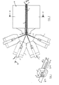
- Figures 2, 3 and 4 show various views of a print head mechanism in which each of a row of closely spaced print styli or 'anvils' is controlled by an individually driven pivoted loop arrangement.
- Figures 5 and 6 show two views of a print head mechanism in which each print stylus or 'anvil' is controlled by an individually driven flexible or deflectable arrangement in which the secondary loop is elastically deformed.
- Figures 7 and 8 show details of the mechanism shown in Figures 5 and 6.
- the first embodiment of the print mechanism is shown in plan view in Figure 2; as a section along line I-I in Figure 3, and a further section along line II-II in Figure 4.
- the print head is seen to comprise a number (in this case eight) of secondary loops 3, each formed from a thin aluminium sheet, or other suitable material, stacked together and mounted on a common pivot 6.
- the loops On one side of the pivot 6, the loops each have two elongated limbs 7 and 8°and are closely stacked parallel to each other.
- Each limb 7 carries a stylus 9 of hard material suitable for performing print operations on a ribbon/paper combination.
- the styli on the secondary loops together form a closely spaced print row as required in the wire printer art for performing printing operations.
- the secondary loops are free to rotate independently of each other through a small angle about pivot 6.
- Thin layers of wear-resistant material such as polyimide (not shown in the figures) insulate the loops from each other and provide lubrication. Alternatively insulation may be provided by an anodised layer on the aluminium loops.
- the loops are fanned out in two planes at right angles to each other on the side of the pivot remote from the print styli 9.
- pairs of loops are fanned out, or bent in opposite directions, with respect to the longitudinal axis of pivot 6.
- These pairs of secondary loops are additionally fanned out in a plane at right angles to the plane of the bends as shown in the plan view of the print head mechanism shown in Figure 2.
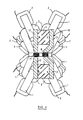
- the relative disposition of the individual secondary loops 3 and associated transformer cores 1 is further illustrated in the sectional view of Figure 4.
- Each transformer core 1 carries a multi-turn primary winding 2, which when energised induces a large current flow in its associated secondary loop 3.
- a permanent magnet structure 10 (shown generally in Figures 2 and 3 and in more detail in Figure 4) mounted on the opposite side of the pivot 6 from the transformer cores 1 provides a large magnetic field across the closely spaced parallel limbs 7 and 8 of all the secondary loops 3. More specifically, as shown in Figure 4, the magnet structure consists of two bar magnets 11 having pole-pieces 12 and 13 arranged to define two magnetic flux gaps in which the two closely stacked groups of elongated limbs 7 and 8 of the secondary loops are respectively located.
- the print head mechanism is mounted, as shown in Figure 3, with the row of print styli 9 adjacent and aligned at right angles to the longitudinal axis of a print platten 15 over which paper 16 to receive print is fed.
- a ribbon feed mechanism (not shown) increments an inked ribbon 17 interposed between the print styli 9 and paper in the usual manner.
- any print stylus 9 or combination of print styli can be caused to impact the interposed ribbon 17 and produce corresponding printed marks on paper 16 carried by platten 15.
- Relative movement between paper and print head necessary to print in rows may be achieved by any of a number of well known mechanisms.
- the print head mechanism may be held stationary and the platten carrying the paper moved past in the direction of its longitudinal axis with incremental line shifts between rows as required.
- the platten may be fixed and the print head mechanism itself moved in a print carriage along the length of the platten.
- the print carriage may support the ribbon feed mechanism, or this may be provided as an independent mechanism.
- the second embodiment of the invention is shown in perspective view in Figure 5 and in section along line III-III in Figure 6.
- the print head mechanism is seen to comprise, as in the previous embodiment, a number (in this case eight) of secondary loops 3 each formed from a thin aluminium sheet or other suitable material, and having an associated transformer core 1 carrying a secondary winding 2.
- the print action relies on selective elastic deformation of the secondary loops 3 rather than their rotation about a pivot.
- the secondary loops 3 are closely stacked together and each carries a print stylus 9 positioned midway along a specially formed flexible limb of the loop.
- Figure 7 shows a single secondary loop 3 having a flat main structural limb 18, two flat side portions 19, and a deflectable limb 20 carrying a print stylus 9 at its midpoint.
- the limb 20 is provided with two ninety degree twists, one at each end of the limb, between it and the two side portions 19 so that the width of the limb lies in the plane of the print stylus 9 and of the coil.
- the width of the loop is also reduced along the limb 20 to make it more flexible, but maintained relatively large elsewhere in order to reduce electrical resistance. Rotation of the plane of limb 20 through ninety degrees in this manner provides increased flexibility of the loop and enables a number of such loops (in this case eight) to be closely stacked together as shown in Figure 8.
- a crank 21 is provided in the main limb 18 of each loop for accommodating a transformer core 1.
- Each crank is progressively off-set from its neighbour to provide sufficient space for all the transformer cores 1.
- the cranks provide equally spaced transformer apertures 22 along each side of the stack of loops.
- the loops are electrically insulated from each other either by an anodised coating or by an insulating layer of wear resistant material such as polyimide which also acts as a lubricant between the loops in the stack.
- the transformer cores 1 are shown in Figure 5 threaded through transformer apertures 22, each uniquely associated with a secondary loop in the stack.
- Each transformer core 1 carries a multi-turn primary winding 2 which when energised induces a large current flow in its associated secondary winding 3.
- a permanent magnet structure 10 (shown generally in Figure 5 and in more detail in Figure 6) provides a large magnetic field across the closely spaced deflectable limbs 20 of the secondary loops. More specifically (as shown in Figure 6), the magnet structure consists of a single bar magnet 23 having pole-pieces 24 arranged to define a magnetic flux gap in which the closely stacked group of deflectable limbs 20 of the secondary loops are located.
- a resilient stop 25 ( Figure 6) provides a rest position for the secondary loops. In this embodiment, the elasticity of the loops is sufficient to hold them against the stop 14 when they are not being energised.
- the print head mechanism is mounted on a stationary or movable carriage 26 (part shown in Figure 6) as in the previous embodiment, the row of print styli 9 being adjacent and aligned at right angles to the longitudinal axis of a print platten 15 over which paper 16 is fed.
- a ribbon feed mechanism (not shown) increments an inked ribbon 17 interposed between print styli 9 and paper 16.
- One ink ribbon roller 27 is visible in Figure 5. Selective energisation of primary windings 2 causes a print stylus 9 or any combination of print styli to impact the interposed ribbon 17 and produce corresponding printed marks on the paper 16.
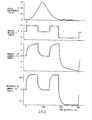
- Figure 9 of the drawings shows a graph of print stylus movement and the values of applied voltage, primary current Ip, secondary current Is throughout one cycle of motion of a print mechanism having pivoted secondary loops.
- 10 volts is applied to the primary winding of a selected print stylus.
- the primary current Is builds up to a maximum of 4 amperes and a secondary current Is of about 13U amperes is induced in the associated secondary loop. This large current co-acts with the applied magnetic field to move the print stylus towards the print position.
- the voltage is removed after being applied for 200 microseconds and the secondary loop contines its movement until the print stylus strikes the platten and rebounds therefrom.
- the print stylus typically moves 0.3 mm from its rest position to the platten.
- the voltage is re-applied to arrest the motion of the secondary loop until at around 550 microseconds the loop is approaching its rest position once again with a small residual velocity.
- the applied voltage is reversed thereby holding the loop against its stop. Small rebounds of the loop occur.
- 'At 900 microseconds from the start of the cycle the flux in the transformer core has decayed to zero and the reverse applied voltage can be removed or alternatively another cycle commenced.
- present print heads have performance limitations governed by the maximum repetition rate at which the print wires can be fired in a controlled manner.
- the present invention shows an improvement of three fundamental limitations of present matrix heads.
Landscapes
- Impact Printers (AREA)
- Electromagnets (AREA)
Applications Claiming Priority (2)
| Application Number | Priority Date | Filing Date | Title |
|---|---|---|---|
| GB7827243A GB2023353B (en) | 1978-06-19 | 1978-06-19 | Actuator for a printer |
| GB2724378 | 1978-06-19 |
Publications (2)
| Publication Number | Publication Date |
|---|---|
| EP0006166A1 true EP0006166A1 (de) | 1980-01-09 |
| EP0006166B1 EP0006166B1 (de) | 1982-03-17 |
Family
ID=10498028
Family Applications (1)
| Application Number | Title | Priority Date | Filing Date |
|---|---|---|---|
| EP79101704A Expired EP0006166B1 (de) | 1978-06-19 | 1979-06-01 | Druckvorrichtung für einen Drahtdrucker und Drucker mit solchen Vorrichtungen |
Country Status (6)
| Country | Link |
|---|---|
| US (1) | US4279520A (de) |
| EP (1) | EP0006166B1 (de) |
| JP (1) | JPS553995A (de) |
| CA (1) | CA1122061A (de) |
| DE (1) | DE2962274D1 (de) |
| GB (1) | GB2023353B (de) |
Cited By (1)
| Publication number | Priority date | Publication date | Assignee | Title |
|---|---|---|---|---|
| US6783432B2 (en) | 2001-06-04 | 2004-08-31 | Applied Materials Inc. | Additives for pressure sensitive polishing compositions |
Families Citing this family (4)
| Publication number | Priority date | Publication date | Assignee | Title |
|---|---|---|---|---|
| US4682903A (en) * | 1984-03-30 | 1987-07-28 | Nec Home Electronics Ltd. | Thin line printer typing head |
| JPH02222782A (ja) * | 1989-02-25 | 1990-09-05 | Toto Ltd | 浄化槽における空気採集体構造 |
| US5514922A (en) * | 1993-02-08 | 1996-05-07 | Sanden Corporation | Hermetic motor driven fluid apparatus having improved insulating structure |
| US5984210A (en) * | 1997-11-04 | 1999-11-16 | Caterpillar Inc. | Fuel injector utilizing a solenoid having complementarily-shaped dual armatures |
Citations (3)
| Publication number | Priority date | Publication date | Assignee | Title |
|---|---|---|---|---|
| US3285166A (en) * | 1964-12-18 | 1966-11-15 | Data Products Corp | High speed print hammer and bar magnet means |
| GB1149699A (en) * | 1967-04-12 | 1969-04-23 | Ibm | Electromagnetic actuator |
| DE2722275A1 (de) * | 1976-05-19 | 1977-12-01 | Gen Electric | Mosaikdruckerkoepfe mit gestapelten zungen |
Family Cites Families (21)
| Publication number | Priority date | Publication date | Assignee | Title |
|---|---|---|---|---|
| US2931963A (en) * | 1957-02-04 | 1960-04-05 | Bell & Howell Co | Linear induction motor servosystem for recording oscillograph |
| US2942163A (en) * | 1958-01-15 | 1960-06-21 | Morrison Montford | Constant-impedance alternating current relay motor-devices |
| US3117256A (en) * | 1961-01-03 | 1964-01-07 | Ibm | Electromechanical transducer |
| US3351006A (en) * | 1964-06-11 | 1967-11-07 | Honeywell Inc | Print hammer having braking means |
| DE1271440B (de) * | 1965-09-03 | 1968-06-27 | Arthur Klemt | Nadeldruckwerk fuer Schnelldrucker |
| GB1179419A (en) * | 1966-10-14 | 1970-01-28 | Int Computers Ltd | Flying Hammer Solenoid Systems for High Speed Printers |
| US3453463A (en) * | 1968-02-05 | 1969-07-01 | Gulf General Atomic Inc | Electrodynamic actuator |
| US3641583A (en) * | 1970-05-28 | 1972-02-08 | Teletype Corp | Electrodynamic transducer |
| US3741113A (en) * | 1971-06-25 | 1973-06-26 | Ibm | High energy print hammer unit with fast settle out |
| GB1398955A (en) * | 1972-02-24 | 1975-06-25 | Suwa Seikosha Kk | Hammer control mechanism of a printer |
| GB1321969A (en) * | 1972-06-01 | 1973-07-04 | Creed Co Ltd | Printing telegraph mechanism |
| US3754199A (en) * | 1972-09-29 | 1973-08-21 | Ibm | Magnetic mechanical amplifier |
| FR2218746A5 (de) * | 1973-02-19 | 1974-09-13 | Honeywell Bull Soc Ind | |
| GB1417827A (en) * | 1973-02-19 | 1975-12-17 | Citizen Watch Co Ltd | Wire printer |
| JPS5157238A (ja) * | 1974-11-15 | 1976-05-19 | Fujitsu Ltd | Dotsutopurintohanmamagunetsuto |
| CH612523A5 (de) * | 1975-06-30 | 1979-07-31 | Svenska Dataregister Ab | |
| US4014258A (en) * | 1975-08-29 | 1977-03-29 | Wassermann Carl I | High speed printing apparatus |
| JPS5240027A (en) * | 1975-09-26 | 1977-03-28 | Oki Electric Ind Co Ltd | High-speed printing equipment |
| US4022311A (en) * | 1975-11-19 | 1977-05-10 | Ncr Corporation | Electrodynamic actuator |
| US4019235A (en) * | 1976-04-30 | 1977-04-26 | Leonard Gregg | Piston puller |
| JPS5356511A (en) * | 1976-10-29 | 1978-05-23 | Sharp Kk | Dot printer |
-
1978
- 1978-06-19 GB GB7827243A patent/GB2023353B/en not_active Expired
-
1979
- 1979-04-24 CA CA000326207A patent/CA1122061A/en not_active Expired
- 1979-05-28 JP JP6509679A patent/JPS553995A/ja active Granted
- 1979-06-01 DE DE7979101704T patent/DE2962274D1/de not_active Expired
- 1979-06-01 EP EP79101704A patent/EP0006166B1/de not_active Expired
- 1979-06-12 US US06/047,852 patent/US4279520A/en not_active Expired - Lifetime
Patent Citations (3)
| Publication number | Priority date | Publication date | Assignee | Title |
|---|---|---|---|---|
| US3285166A (en) * | 1964-12-18 | 1966-11-15 | Data Products Corp | High speed print hammer and bar magnet means |
| GB1149699A (en) * | 1967-04-12 | 1969-04-23 | Ibm | Electromagnetic actuator |
| DE2722275A1 (de) * | 1976-05-19 | 1977-12-01 | Gen Electric | Mosaikdruckerkoepfe mit gestapelten zungen |
Non-Patent Citations (1)
| Title |
|---|
| IBM-Technical Disclosure Bulletin, Volume 13, Nr. 12, May 1971, New York D.E. RUTTER, SR. "Single-turn moving coil print magnet" page 3767. * |
Cited By (1)
| Publication number | Priority date | Publication date | Assignee | Title |
|---|---|---|---|---|
| US6783432B2 (en) | 2001-06-04 | 2004-08-31 | Applied Materials Inc. | Additives for pressure sensitive polishing compositions |
Also Published As
| Publication number | Publication date |
|---|---|
| GB2023353B (en) | 1982-10-06 |
| EP0006166B1 (de) | 1982-03-17 |
| GB2023353A (en) | 1979-12-28 |
| JPS6210834B2 (de) | 1987-03-09 |
| JPS553995A (en) | 1980-01-12 |
| US4279520A (en) | 1981-07-21 |
| DE2962274D1 (en) | 1982-04-15 |
| CA1122061A (en) | 1982-04-20 |
Similar Documents
| Publication | Publication Date | Title |
|---|---|---|
| JPS6213804Y2 (de) | ||
| US3217640A (en) | Electromagnetic actuating means for wire printers | |
| US4420266A (en) | Piezoelectric printer and piezoelectric multilam actuator used therein | |
| CA1083414A (en) | Matrix print head and solenoid driver | |
| US2686470A (en) | Hammer impelling means for high-speed printers | |
| US5793392A (en) | Printing apparatus and method | |
| US3994381A (en) | Wire matrix print head | |
| US3282203A (en) | Magnetically operated print hammers in high speed printers | |
| US3973661A (en) | Wire-matrix printers, and electromagnetic actuator mechanisms useful in such printers | |
| EP0006166B1 (de) | Druckvorrichtung für einen Drahtdrucker und Drucker mit solchen Vorrichtungen | |
| US4049108A (en) | Actuator for a matrix print head | |
| US4236836A (en) | Dot impact printer and actuator therefor | |
| US4218150A (en) | Matrix printer | |
| US4539905A (en) | Dot matrix line printer and print element driver assembly therefor | |
| US4732498A (en) | Needle matrix printer | |
| US4493568A (en) | Dot matrix printhead employing moving coils | |
| US4242955A (en) | Magnetically actuated equipment | |
| US4327638A (en) | Magnetically actuated equipment | |
| EP0210636B1 (de) | Zusammenbau elektromagnetischer Betätiger für die Hämmer von Schlagdruckern | |
| JPH03136870A (ja) | ドットラインプリンタ | |
| US4264219A (en) | Device for driving dot printing bars in a dot printer | |
| US3279364A (en) | Hammer construction | |
| KR0121784B1 (ko) | 와이어 도트 프린트 헤드 | |
| US4877342A (en) | Method of moving print elements in printheads and a printhead with moving mechanism for print elements | |
| JPS5678982A (en) | Printing wire driving mechanism |
Legal Events
| Date | Code | Title | Description |
|---|---|---|---|
| PUAI | Public reference made under article 153(3) epc to a published international application that has entered the european phase |
Free format text: ORIGINAL CODE: 0009012 |
|
| AK | Designated contracting states |
Designated state(s): DE FR GB IT |
|
| 17P | Request for examination filed | ||
| GRAA | (expected) grant |
Free format text: ORIGINAL CODE: 0009210 |
|
| AK | Designated contracting states |
Designated state(s): DE FR GB IT |
|
| PG25 | Lapsed in a contracting state [announced via postgrant information from national office to epo] |
Ref country code: IT Free format text: LAPSE BECAUSE OF FAILURE TO SUBMIT A TRANSLATION OF THE DESCRIPTION OR TO PAY THE FEE WITHIN THE PRESCRIBED TIME-LIMIT;WARNING: LAPSES OF ITALIAN PATENTS WITH EFFECTIVE DATE BEFORE 2007 MAY HAVE OCCURRED AT ANY TIME BEFORE 2007. THE CORRECT EFFECTIVE DATE MAY BE DIFFERENT FROM THE ONE RECORDED. Effective date: 19820317 |
|
| REF | Corresponds to: |
Ref document number: 2962274 Country of ref document: DE Date of ref document: 19820415 |
|
| PGFP | Annual fee paid to national office [announced via postgrant information from national office to epo] |
Ref country code: GB Payment date: 19890531 Year of fee payment: 11 Ref country code: FR Payment date: 19890531 Year of fee payment: 11 |
|
| PGFP | Annual fee paid to national office [announced via postgrant information from national office to epo] |
Ref country code: DE Payment date: 19890717 Year of fee payment: 11 |
|
| PG25 | Lapsed in a contracting state [announced via postgrant information from national office to epo] |
Ref country code: GB Effective date: 19900601 |
|
| GBPC | Gb: european patent ceased through non-payment of renewal fee | ||
| PG25 | Lapsed in a contracting state [announced via postgrant information from national office to epo] |
Ref country code: FR Effective date: 19910228 |
|
| PG25 | Lapsed in a contracting state [announced via postgrant information from national office to epo] |
Ref country code: DE Effective date: 19910301 |
|
| REG | Reference to a national code |
Ref country code: FR Ref legal event code: ST |
|
| PLBE | No opposition filed within time limit |
Free format text: ORIGINAL CODE: 0009261 |
|
| STAA | Information on the status of an ep patent application or granted ep patent |
Free format text: STATUS: NO OPPOSITION FILED WITHIN TIME LIMIT |