EP0006511A1 - Dispositif de nettoyage de tuyaux - Google Patents
Dispositif de nettoyage de tuyaux Download PDFInfo
- Publication number
- EP0006511A1 EP0006511A1 EP79101846A EP79101846A EP0006511A1 EP 0006511 A1 EP0006511 A1 EP 0006511A1 EP 79101846 A EP79101846 A EP 79101846A EP 79101846 A EP79101846 A EP 79101846A EP 0006511 A1 EP0006511 A1 EP 0006511A1
- Authority
- EP
- European Patent Office
- Prior art keywords
- rollers
- probe
- roller
- cleaning device
- wheel
- Prior art date
- Legal status (The legal status is an assumption and is not a legal conclusion. Google has not performed a legal analysis and makes no representation as to the accuracy of the status listed.)
- Granted
Links
- 238000004140 cleaning Methods 0.000 title claims description 25
- 230000033001 locomotion Effects 0.000 claims abstract description 45
- 239000000523 sample Substances 0.000 claims description 85
- 230000000295 complement effect Effects 0.000 claims description 4
- 230000000737 periodic effect Effects 0.000 claims description 4
- 230000005540 biological transmission Effects 0.000 claims description 2
- 238000005096 rolling process Methods 0.000 claims description 2
- 230000002441 reversible effect Effects 0.000 abstract description 4
- 241000512687 Anilius Species 0.000 abstract 4
- 241000270295 Serpentes Species 0.000 abstract 2
- 239000012530 fluid Substances 0.000 description 3
- 230000007935 neutral effect Effects 0.000 description 3
- 230000000694 effects Effects 0.000 description 2
- 230000001360 synchronised effect Effects 0.000 description 2
- XLYOFNOQVPJJNP-UHFFFAOYSA-N water Substances O XLYOFNOQVPJJNP-UHFFFAOYSA-N 0.000 description 2
- 239000000356 contaminant Substances 0.000 description 1
- 238000005553 drilling Methods 0.000 description 1
- 239000002184 metal Substances 0.000 description 1
Images


Classifications
-
- F—MECHANICAL ENGINEERING; LIGHTING; HEATING; WEAPONS; BLASTING
- F28—HEAT EXCHANGE IN GENERAL
- F28G—CLEANING OF INTERNAL OR EXTERNAL SURFACES OF HEAT-EXCHANGE OR HEAT-TRANSFER CONDUITS, e.g. WATER TUBES OR BOILERS
- F28G15/00—Details
- F28G15/04—Feeding and driving arrangements, e.g. power operation
-
- B—PERFORMING OPERATIONS; TRANSPORTING
- B08—CLEANING
- B08B—CLEANING IN GENERAL; PREVENTION OF FOULING IN GENERAL
- B08B9/00—Cleaning hollow articles by methods or apparatus specially adapted thereto
- B08B9/02—Cleaning pipes or tubes or systems of pipes or tubes
- B08B9/027—Cleaning the internal surfaces; Removal of blockages
- B08B9/04—Cleaning the internal surfaces; Removal of blockages using cleaning devices introduced into and moved along the pipes
- B08B9/043—Cleaning the internal surfaces; Removal of blockages using cleaning devices introduced into and moved along the pipes moved by externally powered mechanical linkage, e.g. pushed or drawn through the pipes
- B08B9/0436—Cleaning the internal surfaces; Removal of blockages using cleaning devices introduced into and moved along the pipes moved by externally powered mechanical linkage, e.g. pushed or drawn through the pipes provided with mechanical cleaning tools, e.g. scrapers, with or without additional fluid jets
Definitions
- the invention relates to a pipe cleaning device with a probe that can be inserted into a tube and a roller set comprising at least two rollers that can be rolled against one another on the probe and reversed in such a way that they either advance or retract the probe.
- a probe is understood here to mean an elongated, preferably elastically flexible structure of essentially constant cross section, which is suitable for being inserted into a tubular line or a bore in order to clean it or otherwise treat it from the inside.
- the term probe accordingly includes helical spring-like coils made of metal or plastic wire as well as hoses with which a fluid can be supplied under pressure to a tool arranged at the end of the hose.
- an essentially rigid lance can be used instead of a hose; this should therefore also fall under the term probe.
- a tool can be provided as a tool, which directs the fluid in one or more sharp jets against the inner wall of the pipeline or bore, or a drilling tool which is driven and / or cooled by the fluid.
- the pivotal movement of the roller carrier serves the sole purpose of adjusting the axial direction of the drum, and thus the direction in which the probe leaves the drum.
- the rollers have a neutral position in which their axes of rotation extend parallel to the probe passed between them. In this neutral position, the rollers resist longitudinal movement of the probe when the drum and probe are rotated by a motor associated with the drum. Starting from the neutral position, the rollers can be inclined by the same amount, but in opposite directions, optionally in two different directions, so that, without being directly driven, they can be fed at a given direction of rotation of the drum and the probe depending on the direction of the inclination -forcing retraction of the probe rotating between them.
- a feed movement of the probe can be easily converted into a retraction movement and vice versa by changing the inclined position of the rollers, so that, for example, a pipe section in which the tool attached to the probe encounters an obstacle is traversed several times can without having to reverse the direction of rotation of the drum.
- the invention is based on the knowledge that a hammering or pulsating additional movement, which is superimposed on the advancing or retracting movement of a probe, can considerably increase the effect of tools of the most varied kind arranged on the probe. This is especially true for the effects of high pressure water jets that emerge from a nozzle head at the end of a tubular or lance-shaped probe.
- the increase in effectiveness apparently has to do with the fact that rapidly successive reciprocating movements of the nozzle head or other pipe cleaning tool contribute to the rapid removal of contaminants which the tool has detached from the pipe wall.
- the invention is therefore based on the object of providing a pipe cleaning device which is capable of giving a probe gentle, overlapping, hammering or pulsating movements during a feed or retraction movement of a certain average speed with little effort.
- At least one of the rollers can be driven in rotation by a roller drive motor.
- the roller drive motor enables the probe to be given a feed or retraction movement even without rotating the probe.
- a rotatable drum for the probe is therefore not necessary; for this reason alone, the feed drive according to the invention can be designed simply, which has the further advantage that it is easy to transport.
- the invention is also applicable to a feed drive in which the actual feed or retraction movement, as in the known feed drive, consists in the probe being rotated about its own axis, preferably in the form of a lance, and thereby screwed between inclined rollers.
- the additional drive gives the probe an at least approximately rectilinear, periodic additional movement, the frequency and amplitude of which depend on the design of the additional drive and can thus be adapted to the respective application.
- the invention can further build on the feature of the known feed drive that the rollers are mounted on a roller carrier which is pivotable on a frame about an axis which extends at least approximately at right angles to the probe guided between the rollers.
- the probe is guided according to the invention between the rollers at a distance from the pivot axis of the roller carrier and the additional drive is an eccentric or crank drive driven by the roller drive motor, which periodically swings the roller carrier back and forth.
- the pivotability of the roller carrier does not have the purpose of setting the probe in a specific direction, but rather becomes the roller carrier pivoted back and forth to give the rollers and thus the probe the desired periodic additional movement.
- the last described embodiment of the invention can also build on the feature of the known feed drive that the roller drive motor is attached to the roller carrier and the axes of rotation of the rollers extend at an angle to the pivot axis of the roller carrier.
- a further development of the invention provides that a wheel is arranged coaxially with the roller driven by the roller drive motor, which wheel engages with a pinion of smaller diameter mounted on the roller carrier and drives a crank pin via this, which is connected to a connecting rod by a connecting rod pin connected to the frame is connected.
- roller drive motor is fastened to the frame and drives a wheel whose axis of rotation coincides with the pivot axis of the roller carrier, and that one of the rollers is in gear connection with this wheel.
- This development has the advantage that the inert mass of the roller carrier is particularly low, which contributes significantly to smooth running and a long service life of the feed drive according to the invention.
- the last-described development of the invention can be designed in a particularly simple manner in that the wheel is a friction wheel and the rollers are each mounted on a journal which is parallel to the axis of rotation of the wheel and which is guided radially displaceably with respect to the wheel on the roller carrier and towards the wheel is biased.
- the wheel can also be a gear and mesh with a pinion that is firmly connected to the one roller.
- the maximum speed of the reciprocating movement of the roller carrier is preferably greater than the speed at which the rollers roll on the probe. In this way, the advancing movement of the probe is not only accelerated and decelerated periodically, but temporarily transformed into a withdrawal movement. Conversely, a gradually advancing withdrawal movement of the probe is not only accelerated and decelerated by the back and forth additional movement, but is periodically converted into a feed movement.
- the additional drive has a second roller set comprising at least two rollers that can be rolled on the probe and that are synchronous can be driven with the rollers of the first roller set in a direction of rotation in which they endeavor to move the probe in the opposite direction to the feed direction of the first roller set, and that the rollers of the first roller set have a tread that can be rolled on the probe only in a first angular range, while The rollers of the second roller set have a tread that can be rolled on the probe only in a second angular range that is at least approximately complementary to the first angular range and of a different size.
- This embodiment is characterized by a particularly smooth running, since all the rollers can rotate continuously and there is also no need for any mass that is periodically accelerated and decelerated.
- the rollers are preferably each firmly connected to a gear wheel and are in a slip-free gear connection with one another via these gear wheels.
- the pipe cleaning device shown in Fig. 1 to 3 has the task of either advancing a probe 11, for example vertically downwards, or withdrawing it, for example vertically upwards, and thereby giving it a back and forth additional movement of high frequency.
- the device includes a frame 12 to which a lower guide tube 13 for the probe 11 is attached.
- the frame 12 can be arranged, for example, on a tube sheet of a boiler, the tubes of which are to be cleaned.
- the frame 12 can be attached to a trolley, carriage or the like, and also in such a way that the guide tube 13 lies obliquely or horizontally and the probe 11 is accordingly advanced and withdrawn in a direction deviating from the vertical.
- an axis 16 is arranged at a distance from and at a right angle to the guide tube 13.
- a rocker 17 is mounted, which belongs to a part of the pipe cleaning device which is referred to as roller carrier 18 and which can be moved back and forth with respect to the frame 12.
- a reduction gear 19 is attached to the rocker 17, to which a roller drive motor 21 is flanged.
- the reduction gear 19 produces a preferably continuously adjustable reduction ratio between the roller drive motor 21 and an output shaft 22, on which a gear 23 and a roller 24 are fastened.
- a crankshaft 28 is mounted parallel to the output shaft 22, on which a pinion 29 meshing with the gear 23 and a crank 31 are fastened.
- the crank 31 has a crank pin 32 on which a connecting rod 33 is mounted.
- the connecting rod 33 is adjustable in length in the manner of a turnbuckle and connects the crank pin 32 to a pin 34 fastened to the frame 12.
- a clamping jaw 36 is also pivotally mounted about an axis 37 parallel to the output shaft 22.
- a roller 38 is mounted on the clamping jaw 36, the axis of which is also parallel to the output shaft 22.
- the roller 38 corresponds in shape and size to the roller 24; both rollers 24 and 38 are made of plastic and are designed in the manner of rope pulleys so that they can gently guide and drive the probe 11.
- the probe 11 can additionally be guided in an upper guide tube 46 fastened to the clamping jaw 36, which has an interruption 47 so that the rollers 24 and 38 can rest against the probe 11.
- the feed drive described works as follows: If the roller drive motor 21 is turned on so that it. 1 drives the roller 24 clockwise, then the probe 11 is advanced downward. At the same time, the gear 23 drives the crankshaft 28 via the pinion 29 and this forms, together with the crank 31 and the connecting rod 33, an additional drive which swivels the rocker 17 back and forth about the axis 16, so that the rollers 24 and 38 have an im substantially vertical up and down additional movement is given, which is approximately straight due to the relatively large distance of the rollers from the axis 16 and overlaps the rotation of the rollers. As a result, the probe 11 performs an upward and downward additional movement during its downward feed movement.
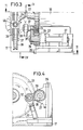
- the feed drive for a probe 51 shown in FIGS. 5 and 6 has a frame 52 which can also be provided with a chassis (not shown); however, this feed drive is so light that it can easily be carried to its place of use.
- a guide tube 53 for the probe 51 and a reduction gear 54 with a flanged roller drive motor 55 are fastened to the frame 52.
- a friction wheel 57 is attached, which has a race 58 of convex profile.
- a disc 59 is also freely rotatably mounted on the output shaft 56 and is the supporting component of a roller carrier 60 which can be pivoted with respect to the frame 52.
- the roller carrier 60 also includes a rocker 61 fastened to the disk 59, which is designed as a radial guide with respect to the output shaft 56.
- a first roller carriage 62 can be displaced on the rocker 61, to which a first bearing pin 63, which is parallel to the output shaft 56, is fastened.
- a first roller 64 is overhung on the journal 63.
- the roller 64 has the profile of a rope pulley; on the one hand it is in frictional engagement with the probe 51 and on the other hand as a satellite with the friction wheel 57. As shown, the diameter of the first roller 64 is preferably smaller than the diameter of the friction wheel 57.
- a second roller carriage 66 is also guided radially displaceably with respect to the output shaft 56; the guide designed for this purpose on the rocker 61 preferably the same on which the first roller carriage 62 can also be moved.
- a second bearing journal 67, on which a second roller 68 is overhung, is fastened to the second roller carriage 66 and parallel to the output shaft 56.
- a hitch pin 69 is attached to the side of the second roller carriage 66 facing away from the second roller 68.
- a third slide is guided on the rocker 61 radially to the output shaft 56, which is referred to below as a spring slide 71.
- a hitch pin 72 is fastened to the spring carriage 71 and is connected to the hitch pin 69 of the second roller carriage 66 by a tension spring 73.
- the tension spring 73 exerts a direction toward the output shaft 56. Force on the second roller carriage 66, and with this force, the second roller 68 presses against the probe 51. With the same force, the probe 51 presses against the first roller 64, creating a frictional connection between the probe 51 and the first roller 64 on the one hand and between this first roller and the friction wheel 57, on the other hand, is manufactured and maintained.
- the force of the tension spring 73 can be changed by means of an adjusting screw 74 which extends in the longitudinal direction of the rocker 61, is in threaded engagement with an extension 75 of the rocker and is mounted on the spring slide 71 in such a way that it takes it along.
- crank pin 76 is attached parallel to the bearing pin 63, the eccentricity of which can be adjustable.
- the crank pin 76 is connected to a bearing pin 77 fastened to the frame 52 by a connecting rod 78.
- roller drive motor 55 drives the friction wheel 57 clockwise according to FIG. 5 via the reduction gear 54, this rotates the first roller 64 counterclockwise, whereby the probe 51 is moved downward.
- the rotation of the first roller 64 via the crank pin 76 and the connecting rod 78 an up and down movement of the entire roller carrier 60, which results in an up and down additional movement of the probe 51.
- the feed drive for a probe 81 shown in FIGS. 7 to 10 has a box-shaped frame 82 to which a guide tube 83 for the probe is fastened.
- a reduction gear 84 with a flanged roller drive motor 85 is also attached to the frame 82.
- a clutch 86 which is shown as a simple flange clutch, but could also be a slip clutch, connects the reduction gear 84 to a shaft 87 which is mounted in the frame 82 and which relates to the shaft on the left in FIG. the probe 81 is a symmetrically arranged first pair of parallel waves 87, 87 '.
- a shaft 91 of a second pair of parallel shafts 91, 91 ' which is on the left in FIG. 7, is mounted vertically below the shaft 87, the right shaft 91' of which is arranged vertically below the right shaft 87 'of the first shaft pair.
- a gear 92 or 92 'and a roller 93 or 93' are attached to the shafts 91 and 91 '.
- the rollers 93 and 93 ' - each have a tread 94 or 94', which extends over only 160 angular degrees.
- the angular position of the rollers 89, 89 ', 93 and 93' is set such that the rollers 89 and 89 'always engage the probe 81 with their treads 90 and 90', only when the treads 94 and 94 'of the rollers 93 and 93' release the probe, as can be seen in FIG. 7.
- the angular ranges of 200 'of the treads 90 and 90' on the one hand are complementary to the angular ranges of 160 ° of the treads 94 and 94 'on the other hand, that is, they complement each other to 360 °, the reverse of what has been said above, ie the treads 94 and 94 'have a frictional connection with the probe 81 only when the running surfaces 90 and 90' release the probe.
- a pointer 95 or 95 ' is attached to the rollers 89 and 89'.
- the shafts 91 and 91 ' are not mounted directly in the frame 82, but in a slide 96 which is guided in the frame 82 so as to be displaceable at right angles to the common plane of the shafts mentioned.
- the carriage 96 is connected in an articulated manner by a tab 97 mounted on it to two levers 98 mounted on the frame 82.
- the two levers 98 are in turn articulated and connected with play in their longitudinal direction to a cross member 99 which is adjustable by means of an adjusting screw 100 which is rotatably mounted therein and screwed into the frame 82.
- the roller drive motor 85 is switched on in the direction of rotation in which it drives the roller 89 clockwise, the probe 81 is alternately moved downwards by a distance corresponding to the arc length of the running surfaces 90 and 90 ', for example 100 mm, then by one of the arc length Treads 94 and 94 'moved a corresponding distance of, for example, 80 mm, then moved down again by 100 mm, etc .; with each full rotation of the rollers, this results in a downward movement of 20 mm in the selected numerical example.
- the reverse direction of rotation of the rollers 89,89 ', 93 and 93' results in upward movement of each 1 00mm, faced downward movements of each 80mm, so that the probe 81 for each full rotation of the rollers about 20mm moved upward.
Landscapes
- Engineering & Computer Science (AREA)
- Mechanical Engineering (AREA)
- Chemical & Material Sciences (AREA)
- Combustion & Propulsion (AREA)
- General Engineering & Computer Science (AREA)
- Cleaning In General (AREA)
- Investigating Or Analyzing Materials By The Use Of Ultrasonic Waves (AREA)
- Transmission Devices (AREA)
- Investigating Or Analyzing Materials By The Use Of Magnetic Means (AREA)
- Catching Or Destruction (AREA)
Priority Applications (1)
| Application Number | Priority Date | Filing Date | Title |
|---|---|---|---|
| AT79101846T ATE12T1 (de) | 1978-06-08 | 1979-06-08 | Rohrreinigungsgeraet |
Applications Claiming Priority (2)
| Application Number | Priority Date | Filing Date | Title |
|---|---|---|---|
| DE19782825228 DE2825228A1 (de) | 1978-06-08 | 1978-06-08 | Vorschubantrieb fuer eine rohrschlange |
| DE2825228 | 1978-06-08 |
Publications (2)
| Publication Number | Publication Date |
|---|---|
| EP0006511A1 true EP0006511A1 (fr) | 1980-01-09 |
| EP0006511B1 EP0006511B1 (fr) | 1981-02-11 |
Family
ID=6041379
Family Applications (1)
| Application Number | Title | Priority Date | Filing Date |
|---|---|---|---|
| EP79101846A Expired EP0006511B1 (fr) | 1978-06-08 | 1979-06-08 | Dispositif de nettoyage de tuyaux |
Country Status (7)
| Country | Link |
|---|---|
| US (1) | US4266709A (fr) |
| EP (1) | EP0006511B1 (fr) |
| JP (1) | JPS54162854A (fr) |
| AT (1) | ATE12T1 (fr) |
| CA (1) | CA1122363A (fr) |
| DE (2) | DE2825228A1 (fr) |
| ZA (1) | ZA792825B (fr) |
Families Citing this family (19)
| Publication number | Priority date | Publication date | Assignee | Title |
|---|---|---|---|---|
| DE3404246A1 (de) * | 1984-02-07 | 1985-08-14 | Krauss-Maffei AG, 8000 München | Reinigungsvorrichtung fuer rohrwaffen |
| US5078162A (en) * | 1990-08-21 | 1992-01-07 | Teledyne Industries, Inc. | Cleaning apparatus for tubes |
| US5370290A (en) * | 1992-02-12 | 1994-12-06 | Gilliland; Malcolm T. | Wire feeder allowing for wire slippage without damaging wire |
| DE19605410C2 (de) * | 1996-02-14 | 1998-05-14 | Katimex Cielker Gmbh | Vorrichtung zum Aufnehmen und Abziehen eines biegeelastischen, strangförmigen Materials |
| EP0944853B1 (fr) * | 1996-12-11 | 2001-10-10 | Koninklijke KPN N.V. | Procede pour inserer un element de type cable dans un tube enroule dans ou sur un support |
| NL1004747C2 (nl) * | 1996-12-11 | 1998-06-15 | Nederland Ptt | Methode en inrichting voor het inbrengen van een kabelvormig element in een op of in een houder opgewonden langgerekte buisvormige omhulling. |
| NL1024113C2 (nl) * | 2003-08-14 | 2005-02-15 | Peinemann Equipment Bv | Lansinrichting met reciprocerende aandrijving. |
| AU2015292711B2 (en) | 2014-07-24 | 2019-08-15 | Stoneage, Inc. | Flexible tube cleaning lance positioner frame apparatus |
| US10024613B2 (en) | 2014-07-24 | 2018-07-17 | Stoneage, Inc. | Flexible tube cleaning lance positioner frame apparatus |
| US9630801B2 (en) | 2014-07-24 | 2017-04-25 | Stoneage, Inc. | Flexible tube cleaning lance drive apparatus |
| CN105952138B (zh) * | 2016-07-06 | 2017-10-17 | 福州幻科机电科技有限公司 | 一种手提式脚手架钢管表面清理机 |
| EP4123096B1 (fr) | 2016-11-28 | 2024-07-17 | Milwaukee Electric Tool Corporation | Dégorgeoir |
| US10272480B2 (en) | 2016-12-09 | 2019-04-30 | Stoneage, Inc. | Apparatus for remotely propelling a flexible lance into and out of a piping system |
| JP2020014982A (ja) * | 2018-07-23 | 2020-01-30 | 国立大学法人 鹿児島大学 | 縦管の内面洗浄装置 |
| CN218655922U (zh) | 2018-08-10 | 2023-03-21 | 米沃奇电动工具公司 | 排水管清洁机 |
| EP3956525A4 (fr) | 2019-04-19 | 2023-08-30 | Milwaukee Electric Tool Corporation | Mécanisme d'alimentation pour ensemble de nettoyage de drain |
| CN216586960U (zh) | 2019-05-15 | 2022-05-24 | 米沃奇电动工具公司 | 排水管清洁装置 |
| US11713932B2 (en) | 2020-08-18 | 2023-08-01 | Stoneage, Inc. | Flexible tube cleaning lance positioner frame apparatus |
| CN114934944A (zh) * | 2022-05-14 | 2022-08-23 | 张旭光 | 一种微型防水弯曲蛇形管装置 |
Citations (3)
| Publication number | Priority date | Publication date | Assignee | Title |
|---|---|---|---|---|
| US2102917A (en) * | 1934-09-19 | 1937-12-21 | Samuel V Rolland | Sewer rod |
| US3903912A (en) * | 1970-09-17 | 1975-09-09 | Hydro Vel Services Inc | Tube cleaning system |
| US3934448A (en) * | 1974-11-25 | 1976-01-27 | Hand Lowal L | Racked pipe reamer |
Family Cites Families (3)
| Publication number | Priority date | Publication date | Assignee | Title |
|---|---|---|---|---|
| US3387759A (en) * | 1967-02-24 | 1968-06-11 | Ferdinand C. Stedman | Wire feeding means |
| US3451089A (en) * | 1967-11-06 | 1969-06-24 | Conco Inc | Conduit cleaning apparatus |
| US3887163A (en) * | 1973-12-10 | 1975-06-03 | Rockwell International Corp | Apparatus for inserting cable or the like in conduits |
-
1978
- 1978-06-08 DE DE19782825228 patent/DE2825228A1/de not_active Withdrawn
-
1979
- 1979-06-06 CA CA329,210A patent/CA1122363A/fr not_active Expired
- 1979-06-07 ZA ZA792825A patent/ZA792825B/xx unknown
- 1979-06-08 DE DE7979101846T patent/DE2960157D1/de not_active Expired
- 1979-06-08 EP EP79101846A patent/EP0006511B1/fr not_active Expired
- 1979-06-08 US US06/046,683 patent/US4266709A/en not_active Expired - Lifetime
- 1979-06-08 AT AT79101846T patent/ATE12T1/de not_active IP Right Cessation
- 1979-06-08 JP JP7295879A patent/JPS54162854A/ja active Pending
Patent Citations (3)
| Publication number | Priority date | Publication date | Assignee | Title |
|---|---|---|---|---|
| US2102917A (en) * | 1934-09-19 | 1937-12-21 | Samuel V Rolland | Sewer rod |
| US3903912A (en) * | 1970-09-17 | 1975-09-09 | Hydro Vel Services Inc | Tube cleaning system |
| US3934448A (en) * | 1974-11-25 | 1976-01-27 | Hand Lowal L | Racked pipe reamer |
Also Published As
| Publication number | Publication date |
|---|---|
| JPS54162854A (en) | 1979-12-24 |
| EP0006511B1 (fr) | 1981-02-11 |
| DE2960157D1 (en) | 1981-03-26 |
| DE2825228A1 (de) | 1979-12-13 |
| ZA792825B (en) | 1980-07-30 |
| ATE12T1 (de) | 1981-02-15 |
| CA1122363A (fr) | 1982-04-27 |
| US4266709A (en) | 1981-05-12 |
Similar Documents
| Publication | Publication Date | Title |
|---|---|---|
| EP0006511B1 (fr) | Dispositif de nettoyage de tuyaux | |
| DE2746721C3 (de) | Rohrbiegemaschine | |
| DE2354398C3 (de) | Vorrichtung zur Vorbereitung eines auf seiner Oberfläche eine Zunderschicht u.a. Verunreinigungen aufweisenden Drahtes für den Ziehvorgang | |
| EP2289643B1 (fr) | Dispositif pour le pliage de longues pièces usinées | |
| AT411021B (de) | Walzstrasse zum walzen von metallischen rohren, stäben oder drähten | |
| DE3129903A1 (de) | Verfahren und vorrichtung zum herstellen von rohren mit abschnittweise wechselnden aussen- und innendurchmessern | |
| DE19532835C1 (de) | Vorrichtung zum Innenentgraten längsnahtgeschweißter Rohre und Profile mit drehendem Schneidring | |
| DE2502651A1 (de) | Richtmaschine | |
| DE2225118C2 (de) | Trennvorrichtung zum Unterteilen von durchlaufendem langgestrecktem Gut | |
| DE3141039C2 (de) | Vorrichtung zum Bewegen stangenförmigen Gutes, wie z.B. Rohre, Wellen und Draht, in Richtung seiner Längsachse, insbesondere als Ein- oder Auszungseinrichtung für Schäl- und/oder Richtmaschinen | |
| DE1652990B1 (de) | Einrichtung zum kontinuierlichen Wellen duennwandiger,insbesondere laengsnahtgeschweisster Glattrohre | |
| CH649013A5 (de) | Vorrichtung zum wellen von rohren. | |
| DE2553556C3 (de) | Verstellvorrichtung an fotografischen Vergrößerungs- oder Reprogeräten | |
| DE2518798B2 (de) | Biegekopf für Rohrbiegemaschinen | |
| DE10126411B4 (de) | Verfahren zum Walzen von Rohrluppen in einem Planetenschrägwalzwerk und Vorrichtung zum Zuführen von Rohrluppen in ein Planetenschrägwalzwerk | |
| DE862139C (de) | Walzwerk zum Walzen von nahtlosen Rohren aus Hohlbloecken | |
| DE3345029A1 (de) | Vorrichtung zum ausrichten von rohren und stangen | |
| DE79642C (fr) | ||
| DE3029447C2 (de) | Vorrichtung zum Wellen von Rohren | |
| DE2831202A1 (de) | Vorrichtung zum herstellen eines wellrohrkompensators | |
| DE71222C (de) | Verfahren und Vorrichtung zum Auswalzen von Röhren durch gleichzeitiges Längsund Querwalzen | |
| DE2840061C2 (de) | Zuführungs- und/oder Haltevorrichtung | |
| DE60023282T2 (de) | Reduzierwalzwerk mit drei Walzen zum Reduzieren eines durch Elektro-Widerstandschweissung erzeugten Rohres | |
| DE2214034B2 (de) | Vorschubeinrichtung für ein Pendelwalzwerk | |
| DE2825229A1 (de) | Vorschubantrieb fuer eine rohrschlange |
Legal Events
| Date | Code | Title | Description |
|---|---|---|---|
| PUAI | Public reference made under article 153(3) epc to a published international application that has entered the european phase |
Free format text: ORIGINAL CODE: 0009012 |
|
| AK | Designated contracting states |
Designated state(s): AT BE CH DE FR GB IT NL SE |
|
| 17P | Request for examination filed | ||
| ITF | It: translation for a ep patent filed | ||
| GRAA | (expected) grant |
Free format text: ORIGINAL CODE: 0009210 |
|
| AK | Designated contracting states |
Designated state(s): AT BE CH DE FR GB IT NL SE |
|
| REF | Corresponds to: |
Ref document number: 12 Country of ref document: AT Date of ref document: 19810215 Kind code of ref document: T |
|
| REF | Corresponds to: |
Ref document number: 2960157 Country of ref document: DE Date of ref document: 19810326 |
|
| PGFP | Annual fee paid to national office [announced via postgrant information from national office to epo] |
Ref country code: AT Payment date: 19820512 Year of fee payment: 4 |
|
| PGFP | Annual fee paid to national office [announced via postgrant information from national office to epo] |
Ref country code: FR Payment date: 19820527 Year of fee payment: 4 |
|
| PGFP | Annual fee paid to national office [announced via postgrant information from national office to epo] |
Ref country code: SE Payment date: 19820630 Year of fee payment: 4 Ref country code: NL Payment date: 19820630 Year of fee payment: 4 Ref country code: DE Payment date: 19820630 Year of fee payment: 4 Ref country code: CH Payment date: 19820630 Year of fee payment: 4 Ref country code: BE Payment date: 19820630 Year of fee payment: 4 |
|
| PG25 | Lapsed in a contracting state [announced via postgrant information from national office to epo] |
Ref country code: BE Effective date: 19830608 Ref country code: AT Effective date: 19830608 |
|
| PG25 | Lapsed in a contracting state [announced via postgrant information from national office to epo] |
Ref country code: SE Effective date: 19830609 |
|
| PG25 | Lapsed in a contracting state [announced via postgrant information from national office to epo] |
Ref country code: CH Effective date: 19830630 |
|
| PG25 | Lapsed in a contracting state [announced via postgrant information from national office to epo] |
Ref country code: NL Effective date: 19840101 |
|
| GBPC | Gb: european patent ceased through non-payment of renewal fee | ||
| NLV4 | Nl: lapsed or anulled due to non-payment of the annual fee | ||
| PG25 | Lapsed in a contracting state [announced via postgrant information from national office to epo] |
Ref country code: FR Free format text: LAPSE BECAUSE OF NON-PAYMENT OF DUE FEES Effective date: 19840229 |
|
| REG | Reference to a national code |
Ref country code: CH Ref legal event code: PL |
|
| PG25 | Lapsed in a contracting state [announced via postgrant information from national office to epo] |
Ref country code: DE Effective date: 19840301 |
|
| REG | Reference to a national code |
Ref country code: FR Ref legal event code: ST |
|
| PG25 | Lapsed in a contracting state [announced via postgrant information from national office to epo] |
Ref country code: GB Effective date: 19881118 |
|
| EUG | Se: european patent has lapsed |
Ref document number: 79101846.8 Effective date: 19850610 |
|
| PLBE | No opposition filed within time limit |
Free format text: ORIGINAL CODE: 0009261 |
|
| STAA | Information on the status of an ep patent application or granted ep patent |
Free format text: STATUS: NO OPPOSITION FILED WITHIN TIME LIMIT |