EP0014242B1 - Anordnung zur Unterdrückung von Wetterechos in einem Impulsdoppler-Folge-Radargerät - Google Patents
Anordnung zur Unterdrückung von Wetterechos in einem Impulsdoppler-Folge-Radargerät Download PDFInfo
- Publication number
- EP0014242B1 EP0014242B1 EP79104826A EP79104826A EP0014242B1 EP 0014242 B1 EP0014242 B1 EP 0014242B1 EP 79104826 A EP79104826 A EP 79104826A EP 79104826 A EP79104826 A EP 79104826A EP 0014242 B1 EP0014242 B1 EP 0014242B1
- Authority
- EP
- European Patent Office
- Prior art keywords
- phase
- input
- quadrature
- signal
- fed
- Prior art date
- Legal status (The legal status is an assumption and is not a legal conclusion. Google has not performed a legal analysis and makes no representation as to the accuracy of the status listed.)
- Expired
Links
- 238000002592 echocardiography Methods 0.000 title claims description 22
- 230000001629 suppression Effects 0.000 title description 3
- 230000001105 regulatory effect Effects 0.000 claims description 3
- 238000011156 evaluation Methods 0.000 description 12
- 238000000034 method Methods 0.000 description 6
- 239000003990 capacitor Substances 0.000 description 5
- 238000005259 measurement Methods 0.000 description 4
- 238000012546 transfer Methods 0.000 description 4
- 230000002596 correlated effect Effects 0.000 description 3
- 238000010586 diagram Methods 0.000 description 3
- 238000005516 engineering process Methods 0.000 description 3
- 230000005855 radiation Effects 0.000 description 3
- 230000002349 favourable effect Effects 0.000 description 2
- 230000001360 synchronised effect Effects 0.000 description 2
- 238000012360 testing method Methods 0.000 description 2
- 230000001427 coherent effect Effects 0.000 description 1
- 238000010276 construction Methods 0.000 description 1
- 230000001276 controlling effect Effects 0.000 description 1
- 230000001419 dependent effect Effects 0.000 description 1
- 230000008030 elimination Effects 0.000 description 1
- 238000003379 elimination reaction Methods 0.000 description 1
- 239000002245 particle Substances 0.000 description 1
Images


Classifications
-
- G—PHYSICS
- G01—MEASURING; TESTING
- G01S—RADIO DIRECTION-FINDING; RADIO NAVIGATION; DETERMINING DISTANCE OR VELOCITY BY USE OF RADIO WAVES; LOCATING OR PRESENCE-DETECTING BY USE OF THE REFLECTION OR RERADIATION OF RADIO WAVES; ANALOGOUS ARRANGEMENTS USING OTHER WAVES
- G01S13/00—Systems using the reflection or reradiation of radio waves, e.g. radar systems; Analogous systems using reflection or reradiation of waves whose nature or wavelength is irrelevant or unspecified
- G01S13/02—Systems using reflection of radio waves, e.g. primary radar systems; Analogous systems
- G01S13/50—Systems of measurement based on relative movement of target
- G01S13/52—Discriminating between fixed and moving objects or between objects moving at different speeds
Definitions
- the present invention relates to an arrangement for suppressing weather echoes according to the preamble of patent claim 1.
- a slave radar has to follow a moving target in a room filled with moving weather echoes, then not the fixed signs, but the weather echoes from the moving weather zones, i.e. the moving signals of a certain radial speed range are suppressed.
- This suppression can basically be carried out if, firstly, the difference between the radial speeds of target and weather echoes is sufficiently large and secondly, the speed of the weather echoes can be determined.
- the first condition cannot be influenced by the radar, but is often met in many applications.
- a known method for suppressing the weather echoes is based on single sideband modulation of the phase reference signal.
- a method is known from CH-PS No. 566012, for example, for determining the optimal compensation value in which the weather echo speed is determined in an additional weather echo detector. A number of discrete compensation frequency values are automatically tested and the one that is most suitable for compensating the weather echo in the tracking measurement port is selected.
- such a method proves to be disadvantageous because the measurement of the weather echo speed and the weather echo compensation cannot relate to the same room volume, since the weather echo gate has to be shifted in relation to the tracking measurement gate.
- an arrangement using this method works relatively slowly, since it is not single-minded and therefore has to test many unusable compensation values. Since the sign of the speed of the weather echoes can only be determined by testing the various compensation values, determination cannot be achieved.
- a further arrangement for suppressing weather echoes is known from US Pat. 3522604 known where a tracking system is described, which basically corresponds to the features of the preamble of claim 1.
- This tracking system relates in particular to a radar device without a quadrature channel, works with a single radar volume in two time-shifted working phases and has a discriminator for a frequency whose value is% per pulse repetition frequency fr.
- this proves to be disadvantageous if the pulse repetition frequency fr is to be switched systematically in order to avoid blind speeds.
- the tracking system with the frequency discriminator for the frequency fr / 4 can no longer function if the frequency discriminator is not also switched over, but this leads to a complex and difficult to implement solution.
- the purpose of the present invention is now to provide an arrangement for suppressing weather echoes which does not have these disadvantages.
- the arrangement according to the invention works purposefully and therefore enables the construction of a closed control loop.
- the weather echo measuring arrangement delivers an output signal which represents a signed measure for the deviation from the optimal value of the compensation frequency.
- the measurement of the weather echo speed therefore takes place directly in the tracking volume of the following radar device and also takes place despite the presence of a target.
- target echo and weather echo in the two radar volume halves, which result from the division of the volume in two, which is common in the technology of the subsequent radar, in order to generate error signals.
- the target echo is highly correlated in these two radar volume halves, i.e. it has the same phase position in both halves, since it originates from an object that is small compared to the radar pulse length.
- the weather echoes are very little correlated, i.e. The weather echoes have different phase positions, since only a small proportion of the reflecting particles in the weather zone cast an echo component in both halves of the radar volume at the same time.
- the stored echo signals of the two volume halves are now subtracted from one another, essentially only the movement component of the weather echoes (different phases) is obtained, while the target echo (same phase) is eliminated.
- the ratio of the radar beam width to the target width becomes extremely large at large distances and therefore, when the volume is halved in angle, is very favorable for measuring the weather echo coupler frequency according to the present invention. Because of the low strength of the target echoes to be evaluated, good weather echo suppression is particularly important, especially with long target distances.
- the radar volume 1 can be halved in terms of distance in two distance volume halves by a plane 2 oriented perpendicular to the axis of the radiation characteristic or by a plane 3 containing the axis of the radiation characteristic, in the latter case the side and the elevation angle is of particular importance.
- the Doppler frequency of the moving weather echoes is shown in the radar volume of the following radar together with the target echo, i.e. measured exactly where the weather echoes should also be compensated.
- the arrangement according to the invention can be used both with a distance measuring device and with an angle measuring device. It is only essential for this arrangement that the radar volume is divided into two practically identical halves A and B.
- the pulse Doppler slave radar device shown in FIG. 2 has an antenna ANT, a transceiver SEE, a distance evaluation device AWE and a compensation device for weather echoes KE.
- a duplex mixer DM connected to the antenna ANT is present in the transmitting / receiving device SEE, the output signal of which, via an adjustable intermediate frequency amplifier ZFV, is supplied on the one hand to the first input of a quadrature phase amplitude detector PDQ and on the other hand to the first input of an in-phase amplitude detector PDI with a reference signal from a second output of the duplex mixer DM via a coherence oscillator COHO and the compensation device KE on the one hand directly to the second input of the in-phase amplitude detector PDI and on the other hand via a 90 ° phase shifter PS to the second input of the quadrature-phase amplitude Detector PDQ is guided.
- the output signal of the quadrature phase amplitude detector PDQ is supplied on the one hand via a boxcar circuit THAO for the first half of the gate to the first input of a quadrature adder amplifier AVO and on the other hand via a boxcar circuit THBO for the second half of the gate to the first input of a quadrature differential amplifier DVQ, the output of Boxcar circuit THAO is connected to the second input of the differential amplifier DVO and the output of the boxcar circuit THBQ is connected to the second input of the adder amplifier AVQ.
- the output signal Uq of the adder amplifier AVQ is optionally fed via a low-pass filter to the first input of the evaluation device AWE and a further input of the compensation device KE, and the output signal Vq of the differential amplifier DVQ is fed via a second low-pass filter to the second input of the evaluation device AWE and the third input of the compensation device KE .
- the duplex mixer DM is, as usual, connected to a transmitter SD and to a stable local oscillator STALO.
- the output signal of the in-phase amplitude detector PDI is also supplied on the one hand via a boxcar circuit THAI for the first half of the gate to the first input of an in-phase adder amplifier AVI and on the other hand via a boxcar circuit TH BI for the second half of the gate to the first input of an in-phase differential amplifier DVI, the output of the boxcar circuit THAI is connected to the second input of the differential amplifier DVI and the output of the boxcar circuit THBI is connected to the second input of the adder amplifier AVI.
- the output signal Ui of the adder amplifier AVI is optionally fed via a low-pass filter to the third input of the evaluation device AWE and the fourth input of the compensation device KE, and the output signal Vi from the differential amplifier DVI is fed via a further low-pass filter to the fourth input of the evaluation device AWE and the fifth input of the compensation device KE .
- the intermediate frequency amplifier ZFV is regulated by a control circuit RS having an amplitude detector, a sum gate and a box car circuit.
- the output of the coherence oscillator COHO can be connected directly to the reference input of the transceiver SEE, i.e. be connected to the input of the phase shifter PS and the in-phase amplitude detector PDI.
- two squaring circuits QQS and IQS as well as four are each charged with one of the signals Uq, Vq, Ui and Vi suggested Doppler filter circuits DAO, DDO, DAI and DDI and an adder circuit FAS delivering a distance error voltage signal Sf, the first input of which with the output of an in-phase multiplier circuit IMS multiplying the output signals of the Doppler filter circuits DAI and DDI and the second input of which with the output of the output signals the Doppler filter circuits DAO and DDO multiplying quadrature multiplier QMS.
- the output signal of the Doppler filter circuit DAI is fed via the squaring circuit IQS to the first input of an adding circuit WAS
- the output signal of the Doppler filter circuit DAQ is fed via the squaring circuit QQS to the second input of the adding circuit WAS, the output of which each has a control input of the Doppler filter circuits DAQ, DDQ, DAI and DDI connected is.
- FIG. 3 shows the structure of a compensation device KE with a subtractor STH, the input side of which is connected on the one hand via the series circuit of a quadrature multiplier OMZ, a quadrature adder QA, a quadruple filter OF and a quadrature multiplier OMK and on the other hand via the series circuit of an in-phase multiplier I multiplier of an IMZ, a multiplier IMZ, IF and an in-phase multiplier IMK is supplied with the error voltage signal Sf.
- the output of the in-phase adder IA is connected to the second input of the quadrature multiplier OMK and the output of the ouadrature adder QA is connected to the second input of the in-phase multiplier IMK.
- the second input of the quadrature adder QA is supplied with the input signal Vq and the second input of the in-phase adder IA is supplied with the input signal Vi.
- the second input of the external multiplier OMZ is supplied with the input signal Uq and the second input of the in-phase multiplier IMZ is supplied with the input signal Ui.
- the output of the subtractor STH is connected via a low-pass filter TPF to the control input of the modulator MD, the output signal Sm of which is fed to the reference input of the transceiver SEE.
- the other input of the modulator MD is supplied with the output signal Sc of the coherence oscillator COHO, wherein the modulator MD can be, for example, a single sideband or a phase modulator.
- a target and echo signal received by the antenna ANT is processed in a known manner by the transceiver SEE and the distance evaluation device AWE.
- the signals are given which correspond to a distance evaluation, although the method according to the invention can be used both in a distance measuring device and in an angle measuring device.
- the elimination of the motion component of the target by subtracting the signals from the two radar volume halves A and B is based on the assumption that the target is centered in the radar volume in the antenna lobe. If a following error occurs, i.e. if the target is not in the center of the radar volume, this assumption is no longer met and when the signals from the two volume halves A and B are subtracted, a remainder of the target signal remains. This is undesirable and can be remedied by adding a weighted and signed portion of the sum of the signals from the two volume halves to the difference mentioned above.
- the sum signal Uq Uzq multiplied in the quadrature multiplier QMZ (FIG. 3) by the distance error voltage signal Sf as a weight voltage is therefore added in the quadrature adder QA to the difference signal Vq - ⁇ q ⁇ Uzq, which then results in a target signal delivers.
- a signal Urcq or Urci released from the target echo appears in the controller feedback loop to compensate for the weather echoes in the tracking gate, the signals Urci and Urcq differing by 90 ° in the weather echo phase, ie, where the sign of corresponds to the sign of the direction of movement of the weather echo and w represents the Doppler angular frequency of the weather echo.
- the output signal of the subtractor STH is formed as the difference between products, which are each formed from the signals Urci, Urcq and their filtered values Urci 'and Urcq'.
- the filters IF and OF have the same amplitude response A (w) and the same phase response ⁇ (w), which are determined by the complex transfer function G (w) and are also defined as real R (w) and imaginary components I (w) of the transfer function .
- the real parts of the input signals are multiplied as follows in the multipliers OMK and IMK: and It follows from this and The difference signal is in the subtractor STH formed, which has no AC voltage component.
- the sign of the DC voltage signal Uf corresponds to the direction of the weather echo speed, while its size depends on the imaginary component of the filter transfer function at the weather echo frequency w.
- the output signal Uf is proportional to the weather echo power.
- the output signal Ufn has a DC voltage component which corresponds to the sum of the weighed powers of the individual signals.
- FIG. 4 shows an ideal frequency discriminator characteristic with a linear course of I (w) between the values + Im (w) for + w min and -Im (w) for -w min , the reflection at the coordinate zero point of the sign reversal already mentioned by the Weather echo velocity vector corresponds.
- the ratio w max / w min (bandwidth) would have to be as large as possible and the ripple in between as small as possible. Linearity must be aimed for in the area of the zero point.
- Filter circuits with a filter characteristic for I (w) according to FIG. 4 can, for example, be implemented quite well by the circuits according to FIGS. 5 and 6. However, simple first-order high or low-pass filters are also sufficient.
- Filters of this type whose frequency curve of the imaginary part is proportional to the frequency at low frequencies, can be easily implemented with RC elements.
- FIG. 5 shows a possible implementation of a filter according to the formula as an active filter.
- the input of the filter is a connection that is connected on the one hand via the series connection of a resistor R2 and a capacitor C2 and on the other hand via a resistor R3 to the input of an operational amplifier, the output of which forms the output of the filter and via the parallel connection of a resistor R1 and a capacitor C1 is connected to its input.
- FIG. 6 shows a possible implementation of a filter according to the formula as an active filter.
- the input of this filter is a connection which is connected via a capacitor C11 and a resistor R11 to the input of an operational amplifier, the output of which forms the output of the filter and is connected to its input via the series connection of a capacitor C12 and a resistor R13.
- a resistor R12 being connected in parallel with the capacitor C12.
- a modulation circuit MD contains a single-sideband modulator, it outputs an output signal whose frequency corresponds to the sum of the frequency w ref, for example the COHO signal in the case of reception-coherent radar systems or the reference signal in the case of fully coherent systems, and the frequency w ck of a compensation signal which is dependent on the error voltage signal Ufn . Since the evaluation frequency of the output signals of the phase amplitude detectors PDQ and PDI (FIG.
- the frequency w ck of the compensation signal corresponds to the difference between the frequencies of their input signals
- the frequency w ck of the compensation signal is regulated in such a way that the frequency w ck becomes as equal as possible to the frequency w c .
- the weather echo Doppler signal is thus shifted into such a low frequency range that it is suppressed by the Doppler filters.
- the Doppler frequency of the target signal is also shifted by the same amount and must therefore be taken into account when controlling the pulse repetition frequency in order to avoid blind speeds. Since the mode of operation of the distance evaluation device AWE according to FIG. 2 is known per se, it need not be described in more detail here.
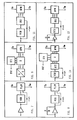
- FIGS. 7 to 12 A number of possibilities are conceivable for realizing the modulator MD, for example as a single-sideband modulator. They differ in the use of proportional or integral control, both in analog or digital technology. In the case of digital technology, the modulation clock pulse repetition frequency synchronous (PRF) or freely selectable.
- PRF modulation clock pulse repetition frequency synchronous
- FIGS. 7 to 12 The resulting six possible combinations are recorded in block diagrams in FIGS. 7 to 12.
- CT1 and CT2 represent counters, X a digital multiplier, A / D an analog / digital converter, PLLM a PLL modulator, DPM a digital phase modulator and VCO a voltage-controlled oscillator. Since these methods are known, they are not described here described in more detail.
- FIG. 13 shows the partial circuit of a monopulse follower radar with quadrature channel that is used for the lateral angle tracking.
- This arrangement has an antenna AN and a transceiver SE as well as an evaluation device AWE and a compensation device KE of the type already described.
- the transceiver SE there is a duplex mixer DU, which is connected via an input to a transmitter SEN and a stable local oscillator STALO and via suitable outputs to a coherence oscillator COHO, a comparator KP and an intermediate frequency amplifier V1 and V2.
- the comparator KP is connected to the antenna AN in a known manner.
- the output signal Sm of the compensation device KE is fed directly to the modulation inputs of two phase amplitude detectors PD1 and PD2 and via a 90 ° phase shifter PH to the modulation inputs of two further phase amplitude detectors PD3 and PD4.
- the signal inputs of the phase amplitude detectors PD1 and PD3 are connected to the output of the intermediate frequency amplifier V1 and the signal inputs of the phase amplitude detectors PD2 and PD4 are connected to the output of the intermediate frequency amplifier V2; this output is also connected to the input of a control circuit RG which comprises an amplitude demodulator, a sum gate and a boxcar circuit.
- the output signal of the control circuit RG is used to control the intermediate frequency amplifiers V1 and V2.
- phase amplitude detectors PD1, PD2, PD3 and PD4 are each connected via a low-pass filter TP1, TP2, TP3 and TP4 to an input of the evaluation device AWE.
- TP1, TP2, TP3 and TP4 are each connected via a low-pass filter TP1, TP2, TP3 and TP4 to an input of the evaluation device AWE.
- the difference is formed between the volume halves in the differential image circuits DVO and DVI, while in FIG. 13 it is already formed in the comparator KP.
Landscapes
- Engineering & Computer Science (AREA)
- Radar, Positioning & Navigation (AREA)
- Remote Sensing (AREA)
- Computer Networks & Wireless Communication (AREA)
- Physics & Mathematics (AREA)
- General Physics & Mathematics (AREA)
- Radar Systems Or Details Thereof (AREA)
Description
- Die vorliegende Erfindung betrifft eine Anordnung zur Unterdrückung von Wetterechos gemäss dem Oberbegriff des Patentanspruches 1.
- Hat ein Folgeradar ein bewegtes Ziel in einem von bewegten Wetterechos gefüllten Raum zu verfolgen, so sollen nicht die Festzeichen, sondern die Wetterechos aus den sich bewegenden Wetterzonen, d.h. die Bewegtzeichen eines bestimmten Radialgeschwindigkeitsbereiches unterdrückt werden. Diese Unterdrückung lässt sich grundsätzlich dann durchführen, wenn erstens die Differenz der Radialgeschwindigkeiten von Ziel- und Wetterechos genügend gross ist und zweitens die Geschwindigkeit der Wetterechos festgestellt werden kann. Die erste Bedingung ist vom Radar nicht beeinflussbar, wird aber in vielen Anwendungen oft erfüllt.
- Eine bekannte Methode zur Unterdrückung der Wetterechos beruht auf einer Einseitenbandmodulation des Phasenreferenzsignals. Zur jeweiligen optimalen Kompensationswertbestimmung ist beispielsweise aus der CH-PS Nr. 566012 eine Methode bekannt, bei der die Wetterechogeschwindigkeit in einem zusätzlichen Wetterechomesstorermittel wird. Dabei wird eine Anzahl diskreter Kompensationsfrequenzwerte automatisch durchgetestet und derjenige, der jeweils zur Kompensation des Wetterechos im Verfolgungsmesstor am besten geeignet ist, ausgewählt. Ein solches Verfahren erweist sich jedoch als nachteilig, weil die Messung der Wetterechogeschwindigkeit und die Wetterechokompensation sich nicht auf das gleiche Raumvolumen beziehen können, da das Wetterechomesstor gegenüber dem Verfolgungsmesstor verschoben sein muss. Zudem arbeitet eine Anordnung nach diesem Verfahren relativ langsam, da sie nicht zielstrebig ist und daher viele unbrauchbare Kompensationswerte durchtesten muss. Da das Vorzeichen der Geschwindigkeit der Wetterechos nur mittels Durchtesten der verschiedenen Kompensationswerte ermittelbar ist, ist eine Zielstrebigkeit nicht erreichbar.
- Eine weitere Anordnung zur Unterdrückung von Wetterechos ist aus der US-PS-Nr. 3522604 bekannt, wo ein Trackingsystem beschrieben ist, das grundsätzlich den Merkmalen des Oberbegriffs des Patentanspruches 1 entspricht. Dieses Trackingsystem betrifft insbesondere ein Radargerät ohne Quadraturkanal, arbeitet mit einem einzigen Radarvolumen in zwei zeitlich verschobenen Arbeitsphasen und weist einen Diskriminator für eine Frequenz auf, deren Wert % per Pulswiederholungsfrequenz fr beträgt. Dies erweist sich indessen als nachteilig, wenn zwecks Vermeidung von Blindgeschwindigkeiten die Pulswiederholungsfrequenz fr systematisch umgeschaltet werden soll. Das Trackingsystem mit dem Frequenzdiskriminator für die Frequenz fr/4 kann nämlich in einem solchen Fall nicht mehr funktionieren, wenn der Frequenzdiskriminator nicht ebenfalls umgeschaltet wird, was jedoch zu einer aufwendigen und schwer realisierbaren Lösung führt.
- Zweck der vorliegenden Erfindung ist es nun, eine Anordnung zur Unterdrückung von Wetterechos anzugeben, die diese Nachteile nicht aufweist.
- Dies wird erfindungsgemäss durch die im kennzeichnenden Teil des Patentanspruches 1 angegebenen Massnahmen erreicht.
- Vorteilhafte Ausgestaltungen der Erfindung sind in weiteren Ansprüchen angegeben.
- Die erfindungsgemässe Anordnung arbeitet zielstrebig und ermöglicht daher den Aufbau eines geschlossenen Regelkreises. Die Wetterechomessanordnung liefert ein Ausgangssignal, welches ein vorzeichenbehaftetes Mass für die Abweichung vom optimalen Wert der Kompensationsfrequenz darstellt. Die Messung der Wetterechogeschwindigkeit erfolgt daher direkt im Verfolgungsvolumen des Folgeradargerätes und geschieht auch trotz Anwesenheit eines Zieles.
- Dies ist möglich wegen der unterschiedlichen Korrelationseigenschaften von Zielecho und Wetterechos in den beiden Radarvolumenhälften, die durch die in der Technik des Folgeradars übliche Zweiteilung des Volumens zwecks Bildung von Fehlersignalen entstehen. In diesen beiden Radarvolumenhälften ist das Zielecho in hohem Mass korreliert, d.h. es weist in beiden Hälften die gleiche Phasenlage auf, da es von einem gegenüber der Radarimpulslänge kleinen Objekt herrührt. Die Wetterechos sind dagegen sehr wenig korreliert, d.h. die Wetterechos weisen verschiedene Phasenlagen auf, da nur ein kleiner Anteil der reflektierenden Teilchen der Wetterzone zugleich einen Echoanteil in beide Radarvolumenhälften wirft. Werden nun die gespeicherten Echosignale der beiden Volumenhälften voneinander subtrahiert, so erhält man im wesentlichen nur die Bewegungskomponente der Wetterechos (verschiedene Phasen), während das Zielecho (gleiche Phase) eliminiert wird. Das Verhältnis von Radarstrahlbreite zu Zielbreite wird bei grossen Distanzen extrem gross und deshalb, wenn das Volumen im Winkel halbiert wird, für die Messung der Wetterechodopplerfrequenz gemäss der vorliegenden Erfindung sehr günstig. Denn gerade bei grossen Zieldistanzen ist wegen der geringen Stärke der auszuwertenden Zielechos eine gute Wetterechounterdrückung besonders wichtig.
- Die Erfindung wird durch Beschreibung von Ausführungsbeispielen anhand der Zeichnungen näher erläutert. Dabei zeigen:
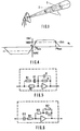
- Fig. 1 die keulenförmige, scharf gebündelte Strahlungscharakteristik eines Folgeradars mit Verfolgungsvolumen,
- Fig. 2 ein Blockdiagramm eines Folgeradars mit Distanzverfolgung mittels halbiertem Distanztor und Quadraturkanal, wobei die Winkelverfolgungsstromkreise nicht eingezeichnet sind,
- Fig. 3 eine Kompensationseinrichtung KE für Wetterechos,
- Fig. 4 die ideale Charakteristik eines Frequenzdiskriminators FDK,
- Fig. 5 ein Beispiel eines verzögernden Aktivfilters zweiter Ordnung,
- Fig. 6 ein Beispiel eines differenzierenden Aktivfilters zweiter Ordnung,
- Fig. 7 bis 12 verschiedene Modulationsschaltungen für das Referenzsignal, darunter
- Fig. 7 einen Analogmodulator für einen Proportionalregler,
- Fig. 8 einen Analogmodulator für einen Integralregler,
- Fig. 9 einen Digitalmodulator für einen Proportionalregler,
- Fig. 10 einen Digitalmodulator für einen Integralregler,
wobei bei den Modulationsschaltungen gemäss - Fig. 9 und Fig. 10 der Modulationstakt von der Pulswiederholungsfrequenz abhängt, also PRFsynchron ist,
- Fig. 11 einen Digitalmodulatorfüreinen Proportionalregler,
- Fig. 12 einen Digitalmodulator für einen Integralregler, wobei bei den Modulationsschaltungen gemäss Fig. 11 und Fig. 12 der Modulationstakt freilaufend ist und
- Fig. 13 ein Blockdiagramm eines Monopulsradars mit Quadraturkanal, wobei die Stromkreise für Höhenwinkel und Distanzverfolgung weggelassen wurden.
- Gemäss Fig. 1 kann'das Radarvolumen 1 durch eine senkrecht zur Achse der Strahlungscharakteristik orientierte Ebene 2 distanzmässig in zwei Distanzvolumenhälften oder durch eine die Achse der Strahlungscharakteristik enthaltende Ebene 3 winkelmässig in zwei Winkelvolumenhälften halbiert werden, wobei im letzten Fall dem Seiten-und dem Höhenwinkel eine besondere Bedeutung zukommt.
- Die Dopplerfrequenz der bewegten Wetterechos wird im Radarvolumen des Folgeradars zusammen mit dem Zielecho, d.h. genau dort, wo die Wetterechos auch kompensiert werden sollen, gemessen. Die erfindungsgemässe Anordnung kann sowohl bei einer Distanzmess- als auch bei einer Winkelmesseinrichtung eingesetzt werden. Wesentlich für diese Anordnung ist lediglich, dass das Radarvolumen in zwei praktisch gleiche Hälften A und B aufgeteilt wird.
- Das in Fig. 2 dargestellte Impulsdoppler-Folgeradargerät weist eine Antenne ANT, eine Sende-/Empfangseinrichtung SEE, eine Distanzauswerteeinrichtung AWE und eine Kompensationseinrichtung für Wetterechos KE auf. Dabei ist in der Sende- /Empfangseinrichtung SEE ein mit der Antenne ANT verbundener Duplexermischer DM vorhanden, dessen Ausgangssignal über einen regulierbaren Zwischenfrequenzverstärker ZFV einerseits dem ersten Eingang eines Quadratur- Phasenamplituden-Detektors PDQ und andererseits dem ersten Eingang eines Inphasen-Amplituden-Detektors PDI zugeführt wird, wobei ein Referenzsignal aus einem zweiten Ausgang des Duplexermischers DM über einen Kohärenzoszillator COHO und über die Kompensationseinrichtung KE einerseits direkt zum zweiten Eingang des Inphasen-Amplituden-Detektors PDI und andererseits über einen 90°-Phasenschieber PS zum zweiten Eingang des Quadratur-Phasenamplituden-Detektors PDQ geführt ist. Dabei wird das Ausgangssignal des Quadratur-Phasenamplituden-Detektors PDQ einerseits über eine Boxcarschaltung THAO für die erste Torhälfte dem ersten Eingang eines Quadratur-Addierverstärkers AVO und andererseits über eine Boxcarschaltung THBO für die zweite Torhälfte dem ersten Eingang eines Quadraturdifferenzverstärkers DVQ zugeführt, wobei der Ausgang der Boxcarschaltung THAO mit dem zweiten Eingang des Differenzverstärkers DVO und der Ausgang der Boxcarschaltung THBQ mit dem zweiten Eingang des Addierverstärkers AVQ verbunden ist. Das Ausgangssignal Uq des Addierverstärkers AVQ ist gegebenenfalls über ein Tiefpassfilter dem ersten Eingang der Auswerteeinrichtung AWE und einem weiteren Eingang der Kompensationseinrichtung KE und das Ausgangssignal Vq des Differenzverstärkers DVQ gegebenenfalls über ein zweites Tiefpassfilter dem zweiten Eingang der Auswerteeinrichtung AWE und dem dritten Eingang der Kompensationseinrichtung KE zugeführt. Ausserdem ist der Duplexermischer DM wie üblich mit einem Sender SD und mit einem stabilen Lokaloszillator STALO verbunden.
- Das Ausgangssignal des Inphasen-Amplituden-Detektors PDI wird ebenfalls einerseits über eine Boxcarschaltung THAI für die erste Torhälfte dem ersten Eingang eines Inphasenaddierverstärkers AVI und andererseits über eine Boxcarschaltung TH BI für die zweite Torhälfte dem ersten Eingang eines Inphasendifferenzverstärkers DVI zugeführt, wobei der Ausgang der Boxcarschaltung THAI mit dem zweiten Eingang des Differenzverstärkers DVI und der Ausgang der Boxcarschaltung THBI mit dem zweiten Eingang des Addierverstärkers AVI verbunden ist. Das Ausgangssignal Ui des Addierverstärkers AVI ist gegebenenfalls über ein Tiefpassfilter dem dritten Eingang der Auswerteeinrichtung AWE und dem vierten Eingang der Kompensationseinrichtung KE und das Ausgangssignal Vi des Differenzverstärkers DVI gegebenenfalls über ein weiteres Tiefpassfilter dem vierten Eingang der Auswerteeinrichtung AWE und dem fünften Eingang der Kompensationseinrichtung KE zugeführt.
- In der Sende-/Empfangseinrichtung SEE ist der Zwischenfrequenzverstärker ZFV durch eine einen Amplitudendetektor, eine Summentor- und eine Boxcarschaltung aufweisende Regelschaltung RS geregelt.
- Zur Ausschaltung der Kompensationseinrichtung KE kann der Ausgang des Kohärenzoszillators COHO direkt mit dem Referenzeingang der Sende-/Empfangseinrichtung SEE, d.h. mit dem Eingang des Phasenschiebers PS und des Inphasen-Amplituden-Detektors PDI verbunden werden.
- In der Auswerteeinrichtung AWE sind zwei Quadrierschaltungen QQS und IQS sowie vier je mit einem der Signale Uq, Vq, Ui bzw. Vi beaufschlagte Dopplerfilterschaltungen DAO, DDO, DAI und DDI und eine ein Distanz-Fehlerspannungssignal Sf liefernde Addierschaltung FAS vorhanden, deren erster Eingang mit dem Ausgang einer die Ausgangssignale der Dopplerfilterschaltungen DAI und DDI multiplizierenden Inphasen-Multiplizierschaltung IMS und deren zweiter Eingang mit dem Ausgang einer die Ausgangssignale der Dopplerfilterschaltungen DAO und DDO multiplizierenden Quadraturmultiplizierschaltung QMS verbunden ist. Ausserdem wird das Ausgangssignal der Dopplerfilterschaltung DAI über die Quadrierschaltung IQS dem ersten Eingang einer Addierschaltung WAS und das Ausgangssignal der Dopplerfilterschaltung DAQ über die Quadrierschaltung QQS dem zweiten Eingang der Addierschaltung WAS zugeführt, deren Ausgang mit je einem Regeleingang der Dopplerfilterschaltungen DAQ, DDQ, DAI und DDI verbunden ist.
- Fig. 3 zeigt den Aufbau einer Kompensationseinrichtung KE mit einem Subtrahierer STH, der eingangsseitig einerseits über die Reihenschaltung eines Quadraturmultiplizierers OMZ, eines Quadraturaddierers QA, eines Qudaraturfilters OF und eines Quadraturmultiplikators OMK und andererseits über die Reihenschaltung eines Inphasenmultiplizierers IMZ, eines Inphasenaddierers IA, eines Inphasenfilters IF und eines Inphasenmultiplikators IMK mit dem Fehlerspannungssignal Sf beaufschlagt ist. Dabei ist der Ausgang des Inphasenaddierers IA mit dem zweiten Eingang des Quadraturmultiplikators OMK und der Ausgang des Ouadraturaddiers QA mit dem zweiten Eingang des Inphasenmultiplikators IMK verbunden. Der zweite Eingang des Quadraturaddierers QA ist mit dem Eingangssignal Vq und der zweite Eingang des Inphasenaddierers IA ist mit dem Eingangssignal Vi beaufschlagt. Der zweite Eingang des Ouadraturmultiplizierers OMZ ist mit dem Eingangssignal Uq und der zweite Eingang des Inphasenmultiplizierers IMZ ist mit dem Eingangssignal Ui beaufschlagt. Der Ausgang des Subtrahierers STH ist über ein Tiefpassfilter TPF mit dem Steuereingang des Modulators MD verbunden, dessen Ausgangssignal Sm dem Referenzeingang der Sende-/Empfangseinrichtung SEE zugeführt wird. Der andere Eingang des Modulators MD ist mit dem Ausgangssignal Sc des Kohärenzoszillators COHO beaufschlagt, wobei der Modulator MD beispielsweise ein Einseitenband-oder ein Phasenmodulator sein kann.
- Die Schaltungsanordnung nach den Figuren 2 und 3 funktioniert nun folgendermassen: Ein von der Antenne ANT empfangenes Ziel und Echosignal wird von der Sende-/Empfangseinrichtung SEE und der Distanzauswerteeinrichtung AWE in bekannter Weise verarbeitet. Dabei sind zur Vereinfachung der Figuren nur die Signale angegeben, die einer Distanzauswertung entsprechen, obwohl das erfindungsgemässe Verfahren sowohl in einer Distanzmesseinrichtung als auch in einer Winkelmesseinrichtung Anwendung finden kann.
- Es wird zunächst der Fall betrachtet, bei dem nur Echosignale des zu verfolgenden Flugkörpers (Ziel), jedoch keine Wetterechosignale empfangen werden. Am ersten Ausgang der Sende-/Empfangseinrichtung SEE erscheint demnach ein Summensignal


- Die Elimination der Bewegungskomponente des Zieles durch Subtraktion der Signale der beiden Radarvolumenhälften A und B beruht auf der Annahme, dass das Ziel im Radarvolumen in der Antennenkeule zentriert ist. Beim Auftreten eines Schleppfehlers, d.h. wenn sich das Ziel nicht im Zentrum des Radarvolumens befindet, ist diese Annahme nicht mehr erfüllt und bei der Subtraktion der Signale aus den beiden Volumenhälften A und B bleibt ein Rest des Zielsignales übrig. Dies ist unerwünscht und kann dadurch behoben werden, dass zu der obenerwähnten Differenz noch ein gewichteter und mit Vorzeichen behafteter Anteil der Summe der Signale aus den beiden Volumenhälften addiert wird.
- Das im Quadraturmultiplizierer QMZ (Fig. 3) mit dem Distanzfehler-Spannungssignal Sf als Gewichtspannung multiplizierte Summensignal Uq = Uzq wird daher im Quadraturaddierer QA zum Differenzsignal Vq - εq·Uzq addiert, der dann als Resultat ein Zielsignal


- Es wird nun der Fall betrachtet, in dem nur ein Wetterechosignal vorhanden ist. Nimmt man in den beiden Volumenhälften A und B im Mittel gleich starke, nicht korrelierte Wetterechosignale (Clutter) an, so sind auch deren Summe Uq = Ucq und Differenz Vq = Vcq untereinander nicht korreliert und im Mittel gleich stark. Nach der Gewichtung addieren sich die Leistungen und das Wetterechosignal Urc (c bedeutet Clutter) im Quadraturkanal wird:

- Der Wetterechoanteil nimmt also mit von Null verschiedener Gewichtung zu. Es besteht also keine Gefahr, dass der Wetterechoanteil ebenfalls eliminiert wird. Entsprechendes gilt für den Inphasenkanal. Es kann auch eine andere als die vom Radar gelieferte Fehlerspannung Sf als Mass für die Zielexzentrizität dienen.
- Am Ausgang des Quadraturaddierers QA und des Inphasenaddierers IA erscheint gemäss obiger Rechendarstellung je ein vom Zielecho befreites Signal Urcq bzw. Urci in der Reglerrückkopplungsschlaufe zur Kompensation der Wetterechos im Verfolgungstor, wobei die Signale Urci und Urcq sich in der Wetterechophase um 90° unterscheiden, d.h.,


- Das Ausgangssignal des Subtrahierers STH wird als Differenz von Produkten gebildet, welche je aus den Signalen Urci, Urcq und deren gefilterten Werten Urci' und Urcq' gebildet werden.
- Die Filter IF und OF haben gleichen Amplitudengang A(w) und gleichen Phasengang Φ (w), die von der komplexen Übertragungsfunktion G(w) bestimmt sind und auch als Real- R (w) und Imaginärkomponenten I(w) der Übertragungsfunktion definiert sind.
- Nach dem Filter I entsteht

- Für das Ausgangssignal des Filters QF gilt entsprechend

- In den Multiplikatoren OMK und IMK werden die Realteile der Eingangssignalewiefolgtmultipliziert:


- Bei gleichzeitigem Anliegen mehrerer Wetterechosignale verschiedener Frequenz wn und Amplitude Urcn weist das Ausgangssignal Ufn eine Gleichspannungskomponente auf, welche der Summe der gewogenen Leistungen der Einzelsignale entspricht.

- Zusätzlich entstehen noch Wechselspannungskomponenten, welche mit den Frequenzdifferenzen aus den Einzelsignalen auftreten. Diese werden durch das nachgeschaltete Tiefpassfilter TPF unterdrückt. Das Signal Ufn dient als Fehlersignal des Regelkreises zur Unterdrückung der Wetterechos in der Einrichtung AWE. Deshalb muss der Frequenzgang I(w) des Frequenzdiskriminators FDK gewissen Anforderungen genügen. Fig. 4 zeigt eine ideale Frequenzdiskriminatorcharakteristik mit einem linearen Verlauf von I (w) zwischen den Werten + Im(w) für + wmin und -Im(w) für -wmin, wobei die Spiegelung am Koordinatennullpunkt der schon erwähnten Vorzeichenumpolung durch den Wetterecho-geschwindigkeitsvektor entspricht. Für eine günstige Charakteristik müsste das Verhältnis wmax/wmin (Bandbreite) möglichst gross und die Welligkeit dazwischen möglichst klein sein. Im Bereich des Nullpunktes muss Linearität angestrebt werden. Filterschaltungen mit einer Filtercharakteristik für I (w) nach Fig. 4 können beispielsweise durch die Schaltungen nach Fig. 5 und 6 recht gut angenähert realisiert werden. Es genügen jedoch auch einfache Hoch- oder Tiefpassfilter erster Ordnung.
- Im Frequenzdiskriminator FDK können die Filter QF und IF unter sich gleich sein und beispielsweise eine leicht realisierbare Übertragungsfunktion nach den Formeln


- Solche Filter, deren Frequenzverlauf des Imaginärteils bei tiefen Frequenzen proportional zur Frequenz ist, sind mit RC-Gliedern einfach zu realisieren.
- Bei erhöhten Anforderungen an die Bandbreite nimmt man einfache Filter höherer Ordnung. Fig. 5 zeigt eine mögliche Realisierung eines Filters nach der Formel

- Fig. 6 zeigt eine mögliche Realisierung eines Filters nach der Formel

- Zur automatischen Kompensation der bewegten Wetterechos muss ein den Zustand Ufn = 0 suchender Regelkreis zwischen dem Fehlerspannungssignal Ufn und dem Referenzsignal am Eingang der Sende-/Empfangseinrichtung SEE über eine Modulationsschaltung geschlossen werden. Beinhaltet eine solche Modulationsschaltung MD einen Einseitenbandmodulator, so gibt sie ein Ausgangssignal ab, dessen Frequenz der Summe der Frequenz wref beispielsweise des COHO-Signals bei empfangskohärenten Radarsystemen bzw. des Referenzsignals bei vollkohärenten Systemen und der Frequenz wck eines vom Fehlerspannungssignal Ufn abhängigen Kompensationssignals entspricht. Da die Auswertefrequenz der Ausgangssignale der Phasenamplitudendetektoren PDQ und PDI (Fig. 2) der Differenz der Frequenzen von deren Eingangssignalen entspricht, wird die Frequenz wck des Kompensationssignals derart geregelt, dass die Frequenz wck möglichst gleich wie die Frequenz wc wird. Damit ist das Wetterechodopplersignal in einen so tiefen Frequenzbereich verschoben, dass es von den Dopplerfiltern unterdrückt wird. Aber auch die Dopplerfrequenz des Zielsignals wird um denselben Betrag verschoben und muss deshalb nach Bedarf bei der Pulswiederholungsfrequenz-Steuerung berücksichtigt werden, um Blindgeschwindigkeiten zu vermeiden. Da die Arbeitsweise der Distanzauswerteeinrichtung AWE nach Fig. 2 an sich bekannt ist, braucht sie hier nicht näher beschrieben zu werden.
- Für die Realiserung des Modulators MD beispielsweise als Einseitenbandmodulator sind eine Reihe von Möglichkeiten denkbar. Sie unterscheiden sich durch die Anwendung einer Proportional- oder einer Integralregelung, beide in Analog- oder Digitaltechnik. Bei Digitaltechnik kann ausserdem der Modulationstakt pulswiederholungsfrequenzsynchron (PRF) oder frei gewählt werden. Die daraus entstehenden sechs Kombinationsmöglichkeiten sind in den Fig. 7 bis 12 in Blockschaltbildern festgehalten. In diesen Figuren stellen CT1 und CT2 Zähler, X einen digitalen Multiplikator, A/D einen Analog-/DigitalWandler, PLLM einen PLL-Modulator, DPM einen digitalen Phasenmodulator und VCO einen spannungsgesteuerten Oszillator dar. Da diese Methoden bekannt sind, werden sie hier nicht näher beschrieben.
- In Fig. 13 ist die zur Seitenwinkelverfolgung dienende Teilschaltung eines Monopulsfolgeradars mit Quadraturkanal dargestellt. Diese Anordnung weist eine Antenne AN und eine Sende-/Empfangseinrichtung SE sowie eine Auswerteeinrichtung AWE und eine Kompensationseinrichtung KE der bereits beschriebenen Art auf. In der Sende-/Empfangseinrichtung SE ist ein Duplexermischer DU vorhanden, der über je einen Eingang mit einem Sender SEN und einem stabilen Lokaloszillator STALO und über geeignete Ausgänge mit einem Kohärenzoszillator COHO, einem Komparator KP und je einem Zwischenfrequenzverstärker V1 und V2 verbunden ist. Der Komparator KP ist in bekannter Weise mit der Antenne AN verbunden.
- Das Ausgangssignal Sm der Kompensationseinrichtung KE wird direkt den Modulationseingängen von zwei Phasenamplitudendetektoren PD1 und PD2 und über einen 90°-Phasenschieber PH den Modulationseingängen von zwei weiteren Phasenamplitudendetektoren PD3 und PD4 zugeführt. Dabei sind die Signaleingänge der Phasenamplitudendetektoren PD1 und PD3 mit dem Ausgang des Zwischenfrequenzverstärkers V1 und die Signaleingänge der Phasenamplitudendetektoren PD2 und PD4 mit dem Ausgang des Zwischenfrequenzverstärkers V2 verbunden; mit diesem Ausgang ist ausserdem der Eingang einer Regelschaltung RG verbunden, die einen Amplitudendemodulator, ein Summentor und eine Boxcarschaltung umfasst. Das Ausgangssignal der Regelschaltung RG dient zur Regelung der Zwischenfrequenzverstärker V1 und V2. Die Ausgänge der Phasenamplitudendetektoren PD1, PD2, PD3 und PD4 sind über je ein Tiefpassfilter TP1, TP2, TP3 und TP4 mit je einem Eingang der Auswerteeinrichtung AWE verbunden. Bei Fig. 2 erfolgt die Differenzbildung zwischen den Volumenhälften in den Differenzbildeschaltungen DVO und DVI, während sie bei Fig. 13 bereits im Komparator KP gebildet wird.
Claims (4)
Applications Claiming Priority (2)
| Application Number | Priority Date | Filing Date | Title |
|---|---|---|---|
| CH1093/79 | 1979-02-05 | ||
| CH109379A CH645467A5 (de) | 1979-02-05 | 1979-02-05 | Anordnung zur unterdrueckung von wetterechos in einem impulsdoppler-folge-radargeraet. |
Publications (2)
| Publication Number | Publication Date |
|---|---|
| EP0014242A1 EP0014242A1 (de) | 1980-08-20 |
| EP0014242B1 true EP0014242B1 (de) | 1982-05-05 |
Family
ID=4202307
Family Applications (1)
| Application Number | Title | Priority Date | Filing Date |
|---|---|---|---|
| EP79104826A Expired EP0014242B1 (de) | 1979-02-05 | 1979-12-01 | Anordnung zur Unterdrückung von Wetterechos in einem Impulsdoppler-Folge-Radargerät |
Country Status (4)
| Country | Link |
|---|---|
| US (1) | US4430654A (de) |
| EP (1) | EP0014242B1 (de) |
| CH (1) | CH645467A5 (de) |
| DE (1) | DE2962741D1 (de) |
Families Citing this family (23)
| Publication number | Priority date | Publication date | Assignee | Title |
|---|---|---|---|---|
| US5418536A (en) * | 1981-12-21 | 1995-05-23 | Westinghouse Electric Corporation | Bandwidth and amplitude insensitive frequency discriminator |
| DE3837348A1 (de) * | 1988-11-03 | 1990-05-10 | Diehl Gmbh & Co | Radarempfaenger |
| US6674397B2 (en) * | 2002-05-13 | 2004-01-06 | Honeywell International Inc. | Methods and apparatus for minimum computation phase demodulation |
| US7808422B1 (en) | 2003-07-31 | 2010-10-05 | Rockwell Collins, Inc. | Predictive and adaptive weather radar detection system and method |
| US8902100B1 (en) | 2008-03-07 | 2014-12-02 | Rockwell Collins, Inc. | System and method for turbulence detection |
| US8203480B1 (en) | 2003-07-31 | 2012-06-19 | Rockwell Collins, Inc. | Predictive and adaptive weather radar detection system and method |
| US9846230B1 (en) | 2013-03-15 | 2017-12-19 | Rockwell Collins, Inc. | System and method for ice detection |
| US9057773B1 (en) | 2012-12-06 | 2015-06-16 | Rockwell Collins, Inc. | Weather information display system and method |
| US9244167B1 (en) | 2008-03-07 | 2016-01-26 | Rockwell Collins, Inc. | Long range weather information display system and method |
| US9864055B1 (en) | 2014-03-12 | 2018-01-09 | Rockwell Collins, Inc. | Weather radar system and method for detecting a high altitude crystal cloud condition |
| US9244166B1 (en) | 2008-03-07 | 2016-01-26 | Rockwell Collins, Inc. | System and method for ice detection |
| US9244157B1 (en) | 2008-03-07 | 2016-01-26 | Rockwell Collins, Inc. | Weather radar threat depiction system and method |
| US9223020B1 (en) | 2010-09-28 | 2015-12-29 | Rockwell Collins, Inc. | System and method for weather detection using more than one source of radar data |
| US9019146B1 (en) | 2011-09-27 | 2015-04-28 | Rockwell Collins, Inc. | Aviation display depiction of weather threats |
| US9823347B1 (en) | 2014-03-12 | 2017-11-21 | Rockwell Collins, Inc. | Weather radar system and method for high altitude crystal warning interface |
| US9116244B1 (en) | 2013-02-28 | 2015-08-25 | Rockwell Collins, Inc. | System for and method of weather phenomenon detection using multiple beams |
| US9535158B1 (en) | 2013-11-21 | 2017-01-03 | Rockwell Collins, Inc. | Weather radar system and method with fusion of multiple weather information sources |
| US9599707B1 (en) | 2014-01-23 | 2017-03-21 | Rockwell Collins, Inc. | Weather radar system and method with path attenuation shadowing |
| US9810770B1 (en) | 2014-07-03 | 2017-11-07 | Rockwell Collins, Inc. | Efficient retrieval of aviation data and weather over low bandwidth links |
| US9869766B1 (en) | 2015-01-28 | 2018-01-16 | Rockwell Collins, Inc. | Enhancement of airborne weather radar performance using external weather data |
| US10809375B1 (en) | 2015-09-14 | 2020-10-20 | Rockwell Collins, Inc. | Radar system and method for detecting hazards associated with particles or bodies |
| US10302815B1 (en) | 2015-10-01 | 2019-05-28 | Rockwell Collins, Inc. | System and method of integrating global convective weather |
| US10494108B1 (en) | 2016-05-17 | 2019-12-03 | Rockwell Collins, Inc. | System and method for providing icing condition warnings |
Family Cites Families (7)
| Publication number | Priority date | Publication date | Assignee | Title |
|---|---|---|---|---|
| US3522604A (en) * | 1955-12-09 | 1970-08-04 | Hughes Aircraft Co | Coherent-angle tracking system |
| US3707718A (en) * | 1969-02-18 | 1972-12-26 | Westinghouse Electric Corp | Radar system |
| US3742500A (en) * | 1970-08-24 | 1973-06-26 | Raytheon Co | Mti radar |
| US4062011A (en) * | 1972-08-21 | 1977-12-06 | Control Data Corporation | MTI System processor and method |
| US4093949A (en) * | 1976-05-26 | 1978-06-06 | Hughes Aircraft Company | Clutter tracker using a smoothed doppler frequency measurement |
| US4117538A (en) | 1977-05-04 | 1978-09-26 | Raytheon Company | Radar system with specialized weighting |
| CH629898A5 (de) | 1978-02-09 | 1982-05-14 | Siemens Ag Albis | Anordnung zur verbesserung der winkelvermessung bei einem folgeradar. |
-
1979
- 1979-02-05 CH CH109379A patent/CH645467A5/de not_active IP Right Cessation
- 1979-12-01 EP EP79104826A patent/EP0014242B1/de not_active Expired
- 1979-12-01 DE DE7979104826T patent/DE2962741D1/de not_active Expired
-
1982
- 1982-06-28 US US06/392,624 patent/US4430654A/en not_active Expired - Fee Related
Also Published As
| Publication number | Publication date |
|---|---|
| EP0014242A1 (de) | 1980-08-20 |
| CH645467A5 (de) | 1984-09-28 |
| DE2962741D1 (en) | 1982-06-24 |
| US4430654A (en) | 1984-02-07 |
Similar Documents
| Publication | Publication Date | Title |
|---|---|---|
| EP0014242B1 (de) | Anordnung zur Unterdrückung von Wetterechos in einem Impulsdoppler-Folge-Radargerät | |
| DE102007061912B4 (de) | Pulsradar, fahrzeugmontiertes Radar und Ladungsunterstützungsradar | |
| DE2544406C2 (de) | Radargerät, bei welchem zur Korrektur von Störschwankungen in zueinander parallelen Kanälen diesen in periodischen Zeitabständen ein Testsignal aufgeprägt wird | |
| DE3038961C2 (de) | ||
| DE2259332C2 (de) | Schaltungsanordnung zur Festzeichenunterdrückung bei einem eine fliegende Plattform aufweisenden Impuls-Dopplerradarsystem | |
| DE19512904C2 (de) | Verfahren zur Bestimmung der Zwischenfrequenzenabweichung bei Frequenz-Puls-Radarsystemen | |
| DE1237187B (de) | Impulsradarempfaenger mit zwei Kanaelen zur Beseitigung von unerwuenschten Empfangssignalen | |
| DE2439044A1 (de) | Radareinrichtung | |
| DE1591312A1 (de) | Impulsverfahren zur Richtungsfindung | |
| DE3321263A1 (de) | Puls-doppler-radargeraet mit veraenderbarer pulsfolgefrequenz | |
| DE2133395B2 (de) | Einrichtung zur Kompensation deer Eigenbewegung einer kohärenten Impuls-Doppler-Radaranlage | |
| DE3041459C2 (de) | ||
| EP0078872B1 (de) | Anordnung zur Kompensation der Eigenbewegtechos eines Radargerätes | |
| DE68917502T2 (de) | Echokompensator für Echosignale mit veränderlicher Phase. | |
| DE2741847A1 (de) | Einrichtung zum feststellen des vorhandenseins von radarechos und damit ausgeruestetes impulsradarsystem | |
| EP0114196B1 (de) | Folgeradar | |
| DE4233677C2 (de) | Verfahren zum Korrelationsempfang von vorbekannten periodisch ausgesendeten Impulsen und Vorrichtung zur Durchführung des Verfahrens sowie Verwendung derselben | |
| DE3222489A1 (de) | Puls-doppler-radargeraet mit einem pulslaengen-diskriminator | |
| DE1591319B1 (de) | Bordradarempfaenger fuer bewegte Ziele mit Monopuls-Summen- und Diffierenzkanaelen zur Azimut- und Elevationsrichtungsverfolgung | |
| DE2726700C2 (de) | System zur Unterdrückung von unerwünschten Echos bei einem Impulsradar | |
| DE2428379C3 (de) | Schaltungsanordnung zur Unterdruckung von Wetterechos in einem Zielverfolgungs-Impuls-Doppler-Radargerät | |
| DE977950C (de) | ||
| DE4122108A1 (de) | Pulsdopplerradar | |
| DE2641689C2 (de) | Pulsradargerät mit Einrichtungen zur Integration der Empfangssignale | |
| DE1961880C3 (de) | Puls-Doppler-Radarempfänger mit einer Vielzahl von Entfernungskanälen veränderbaren Frequenzgangs zum Unterdrücken unerwünschter Echos |
Legal Events
| Date | Code | Title | Description |
|---|---|---|---|
| PUAI | Public reference made under article 153(3) epc to a published international application that has entered the european phase |
Free format text: ORIGINAL CODE: 0009012 |
|
| 17P | Request for examination filed | ||
| AK | Designated contracting states |
Designated state(s): BE DE FR GB IT NL |
|
| ITF | It: translation for a ep patent filed | ||
| GRAA | (expected) grant |
Free format text: ORIGINAL CODE: 0009210 |
|
| AK | Designated contracting states |
Designated state(s): BE DE FR GB IT NL |
|
| REF | Corresponds to: |
Ref document number: 2962741 Country of ref document: DE Date of ref document: 19820624 |
|
| PGFP | Annual fee paid to national office [announced via postgrant information from national office to epo] |
Ref country code: FR Payment date: 19841220 Year of fee payment: 6 |
|
| PGFP | Annual fee paid to national office [announced via postgrant information from national office to epo] |
Ref country code: BE Payment date: 19841231 Year of fee payment: 6 |
|
| PGFP | Annual fee paid to national office [announced via postgrant information from national office to epo] |
Ref country code: NL Payment date: 19861231 Year of fee payment: 8 |
|
| PG25 | Lapsed in a contracting state [announced via postgrant information from national office to epo] |
Ref country code: BE Effective date: 19871231 |
|
| BERE | Be: lapsed |
Owner name: SIEMENS-ALBIS A.G. Effective date: 19871231 |
|
| PG25 | Lapsed in a contracting state [announced via postgrant information from national office to epo] |
Ref country code: NL Effective date: 19880701 |
|
| GBPC | Gb: european patent ceased through non-payment of renewal fee | ||
| NLV4 | Nl: lapsed or anulled due to non-payment of the annual fee | ||
| PG25 | Lapsed in a contracting state [announced via postgrant information from national office to epo] |
Ref country code: FR Free format text: LAPSE BECAUSE OF NON-PAYMENT OF DUE FEES Effective date: 19880831 |
|
| REG | Reference to a national code |
Ref country code: FR Ref legal event code: ST |
|
| PG25 | Lapsed in a contracting state [announced via postgrant information from national office to epo] |
Ref country code: GB Effective date: 19881118 |
|
| PGFP | Annual fee paid to national office [announced via postgrant information from national office to epo] |
Ref country code: DE Payment date: 19890411 Year of fee payment: 10 |
|
| PG25 | Lapsed in a contracting state [announced via postgrant information from national office to epo] |
Ref country code: DE Effective date: 19900901 |
|
| PLBE | No opposition filed within time limit |
Free format text: ORIGINAL CODE: 0009261 |
|
| STAA | Information on the status of an ep patent application or granted ep patent |
Free format text: STATUS: NO OPPOSITION FILED WITHIN TIME LIMIT |