EP0020092B1 - Dérailleur de bicyclette - Google Patents
Dérailleur de bicyclette Download PDFInfo
- Publication number
- EP0020092B1 EP0020092B1 EP80301694A EP80301694A EP0020092B1 EP 0020092 B1 EP0020092 B1 EP 0020092B1 EP 80301694 A EP80301694 A EP 80301694A EP 80301694 A EP80301694 A EP 80301694A EP 0020092 B1 EP0020092 B1 EP 0020092B1
- Authority
- EP
- European Patent Office
- Prior art keywords
- retainer
- movable
- members
- control
- spring
- Prior art date
- Legal status (The legal status is an assumption and is not a legal conclusion. Google has not performed a legal analysis and makes no representation as to the accuracy of the status listed.)
- Expired
Links
- 238000004146 energy storage Methods 0.000 claims description 31
- 230000000717 retained effect Effects 0.000 claims description 13
- 238000006073 displacement reaction Methods 0.000 claims description 6
- 230000002093 peripheral effect Effects 0.000 claims 1
- 238000010276 construction Methods 0.000 description 4
- 238000004519 manufacturing process Methods 0.000 description 2
- 230000004048 modification Effects 0.000 description 2
- 238000012986 modification Methods 0.000 description 2
- 238000000926 separation method Methods 0.000 description 2
Images


Classifications
-
- B—PERFORMING OPERATIONS; TRANSPORTING
- B62—LAND VEHICLES FOR TRAVELLING OTHERWISE THAN ON RAILS
- B62M—RIDER PROPULSION OF WHEELED VEHICLES OR SLEDGES; POWERED PROPULSION OF SLEDGES OR SINGLE-TRACK CYCLES; TRANSMISSIONS SPECIALLY ADAPTED FOR SUCH VEHICLES
- B62M9/00—Transmissions characterised by use of an endless chain, belt, or the like
- B62M9/04—Transmissions characterised by use of an endless chain, belt, or the like of changeable ratio
- B62M9/06—Transmissions characterised by use of an endless chain, belt, or the like of changeable ratio using a single chain, belt, or the like
- B62M9/10—Transmissions characterised by use of an endless chain, belt, or the like of changeable ratio using a single chain, belt, or the like involving different-sized wheels, e.g. rear sprocket chain wheels selectively engaged by the chain, belt, or the like
- B62M9/12—Transmissions characterised by use of an endless chain, belt, or the like of changeable ratio using a single chain, belt, or the like involving different-sized wheels, e.g. rear sprocket chain wheels selectively engaged by the chain, belt, or the like the chain, belt, or the like being laterally shiftable, e.g. using a rear derailleur
- B62M9/121—Rear derailleurs
- B62M9/124—Mechanisms for shifting laterally
- B62M9/1248—Mechanisms for shifting laterally characterised by the use of biasing means, e.g. springs; Arrangements thereof
-
- B—PERFORMING OPERATIONS; TRANSPORTING
- B62—LAND VEHICLES FOR TRAVELLING OTHERWISE THAN ON RAILS
- B62M—RIDER PROPULSION OF WHEELED VEHICLES OR SLEDGES; POWERED PROPULSION OF SLEDGES OR SINGLE-TRACK CYCLES; TRANSMISSIONS SPECIALLY ADAPTED FOR SUCH VEHICLES
- B62M9/00—Transmissions characterised by use of an endless chain, belt, or the like
- B62M9/04—Transmissions characterised by use of an endless chain, belt, or the like of changeable ratio
- B62M9/06—Transmissions characterised by use of an endless chain, belt, or the like of changeable ratio using a single chain, belt, or the like
- B62M9/10—Transmissions characterised by use of an endless chain, belt, or the like of changeable ratio using a single chain, belt, or the like involving different-sized wheels, e.g. rear sprocket chain wheels selectively engaged by the chain, belt, or the like
- B62M9/12—Transmissions characterised by use of an endless chain, belt, or the like of changeable ratio using a single chain, belt, or the like involving different-sized wheels, e.g. rear sprocket chain wheels selectively engaged by the chain, belt, or the like the chain, belt, or the like being laterally shiftable, e.g. using a rear derailleur
- B62M9/121—Rear derailleurs
- B62M9/124—Mechanisms for shifting laterally
- B62M9/1244—Mechanisms for shifting laterally limiting or positioning the movement
- B62M9/1246—Mechanisms for shifting laterally limiting or positioning the movement using cams or plates
-
- Y—GENERAL TAGGING OF NEW TECHNOLOGICAL DEVELOPMENTS; GENERAL TAGGING OF CROSS-SECTIONAL TECHNOLOGIES SPANNING OVER SEVERAL SECTIONS OF THE IPC; TECHNICAL SUBJECTS COVERED BY FORMER USPC CROSS-REFERENCE ART COLLECTIONS [XRACs] AND DIGESTS
- Y10—TECHNICAL SUBJECTS COVERED BY FORMER USPC
- Y10T—TECHNICAL SUBJECTS COVERED BY FORMER US CLASSIFICATION
- Y10T74/00—Machine element or mechanism
- Y10T74/20—Control lever and linkage systems
- Y10T74/20576—Elements
- Y10T74/20636—Detents
- Y10T74/20714—Lever carried rack
Definitions
- This invention relates to a multi-speed derailleur for a cycle, which comprises a fixing member, two link members and a movable member mounting a chain guide, and has a return spring disposed for acting between two of said members, so that with the aid of a control cable and the action of said return spring said movable member can be reciprocably moved relative to said fixing member for changing the cycle speed.
- the chain contacts relatively slowly a sprocket to which the chain is to be switched thereby generating noise and increasing wear of the chain and sprocket.
- the present invention provides a cycle derailleur, which comprises a fixing member, two link members and a movable member mounting a chain guide, and has a return spring disposed for acting between two of said members, so that with the aid of a control cable and the action of said return spring said movable member can be reciprocably moved relative to said fixing member to bring said chain guide into position corresponding to a desired speed change stage, a control member for positioning said movable member in any one of a plurality of predetermined positions, said control member being connected to one of said fixing, link and movable members and having a plurality of engagement portions corresponding to said predetermined positions which correspond in turn to different speed change stages, said engagement portions each having an engagement face for each speed change stage, said engagement faces being interconnected by connecting faces; a retainer engageable with any one of said engagement faces of said control member for retaining said movable member in a said predetermined position corresponding to a desired speed, said retainer being pivotally connected to another one of said fixing, link and movable members which other member is
- the mounting of the control element and retainer may be not only directly on two relatively movable members of the derailleur members (fixing member, two linkage members and movable member) but alternatively on pivot pins connecting these members or indirectly on the two members via a third member secured or pivotally connected thereto.
- the present invention is of course applicable to a front derailleur as well as to a rear derailleur.
- the derailleur of the invention may be used with a control cable comprising a control wire without an outer sheath as well as with a cable comprising an inner wire and an outer sheath, with one of the inner wire and outer sheath being supported to the retainer and the other to one of the four derailleur members.
- the derailleur of the present invention enables the movable member to be rapidly moved reciprocably by means of pulling of the control cable and the force of the return spring substantially independently of the speed of operation of the cable via the control lever, whereby noise generated from the drive chain guided by the chain guide resulting from contact with the sprockets, is minimized and whereby wear of the drive chain and sprockets is significantly reduced.
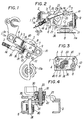
- the embodiments shown in the drawings are all rear derailleurs each of which has four principal members, namely, a fixing member 1, two parallel link members 5 and 6, and a movable member 9, and also a return spring 12.
- the fixing member 1 comprises a bracket 1a mountable, in use, with a hub shaft (not shown) to a rear fork end (not shown) of a cycle and a support body 1 b mounted on the bracket 1 a so as to be pivotable within a given angular range about a pivot shaft 2 mounted on the bracket 1 a, but non-movable in the direction of movement of the movable member 9.
- the support body 1 b is provided at one side thereof with opposed sidewalls carrying the two link members 5 and 6 pivotally connected thereto by means of two pivot pins 3 and 4.
- the link members 5 and 6 are each generally C- of U-shaped in section and arranged with their open sides opposite each other.
- the movable member 9 is similar in shape to the support body 1 b, has at one side opposed sidewalls, and is pivotally connected to the foremost ends of the link members 5 and 6 by means of pivot pins 7 and 8.
- a chain guide 11 having two guide pulleys 11 a is mounted so as to be rotatable within a given range about a pivot shaft 10 disposed parallel to the pivot shaft 2.
- the guide pulleys 11 a carry thereon a drive chain (not shown) and are movable axially of a multi-stage freewheel (not shown) to guide the chain to be switched to a desired sprocket on the freewheel for changing the cycle speed.
- the present invention has been so designed that the derailleur constructed as described above is provided on the two relatively movable members 1, 9 of the four principal derailleur members with a control member 20 having a plurality of engagement portions 21 corresponding to the number of speed change stages, a retainer 30 engageable with any one of the engagement portions 21 to resist displacement of the chain guide 11, an energy storage spring 40, and a tension spring 41 for maintaining a control wire 13 under tension, so that the chain guide 11, during speed changing, is positioned in accordance with a desired speed change stage and simultaneously retained in position, whilst when the retainer 30 is disengaged from the engagement portion 21 the chain guide 11 is free to be rapidly displaced to a position corresponding to another speed.
- the control member 20 and retainer 30 are mountable on the two relatively movable members in any one of the following arrangements: the control member 20 is mounted on the fixing member 1 and the retainer 30 on the movable member 9 or either of the link members 5 and 6; the control member 20 is mounted on the movable member 9 and the retainer 30 on the fixing member 1 or either of the link members 5 and 6; and the control member 20 is mounted on one of the link members 5 and 6 and the retainer 30 on the fixing member 1, movable member 9, or the other of the link members 5 and 6.
- control member 20 and retainer 30 could also be supported on the pivot pins 3, 4, 7 and 8, interconnecting the abovementioned four derailleur members, either directly or indirectly through separate members (not shown) attached to the four members 1, 5, 6, 9 or pins 3, 4, 7, 8.
- the control member 20 and retainer 30 could also be supported on the pivot pins 3, 4, 7 and 8, interconnecting the abovementioned four derailleur members, either directly or indirectly through separate members (not shown) attached to the four members 1, 5, 6, 9 or pins 3, 4, 7, 8.
- control member 20 is mounted on the movable member 9 and the retainer 30 on one link member 6, will now be described in detail with reference to Figs. 1 to 10.
- the control member 20 in this embodiment comprises a portion formed integrally with one sidewall of the.movable member 9 and extending therefrom toward the fixing member 1.
- the portion 20 has an aperture whose periphery is formed to provide six engagement portions 21 in the form of ratchet teeth.
- the engagement portions 21 have engagement faces 21 a for each retaining the retainer 30 in engagement therewith thereby to hold the chain guide 11 in a given position, and connecting faces 21 b extending between adjacent engagement faces.
- the engagement faces 21 a are arranged along a part-circular arc around a pin 33 to be further described below so that each corresponds to a different speed and has a length corresponding to the travel of the control lever (not shown) upon change from one speed to another.
- the retainer 30, as shown in Fig. 4, is generally in the form of a pawl engageable with each of the engagement portions 21, and pivotally mounted on a support arm 31 by means of a guide tube 32 and pin 33, the support arm 31 being pivotally connected to the link member 6 through a pin 34.
- the retainer 30 is operated by the control cable 13 which comprises an inner control wire 13a and an outer sheath 13b as shown.
- One of the inner wire 13a and outer sheath 13b may be supported on the retainer 30 and the other on the movable member 9, either of the link members 5 and 6, or either of the pivot pins 7 and 8 supporting the movable member 9.
- the outer sheath 13b is supported on the retainer 30 through a support 14 and the inner control wire 13 on the movable member 9 through a fixture 15.
- the energy storage spring 40 and tension spring 41 are interposed between the retainer 30 and the link member 6 carrying the retainer 30 via the support arm 31.
- the energy storage spring 40 is coiled about the pin 34 and retained at a first end to the pin 33 and at a second end to the pin 34.
- the tension spring 41 is coiled onto the guide tube 32 sleeved around the pin 33 and retained at one end to the pin 34 and at the other end to a projection extending from the retainer 30.
- the return spring 12 may be interposed between the fixing member 1 and the movable member 9 or either one of the link members 5 and 6; between the movable member 9 and either of the link members 5 and 6; or between the link members 5 and 6. In the drawings, the return spring 12 is shown interposed between the movable member 9 and the link member 6.
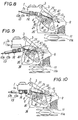
- the retainer 30 When the control cable 13 is displaced through a distance less than that required for changing from one speed to another, the retainer 30 is maintained in engagement with a given one of the engagement portions 21 thereby keeping the chain guide 11 stationary. When the cable 13 is, however, displaced through a distance greater than that required for changing from one speed to another the retainer 30 is disengaged from one of the engagement portions 21, enabling the return spring 12 or energy storage spring 40 to act on the chain guide 11 to rapidly move it to a desired speed change stage.
- the chain guide 11 is shown positioned for the highest speed stage.
- the control lever is operated to pull the control wire 13a to move the chain guide 11 from the position in Fig. 5 towards a position as shown in Fig. 7 corresponding to a low speed stage
- the retainer 30 and support arm 31 are subjected to a biasing force caused by movement of the outer sheath 13b relative to the control wire 13a, thereby reducing the separation between the support 14 and the fixture 15.
- the retainer 30 at first swings clockwise around the pin 33, at which point the tension spring 41 is resiliently deformed.
- the support arm 31 swings clockwise around the pin 34 through the swinging motion of the retainer 30, whereby the energy storage spring 40 is resiliently deformed to conserve therein the energy of the force transmitted through the control wire 13a.
- the energy storage spring 40 is simply resiliently deformed without disengagement of the retainer 30 from the engagement portion 21 with which it is engaged and the chain guide 11 is maintained stationary (with respect to lateral movement).
- the distance through which the control wire 13a is pulled is greater than said required amount the support arm 31 swings beyond a given angle, and the retainer 30 supported to the support arm 31 disengages from the engagement portion 21, thus adopting the condition shown in Fig. 6.
- the energy stored in the energy storage spring 40 immediately allows the chain guide 11 to move forward ⁇ rapidly.
- the retainer 30 together with the support arm 31 then swings counterclockwise around the pin 34 to engage with a successive engagement portion 21 to stop the forward: movement of chain guide 11.
- the rapid displacement of the chain guide 11 by the energy stored in the energy storage spring 40 can considerably reduce noise generated by contact of the chain with the sprocket during changing of speed.
- the retainer 30 moves in the same direction as each engagement face 21 a and along it, and after disengaging from the engagement face 21a, moves along each connecting face 21b.
- the movable member 9 is restrained from moving during movement of the retainer 30 along the engagement face 21a, and then allowed to move upon disengagement of the retainer 30 from the engagement face 21 a, thereby enabling the chain guide 11 to be rapidly displaced. Accordingly, the chain guide 11, which is rapidly displaced, can reduce noise generated by the chain during switching to a desired sprocket. Also, since the retainer 30 engages with one of the engagement portions 21 thereby to position the chain guide 11 for a desired speed change stage, the chain guide 11, even when the control cable 13a slightly varies in its displacement distance as required for changing speed, is stopped and retained in the correct position corresponding to any given speed change stage.
- the chain guide 11 moves rapidly by use only of the return spring 12 resiliently deformed by a pull of the control wire 13a, and without the energy storage spring 40.
- the tension spring 41 which always biases the retainer 30 so as to tend to tension the control wire 13a, allows the retainer 30 to swing counterclockwise for disengagement from one of the engagement portions 21 as shown in Fig. 9.
- the control wire 13a is slackened to an extent less than a certain amount, the movable member 9 remains stationary due to engagement of the retainer 30 with the engagement portion 21.
- the movable member 9 Upon disengagement of the retainer 30 therefrom, though, the movable member 9 is released so that the energy stored in the return spring 12 can rapidly return the chain guide 11, at which point the retainer 30, which is biased counterclockwise by the tension spring 41, automatically engages with the next engagem'ent portion 21 and is retained thereat due to rapid repositioning of the chain guide 11 immediately after disengagement of the retainer 30.
- the rapid repositioning of the chain guide 11 substantially reduces the noise generated by the chain in contact with a sprocket While it is being switched thereto.
- the noise is considerably reduced due to the fact that the retainer 30 moves along each engagement face 21a and parallel thereto, the movable member 9 is held against movement during the movement of the retainer 30 along the engagement face 21 a, and the disengagement of the retainer 30 from the engagement portion 21 moves the movable member 9 by use of the energy conserved in the return spring 12, so that the chain guide 11 may rapidly return.
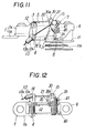
- the deraille shown in Figs. 11 to 20 each have the control member 20 mounted on the fixing member 1 and the retainer 30 mounted on the movable member 9, the inner control wire 13a being secured to the retainer 30 and the outer sheath 13b therefor being secured to the fixing member 1.
- These modified embodiments of Figs. 11 to 20 are basically similar in construction to the embodiment shown in Figs. 1 to 10, in which like members are represented by like reference numerals.
- engagement portions 21 on the control member 20 extend perpendicularly therefrom and a projection 30a engageable with each of the engagement portions 21 extends from the retainer 30.
- the retainer 30 is pivotally connected to the movable member 9 through a support pin 35.
- An energy storage spring 40 and a tension spring 41 are wound onto the support pin 35, the energy storage spring 40 being retained at a first end to the retainer 30 and at a second end to one axial end of a pivot pin 7, connecting the movable member 9 to a like member 5 so that the energy storage spring 40 is not resiliently deformed by the clockwise movement of retainer 30, in other words, in the working direction of the tension spring 41.
- the tension spring 41 is retained at one end to the retainer 30 and at its other end to said pivot pin 7, so that the energy storage spring 40 does not act when the tension spring 41 acts.
- the retainer 30 swings counterclockwise to store in the energy storage spring 40 the energy transmitted via the control wire 13a.
- the energy stored in the spring 40 allows the chain guide 11 to move forward rapidly, and the retainer 30, as shown in Fig. 14, then engages with the next engagement portion 21 thereby to stop the forward movement of chain guide 11.
- the control wire 13a is slackened in a position as shown in Fig.
- the retainer 30 is subjected to the force of the tension spring 41 and swings clockwise to disengage from the engagement portion 21, into a position as shown in Fig. 15. In this position, the energy stored in the return spring 12 allows the chain guide 11 to return in a rapid movement whereupon the retainer 30 engages with an adjacent engagement portion 21 to bring the chain guide 11 to a halt.
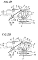
- a pivot pin 8 is extended axially for pivotally supporting the support arm 31
- a support pin 36 is mounted on the pin 8 so as to extend perpendicularly thereto and pivotally supports the retainer 30.
- An energy storage spring 40 is wound onto the support pin 36 and retained at a first end to the retainer 30 and at a second end to the support arm 31.
- the tension spring 41 is wound onto the pivot pin 8 and retained at one end to the support arm 31 and at its other end to the pin 7.
- the energy storage spring 40 and tension spring 41 are arranged so as to operate independently of each other and differ in their biasing direction so that the energy storage spring 40 does not act in the biasing direction of the tension spring 41.
- the retainer engages with the engagement portions of the control member to stop reciprocal movement of the chain guide for gear changing.
- the retainer is maintained in engagement with the engagement portions to prevent such reciprocal movement of the chain guide when the control cable is displaced by less than the required amount but disengages from the engagement portions when the control cable displacement is greater than or equal to the required amount to allow the energy storage spring or return spring to rapidly displace the chain guide.
- the chain guide can be accurately and correctly positioned with respect to each sprocket and be reliably retained in position. Also noise generated by the drive chain contacting with the sprockets during shifting of the chain guide, can be eliminated regardless of the speed of operation of the control cable and drive chain and sprocket wear reduced.
Landscapes
- Engineering & Computer Science (AREA)
- Chemical & Material Sciences (AREA)
- Combustion & Propulsion (AREA)
- Transportation (AREA)
- Mechanical Engineering (AREA)
- Devices For Conveying Motion By Means Of Endless Flexible Members (AREA)
- Flexible Shafts (AREA)
Claims (16)
Applications Claiming Priority (4)
| Application Number | Priority Date | Filing Date | Title |
|---|---|---|---|
| JP6534579A JPS5857346B2 (ja) | 1979-05-24 | 1979-05-24 | 自転車用デイレ−ラ− |
| JP65346/79 | 1979-05-24 | ||
| JP6534679A JPS5857347B2 (ja) | 1979-05-24 | 1979-05-24 | 自転車用デイレ−ラ− |
| JP65345/79 | 1979-05-24 |
Publications (3)
| Publication Number | Publication Date |
|---|---|
| EP0020092A2 EP0020092A2 (fr) | 1980-12-10 |
| EP0020092A3 EP0020092A3 (en) | 1981-05-06 |
| EP0020092B1 true EP0020092B1 (fr) | 1983-05-11 |
Family
ID=26406486
Family Applications (1)
| Application Number | Title | Priority Date | Filing Date |
|---|---|---|---|
| EP80301694A Expired EP0020092B1 (fr) | 1979-05-24 | 1980-05-22 | Dérailleur de bicyclette |
Country Status (3)
| Country | Link |
|---|---|
| US (1) | US4322209A (fr) |
| EP (1) | EP0020092B1 (fr) |
| DE (1) | DE3063075D1 (fr) |
Families Citing this family (18)
| Publication number | Priority date | Publication date | Assignee | Title |
|---|---|---|---|---|
| JPS6015516B2 (ja) * | 1979-12-19 | 1985-04-19 | 株式会社シマノ | 自転車用デイレ−ラ− |
| FR2496587B1 (fr) * | 1980-12-23 | 1986-02-28 | Bridgestone Cycle Co | Changement de vitesses pour bicyclette |
| FR2508862A1 (fr) * | 1981-07-03 | 1983-01-07 | Simplex Ets | Dispositif de commande assurant des positions multiples preetablies et controlees, applicable en particulier aux changements de vitesse pour les cycles et vehicules similaires |
| NL189286C (nl) * | 1981-07-08 | 1993-03-01 | Bridgestone Cycle Co | Versnellingsdrijfwerk voor een rijwiel. |
| US4507101A (en) * | 1982-04-07 | 1985-03-26 | Shimano Industrial Company Limited | Speed control device for a bicycle |
| US4530677A (en) * | 1983-02-22 | 1985-07-23 | Shimano Industrial Company Limited | Derailleur for a bicycle |
| DE3334455A1 (de) * | 1983-03-04 | 1984-09-06 | Bayer Ag, 5090 Leverkusen | Guanidin - derivate |
| USD307735S (en) | 1987-05-04 | 1990-05-08 | Bike-O-Matic Ltd. | Derailleur shifter |
| IT1211288B (it) * | 1987-09-04 | 1989-10-12 | Campagnolo Spa | Deragliatore posteriore per un cambio di velocita di biciclette |
| USD319206S (en) | 1988-08-03 | 1991-08-20 | Simplex SA (Ltd.) | Rear gear shift for bicycles and similar vehicles |
| JP2607328Y2 (ja) * | 1993-11-12 | 2001-07-09 | 株式会社シマノ | 自転車用リヤディレーラ |
| USD406084S (en) * | 1997-07-23 | 1999-02-23 | Shimano Inc. | Rear derailleur pulley set |
| US20080272253A1 (en) * | 2007-05-03 | 2008-11-06 | Peng-Yu Tseng | Derailleurbracket for a bicycle |
| US8678963B2 (en) * | 2011-09-21 | 2014-03-25 | Shimano Inc. | Bicycle front derailleur |
| US9651138B2 (en) | 2011-09-30 | 2017-05-16 | Mtd Products Inc. | Speed control assembly for a self-propelled walk-behind lawn mower |
| US10882587B2 (en) | 2017-06-26 | 2021-01-05 | Sram, Llc | Damper for a bicycle component |
| DE102018214218A1 (de) * | 2018-08-22 | 2020-02-27 | Sram Deutschland Gmbh | Hinterrad-Kettenschaltwerk mit exzentrischer Seilzug-Umlenkrollenanordung mit Übersetzungsverhältnis |
| US11661141B2 (en) * | 2019-11-27 | 2023-05-30 | Shimano Inc. | Derailleur for human-powered vehicle |
Family Cites Families (8)
| Publication number | Priority date | Publication date | Assignee | Title |
|---|---|---|---|---|
| US3974707A (en) * | 1974-08-03 | 1976-08-17 | Shimano Industrial Company, Limited | Derailleur for a bicycle |
| JPS51118237A (en) * | 1975-04-09 | 1976-10-18 | Shimano & Co Ltd | Outside speed change mechanism |
| US4193309A (en) * | 1975-08-01 | 1980-03-18 | Shimano Industrial Company Limited | Speed-changing device for bicycle |
| JPS5286639A (en) * | 1976-01-12 | 1977-07-19 | Shimano Industrial Co | External transmission |
| JPS52133634A (en) * | 1976-04-30 | 1977-11-09 | Shimano Industrial Co | Delayer for bicycle |
| US4198873A (en) * | 1977-07-01 | 1980-04-22 | Shimano Industrial Company Limited | Speed changing device for a bicycle and the like |
| JPS54115842A (en) * | 1978-02-28 | 1979-09-08 | Shimano Industrial Co | Derailer for bicycle |
| FR2446513A1 (fr) * | 1979-01-12 | 1980-08-08 | Anvar | Dispositif selecteur, notamment pour derailleur de bicyclette, et derailleur equipe d'un tel dispositif |
-
1980
- 1980-05-12 US US06/148,805 patent/US4322209A/en not_active Expired - Lifetime
- 1980-05-22 DE DE8080301694T patent/DE3063075D1/de not_active Expired
- 1980-05-22 EP EP80301694A patent/EP0020092B1/fr not_active Expired
Also Published As
| Publication number | Publication date |
|---|---|
| EP0020092A2 (fr) | 1980-12-10 |
| US4322209A (en) | 1982-03-30 |
| EP0020092A3 (en) | 1981-05-06 |
| DE3063075D1 (en) | 1983-06-16 |
Similar Documents
| Publication | Publication Date | Title |
|---|---|---|
| EP0020092B1 (fr) | Dérailleur de bicyclette | |
| EP0013136B1 (fr) | Dispositif de changement de vitesses pour bicyclette | |
| US4198873A (en) | Speed changing device for a bicycle and the like | |
| JP5086569B2 (ja) | 自転車のディレイラーの制御装置 | |
| US4470823A (en) | Speed-changing device for a bicycle | |
| USRE41782E1 (en) | Electrically operated derailleur with power storing mechanism | |
| EP0657346B1 (fr) | Dérailleur arrière pour bicyclette | |
| US5618241A (en) | Bicycle shifting device | |
| EP1350715B1 (fr) | Poignée tournante pour le changement de vitesse de bicyclette | |
| US4229987A (en) | Bicycle derailleur having positive speed position retention | |
| US4106356A (en) | Derailer for a bicycle | |
| US20110115189A1 (en) | Bicycle Transmission System | |
| EP0006021B1 (fr) | Dérailleur | |
| US3535950A (en) | Exposed speed change mechanism for a bicycle | |
| EP1985532A2 (fr) | Dispositif de positionnement de composant de bicyclette | |
| GB1581932A (en) | Derailleur assembly for a bicycle | |
| US8528442B2 (en) | Bicycle component positioning device | |
| US4955849A (en) | Front derailleur for use in bicycle | |
| US20040005951A1 (en) | Front derailleur for a bicycle | |
| CN108516045B (zh) | 用于自行车的前变速器 | |
| EP1378435B1 (fr) | Dispositif d'assistance de changement de vitesse pour transmission de bicyclette | |
| JP3445852B2 (ja) | 自転車用変速操作装置 | |
| JPS584666B2 (ja) | 外装変速機 | |
| JPH0310145Y2 (fr) | ||
| JPS5857346B2 (ja) | 自転車用デイレ−ラ− |
Legal Events
| Date | Code | Title | Description |
|---|---|---|---|
| PUAI | Public reference made under article 153(3) epc to a published international application that has entered the european phase |
Free format text: ORIGINAL CODE: 0009012 |
|
| AK | Designated contracting states |
Designated state(s): DE FR GB IT NL |
|
| PUAL | Search report despatched |
Free format text: ORIGINAL CODE: 0009013 |
|
| AK | Designated contracting states |
Designated state(s): DE FR GB IT NL |
|
| 17P | Request for examination filed |
Effective date: 19810413 |
|
| ITF | It: translation for a ep patent filed | ||
| GRAA | (expected) grant |
Free format text: ORIGINAL CODE: 0009210 |
|
| AK | Designated contracting states |
Designated state(s): DE FR GB IT NL |
|
| PGFP | Annual fee paid to national office [announced via postgrant information from national office to epo] |
Ref country code: NL Payment date: 19830531 Year of fee payment: 4 |
|
| REF | Corresponds to: |
Ref document number: 3063075 Country of ref document: DE Date of ref document: 19830616 |
|
| ET | Fr: translation filed | ||
| PLBE | No opposition filed within time limit |
Free format text: ORIGINAL CODE: 0009261 |
|
| STAA | Information on the status of an ep patent application or granted ep patent |
Free format text: STATUS: NO OPPOSITION FILED WITHIN TIME LIMIT |
|
| 26N | No opposition filed | ||
| PG25 | Lapsed in a contracting state [announced via postgrant information from national office to epo] |
Ref country code: NL Effective date: 19841201 |
|
| NLV4 | Nl: lapsed or anulled due to non-payment of the annual fee | ||
| GBPC | Gb: european patent ceased through non-payment of renewal fee | ||
| PG25 | Lapsed in a contracting state [announced via postgrant information from national office to epo] |
Ref country code: GB Effective date: 19881118 |
|
| PGFP | Annual fee paid to national office [announced via postgrant information from national office to epo] |
Ref country code: FR Payment date: 19890517 Year of fee payment: 10 |
|
| PGFP | Annual fee paid to national office [announced via postgrant information from national office to epo] |
Ref country code: DE Payment date: 19890630 Year of fee payment: 10 |
|
| PG25 | Lapsed in a contracting state [announced via postgrant information from national office to epo] |
Ref country code: FR Effective date: 19910131 |
|
| PG25 | Lapsed in a contracting state [announced via postgrant information from national office to epo] |
Ref country code: DE Effective date: 19910201 |
|
| REG | Reference to a national code |
Ref country code: FR Ref legal event code: ST |