EP0021805A1 - Forklift vehicle - Google Patents
Forklift vehicle Download PDFInfo
- Publication number
- EP0021805A1 EP0021805A1 EP80302085A EP80302085A EP0021805A1 EP 0021805 A1 EP0021805 A1 EP 0021805A1 EP 80302085 A EP80302085 A EP 80302085A EP 80302085 A EP80302085 A EP 80302085A EP 0021805 A1 EP0021805 A1 EP 0021805A1
- Authority
- EP
- European Patent Office
- Prior art keywords
- frame
- vehicle
- forks
- fork
- wheels
- Prior art date
- Legal status (The legal status is an assumption and is not a legal conclusion. Google has not performed a legal analysis and makes no representation as to the accuracy of the status listed.)
- Granted
Links
Images


Classifications
-
- B—PERFORMING OPERATIONS; TRANSPORTING
- B66—HOISTING; LIFTING; HAULING
- B66F—HOISTING, LIFTING, HAULING OR PUSHING, NOT OTHERWISE PROVIDED FOR, e.g. DEVICES WHICH APPLY A LIFTING OR PUSHING FORCE DIRECTLY TO THE SURFACE OF A LOAD
- B66F9/00—Devices for lifting or lowering bulky or heavy goods for loading or unloading purposes
- B66F9/06—Devices for lifting or lowering bulky or heavy goods for loading or unloading purposes movable, with their loads, on wheels or the like, e.g. fork-lift trucks
- B66F9/075—Constructional features or details
- B66F9/07563—Fork-lift trucks adapted to be carried by transport vehicles
-
- B—PERFORMING OPERATIONS; TRANSPORTING
- B66—HOISTING; LIFTING; HAULING
- B66F—HOISTING, LIFTING, HAULING OR PUSHING, NOT OTHERWISE PROVIDED FOR, e.g. DEVICES WHICH APPLY A LIFTING OR PUSHING FORCE DIRECTLY TO THE SURFACE OF A LOAD
- B66F9/00—Devices for lifting or lowering bulky or heavy goods for loading or unloading purposes
- B66F9/06—Devices for lifting or lowering bulky or heavy goods for loading or unloading purposes movable, with their loads, on wheels or the like, e.g. fork-lift trucks
- B66F9/075—Constructional features or details
- B66F9/07559—Stabilizing means
-
- B—PERFORMING OPERATIONS; TRANSPORTING
- B66—HOISTING; LIFTING; HAULING
- B66F—HOISTING, LIFTING, HAULING OR PUSHING, NOT OTHERWISE PROVIDED FOR, e.g. DEVICES WHICH APPLY A LIFTING OR PUSHING FORCE DIRECTLY TO THE SURFACE OF A LOAD
- B66F9/00—Devices for lifting or lowering bulky or heavy goods for loading or unloading purposes
- B66F9/06—Devices for lifting or lowering bulky or heavy goods for loading or unloading purposes movable, with their loads, on wheels or the like, e.g. fork-lift trucks
- B66F9/075—Constructional features or details
- B66F9/07572—Propulsion arrangements
-
- B—PERFORMING OPERATIONS; TRANSPORTING
- B66—HOISTING; LIFTING; HAULING
- B66F—HOISTING, LIFTING, HAULING OR PUSHING, NOT OTHERWISE PROVIDED FOR, e.g. DEVICES WHICH APPLY A LIFTING OR PUSHING FORCE DIRECTLY TO THE SURFACE OF A LOAD
- B66F9/00—Devices for lifting or lowering bulky or heavy goods for loading or unloading purposes
- B66F9/06—Devices for lifting or lowering bulky or heavy goods for loading or unloading purposes movable, with their loads, on wheels or the like, e.g. fork-lift trucks
- B66F9/075—Constructional features or details
- B66F9/08—Masts; Guides; Chains
- B66F9/10—Masts; Guides; Chains movable in a horizontal direction relative to truck
-
- B—PERFORMING OPERATIONS; TRANSPORTING
- B66—HOISTING; LIFTING; HAULING
- B66F—HOISTING, LIFTING, HAULING OR PUSHING, NOT OTHERWISE PROVIDED FOR, e.g. DEVICES WHICH APPLY A LIFTING OR PUSHING FORCE DIRECTLY TO THE SURFACE OF A LOAD
- B66F9/00—Devices for lifting or lowering bulky or heavy goods for loading or unloading purposes
- B66F9/06—Devices for lifting or lowering bulky or heavy goods for loading or unloading purposes movable, with their loads, on wheels or the like, e.g. fork-lift trucks
- B66F9/075—Constructional features or details
- B66F9/12—Platforms; Forks; Other load supporting or gripping members
- B66F9/18—Load gripping or retaining means
Definitions
- This invention relates to valves, and is concerned especially, though not exclusively, with demand valves for breathing apparatus.
- the invention relates more particularly to valves of the kind in which gas flow is regulated in accordance with pressure within a control chamber, gas being supplied continuously to the control chamber and vented therefrom through a jet orifice in dependence upon deflection of a pressure-responsive member whereby the pressure within the control chamber, and accordingly flow of gas through the valve, is dependent upon such deflection.
- Valves of this kind (referred to hereafter as "of the kind specified") arc described in United Kingdom Patent Application No. 1569875 and United States Patent Specification No. 3467136, as used in breathing apparatus for regulating flow of gas in accordance with breathing demands.
- a pressure-responsive diaphragm is located in the path of the jet of gas vented from the control chamber and responds to pressure changes caused by inhalation and exhalation of the person using the breathing apparatus to be deflected towards or away from the jet orifice according to the sense in which gas-flow through the valve is to be changed.
- the diaphragm is desirably of relatively hard material which will not be distorted by the gas jet itself and which has sufficiently strong restorative characteristics to retain a critical placement of the diaphragm relative to the jet after each deflection.
- the diaphragm is desirably adapted to flex to a greater extent than is consistent with optimum jet-interaction.
- a valve of the kind specified wherein the pressure-responsive member is coupled to a control member which is distinct from said pressure-responsive member and which lies in the path of the jet of gas vented from the control chamber via said orifice such that deflection of the pressure-responsive member moves said control member towards or away from said orifice so as to change gas flow through the valve.
- valve With a valve according to the invention it is readily possible to provide the pressure-responsive member (e.g. diaphragm) in a form and with a mounting that are optimum for the achievement of the desired pressure-response characteristics.
- the degree of rigidity and resilience in general required for interaction with the jet of gas vented from the control chamber is no longer required of the pressure-responsive member itself, but rather can be mounted on said frame and coupled to said VErtical drive shaft means for driving said rear wheel; and steering means connected to said frame for rotating said yoke means to steer said vehicle.
- the invention provides a material handling vehicle having support and driving wheels, a first drive shaft, means connecting said first drive shaft to said wheels for driving said wheels, a motor, and clutch means coupled between said motor and said first drive shaft for enabling closely controlled slow speed creeping of said vehicle, said clutch means comprising: a second drive shaft connected to and driven by said motor, and mounted parallel to and spaced from said first drive shaft; a first split pulley mounted on said first drive shaft and a second split pulley mounted on said second drive shaft, each split pulley having a first pulley half fixed to its drive shaft and a second pulley half movable along its drive shaft; a belt extending between said pulleys; means biasing said second pulley half of said first pulley towards said first pulley half of said first pulley; means for moving said second pulley half of said second pulley along said second drive shaft to tension said belt and hence engage said clutch means when said second pulley half of said second pulley is moved towards said first pulley
- the invention provides a vehicle comprising: a pair of forks facing in a predetermined direction for supporting a pallet, a frame, a fork carriage, means mounting said fork carriage on said frame for movement back and forth in said direction between an extended outer position and a retracted inner position, means mounting said forks in said fork carriage and for raising and lowering said forks, stop means mounted on said frame in a position such that when said forks are in said extended position a pallet supported thereon is located outwardly of said stop means and such that said forks may be withdrawn inwardly of said stop means, gate means, and means for supporting said gate means outwardly of said stop means and extending across said forks, so that when said gate means is located between the contents of a pallet on said forks and said stop means and then said fork carriage is withdrawn inwardly, movement of said gate inwardly will be prevented by said stop means and said gate means will act to discharge the contents of said pallet onto the ground.
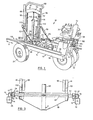
- the forklift vehicle 10 has a frame 12 formed by a pair of elongated, parallel, laterally spaced, longitudinal frame members 14, 16 and a transverse rear frame member 18 which connects the rear ends of the frame members 14, 16.
- Each frame member 14, 16 has near its front an integral, triangular, downwardly extending plate 20.
- Axles 22 of front wheels 24 are mounted on and project outwardly from the bottoms of plates 20. Since the front wheels 24 are located on the outside of the frame members 14, 16, this leaves the space between the frame members 14, 16 clear for a fork carriage 26 and fork tower 28.
- the front wheels 24 are of substantial diameter, to facilitate travel over rough terrain along a forward and rearward path of travel indicated by arrow A, which is parallel witn the frame members 14, 16.
- the rear of the vehicle 10 is supported by a pair of rear wheels 30 which are centered under the rear transverse frame member 18.
- the rear wheels 30 also serve to drive and steer the vehicle.
- the operator controls the vehicle from a seat 32 located to one side of the rear. wheels 30, and a gasoline or diesel motor 34 is located over the rear frame member 18 beside the driver's seat, where it will counterbalance the weight of the operator.
- Figs. 2 and 3 which together with Fig. 1 show the fork carriage 26 and the frame members 14, 16 in more detail.
- each frame member 14, 16 includes a box-shaped channel 36 having a U-shaped channel 38 located thereabove.
- the U-shaped channels 38 are oriented on their sides and face inwardly towards each other.
- the lower leg 40 of each U-shaped channel 38 forms an integral portion of the box-shaped channel 36, being welded to fill the gap which would otherwise be present in the box-shaped channel 38. This- avoids overlap of material and helps to lighten the forklift vehicle to reduce the load which must be transported when the forklift vehicle is being carried from one site to another.
- the upper leg 42 of the U-shaped channel 38 carries at its tip a longitudinally extending rack 44.
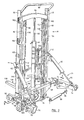
- the fork tower 28 includes (Fig. 2) a pair of vertically oriented, laterially spaced channels 46 which face inwardly towards each other and which are welded to a base 48.
- the tops of the channels 46 are connected by a U -shaped tube 50 which holds them in proper spaced relation.
- the base 48 of the fork tower 28 is pivotally and slidably mounted on a transverse tube 52, by rollers (not shown).
- Each end of the tube 52 is welded to a longl- tudinally extending hollow carriage side member 54.
- the outer side surfaces of the side members 54 carry wheels 56 which fit snugly within and roll within the U-shaped channels 38 (Fig. 3) to carry the weight of the fork carriage.
- Side thrust rollers 58 (Fig. 2) are also carried by the carriage side members 54, to act as side thrust bearings.
- the fork tower 28 can tilt in an arc extending forwardly and rearwardly.
- the forward and rearward tilting is controlled by a pair of cylinders 60.
- the butt end of each cylinder 60 is pivotally connected by a ball joint 62 to its associated upright channel 46 of the fork tower, and the rod 64 of the piston in each cylinder is pivotally connected by another ball joint 66 to its associated carriage side member 54. Extension and retraction of the piston rods 64 will tilt the tower 28 forwardly and rearwardly.
- the fork carriage 26 is propelled forwardly and rearwardly along the frame members 14, 16 as follows.
- a transverse shaft 68 (Figs. 2, 3) extends through the tube 52 and carries a drive gear 70 at each end thereof.
- the drive gears 70 (Fig. 3) engage the teeth of the rack 44 on each frame member.
- the shaft 68 Inside one of the hollow carriage side members 54, the shaft 68 carries a sprocket 72 which is connected by a drive chain 74 to a second sprocket 76.
- the sprocket 76 is mounted on the shaft of a hydraulic motor 78 secured to the carriage side member 54.
- the switch device may be returned from its "OFF” condition illustrated in Figures 6 and 7, to its normal, locked “ON” condition illustrated in Figures 4 and 5, simply by pulling the finger-hold portions 39 away from the outer wall of the collar 26. This causes the head portion 38 of the slide 30 to obstruct the spring-strip 35 again and disengage it from the button-extension 34.
- its action blocking gas admission can be overriden temporarily, e.g. for test or emergency purposes, simply by applying finger pressure to the button-extension 34 to depress the member 27 against the action of the spring-ctrip 35 and, depending upon the extent of depression, against the action of the arm 18 also. Release of such pressure restores the shut-off state appropriate to the "OFF" condition of the switch device.
- the arm 18 (and the arm 20 also) of the spring 19 is curved transversely of its width so as to increase rigidity and more precisely isolate pivotting to the shoulder 22.
- Such curvature of the arm 18, being convex in relation to the orifice 17, is also believed to have advantage in requiring less thrust for movement of the arm 18 against the force of the gas jet from the chamber 14; a flat surface exposed to the jet has also been found acceptable but a concave surface unacceptable.
- the orifice 17 may for convenience be provided by a jet-nozzle insert as illustrated, but may alternatively be simply a drilling.
- the diameter of the orifice 17 may be for example, 0.02 millimetres, and that of the aperture 15, 0.15 millimetres.
- valve there may be a simple adjustment mechanism for changing selectively the mode of operation of the valve. More particularly such mechanism may be coupled to the diaphragm 25 to impose an adjustable spring loading (inwardly, outwardly or either selectively) such that the valve operates to open in response to pressure increase or decrease on one side or other of the diaphragm.
- adjustable spring loading inwardly, outwardly or either selectively
- Such mechanism which may be adjustable to the extent necessary to shut off or open the valve completely at the wish of the user, may consist simply of a ring that carries a spring for engaging with an outward extension from the member 27 and can be screwed into or out of the collar 26 for varying the loading on the diaphragm 25 and arm 18.
- the valve of the present invention is applicable other than as a demand valve. More especially the valve may be used as a pressure-reducing valve; in the context of the construction of valve described above, stronger springing of the arm 18 or use of a spring over the top of the diaphragm 25 would normally be required to establish the reduced- pressure level. Since a reasonably constant input pressure to the valve is desirable, its application to pressure reduction would normally be as a second stage reducer.
- the lower bearing 150 has a cup 150a set in a lower recess 150b in the portion 148 and a race 150c supported on a collar 152 formed on tube 146 by machining. This arrangement supports the weight of the rear of the vehicle on the tube 146, and hence on the rear wheels 30.
- the top of the tube 146 is threaded and a ring nut 154 is mounted thereon with a collar 156 extending between ring nut 151 and race 149c.
- a hydraulic steering motor 160 is provided having a sprocket 162 connected by a chain 164 to the large sprocket 160. Operation of the hydraulic motor 160 will rotate the sprockets 162, 158 to rotate the yoke 144 through 360° in a horizontal plane, to allow steering of the vehicle in any direction.
- the drive shaft means 166 includes a lower drive shaft 168, a lower universal joint 170, an intermediate drive shaft 172 telescopically fitted into the lower universal joint 170 by splines 174, an upper universal joint 176, and an upper drive shaft 178.
- a sprocket 180 is secured to a plate 181 (Fig. 6A) at the top of the upper drive shaft 178 to receive drive from a drive chain 182 (Fig. 7).
- the upper portion of the upper drive shaft 178 is supported within the tube 146 by bearings 183 (Fig. 6A) located within the tube 146.
- the drive shaft arrangement shown allows substantial tilting of the rear wheels from side to side without affecting the stability or equilibrium of the vehicle.
- one.rear wheel may be located on a substantial bump while the other rear wheel may be locat in a dip, but if the front wheels are level, the vehicle itself will remain level.
- the large opening 184 in the yoke 144 permits the universal joint 170 to move sideways as required when the wheels tilt and when the drive shaft assumes a bent configuration, and also provides space for the differential unit 140 and to holder 141 to tilt.
- the upper universal joint 176 reduces the sideways movement of the bottom of the upper drive shaft 178 and therefore allows use of a smaller diameter yoke support tube 146.
- the motor 34 has a drive shaft 186 extending therefrom.
- a split pulley 188 has one half 190 fixedly mounted on the drive shaft 186 by splines and a conventional set screw (not shown). The other half 192 of the split pulley 188 is splined onto the shaft 186 but is free to move along the shaft in the direction of the axis of shaft 186.
- a belt 194 extends around split pulley 188 and around a larger pulley 196 which in turn is connected to a right angle gear box 198.
- a drive shaft 200 extends from the bottom of gear box 198 and carries a small sprocket 202 which is connected by the chain 182 to the sprocket 180 at the top of the upper drive shaft 178.
- Movement of the split pulley half 192 is controlled by a clutch lever 204.
- the lever 204 is pivotally mounted at 206 on the gear box 198 and carries, spaced above pivot point 206, a rod 208 which projects laterally from lever 204.
- the rod 208 is welded to a lever arm 210 which is in turn welded to a clutch rod 212 .
- the clutch rod 212 is pivotally mounted between the gear box 198 and a support strut 214.
- A-pair of fingers 216 are welded to the clutch rod 212 and extend downwardly to contact the outer face of a bushing 218 which is rotatably mounted on drive shaft 186.
- the inner end of bushing 218 contains a ball bearing race (not shown) which presses against the outer surface of the split pulley half 192.
- the clutch lever 204 is normally biased so that the clutch is disengaged. Bias is provided by a lever arm 220 having its inner end welded to clutch rod 212 and its outer end pivotally connected at 221 to a curved arm 222. The bottom of the curved arm 222 is biased downwardly by a heavy coil spring 224. The bottom of the coil spring 224 is connected to an eye bolt 226 connected to the upper transverse frame portion 148. The vertical position of eye bolt 226 is adjustable to control the tension of spring 224 and hence the clutch bias force.
- the clutch lever 204 is normally biased counter-clockwise to a disengaged position by spring 224.
- the spring 224 biases the clutch into engaged condition, thus assisting the operator in controlling the low speed creeping of the vehicle.
- the bias linkage described thus is an over-the- center linkage.
- Pulley 196a is also,a split pulley, as shown in Fig. 8A, where pulley half 196 is shown as being splined on and biased along shaft 196b by spring 196c toward pulley half 196d.
- pulley half 196 is shown as being splined on and biased along shaft 196b by spring 196c toward pulley half 196d.
- each tine 128 is hollow and has at its tip 228 a roller mount 230.
- Each roller mount 230 consists of a pair .bf triangular plates 232 spaced apart at their bottom by a shaft 233 bearing a roller 234 and held at their tops by a pin 238 pivotally connected to the sides of the tine 128.
- the rear centers of the plates 232 are connected together by a pin 238 on which one end of a rod 240 is pivotally mounted.
- the other end of rod 240 is pivotally connected at 242 to a slider 244 having a pair of rollers 246.
- the rollers 246 roll on the inside bottom spaced flanges 248 of the tine 128 and the rod 240 extends through the slot 250 between the flanges 248.
- the hoses 255 from cylinder 254 extend through the back piece 130 of the fork and then are fed with appropriate slack to the controls and pump (not shown) of the vehicle.
- the roller mount 230 is moved from the erected position shown in Figs. 9 and 11 to the retracted position shown in Fig. 10, in which the roller 234 and its mount 230 are near- l y flush with the bottom of the tine 128.
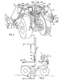
- the forklift vehicle with its fork carriage 26 moved to its rearmost position is typically moved to a side of a trailer 256 (Figs. 10, 11) containing a pallet 258 of material such as sod to be unloaded.
- the forks 118 are then raised to the desired position and the fork carriage 26 is next-moved forwardly with the vehicle stationary so that the tines 128 penetrate through the boards of the pallet 258, as, shown in Fig. 10.
- the tine rollers 234 are retracted at this time so that they will not interfere with the movement of the tines through the pallet 258.
- the cylinders 254 in the tines are activated to erect the rollers 234 so that the weight of the tips of the forks will be supported on the upper surface 260 of the trailer 256.
- the forks may be raised slightly at this time to assist in the erection of the rollers 234.
- the fork carriage 26 is then retracted rearwardly by means of the hydraulic motor 78, and as shown in Fig. 11. As indicated, t ip- ping of the forklift vehicle is prevented since the weight of the pallet 258 is partially supported by the upper surface of the trailer.
- the fork carriage 26 When the fork carriage 26 has moved rearwardly sufficiently so that the rollers 234 are clear of the trailer upper surface 260, the fork carriage 26 will have moved rearwardly sufficiently so that the load of the pallet 258 is above or slightly rearwardly of the axles 22 of the front wheels 24 of the forklift vehicle. In this position the forklift vehicle is stable and no frontwards tipping of the vehicle can occur. The forklift vehicle can then transport the load to the desired location and unload it.
- the procedure is the reverse of that described. Specifically, the forklift vehicle is driven up to the trailer with the fork carriage 26 in its rearmost position and with the forks 118 at the level desired for travel. The forks 118 are then raised to or above the desired level for loading (normally just before the trailer is reached); then the pallet rollers are erected; the load is moved slightly forwardly (by moving carriage 26 forwardly) and then lowered until the pallet rollers 234 engage the outer edge of the upper surface 260 of the trailer. The fork carriage 26 is then moved forwardly to load.the pallet 258 on the vehicle.
- shoes which spread the weight of the load on the forks over a larger area may be used.
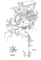
- upright ratchet bars 262 may be mounted at the fronts of the longitudinal frame members 14, 16.
- the ratchet bars 262 are removably mounted on U-shaped forwardly facing channel sections 264 secured to the front of the frame members 14, 16 and are held in position by pins 266 extending through holes (not shown) in the channel sections 264 and bars 262.
- Hairpin retainers 268 hold the pins 266 in position.
- Support sliders 270 are provided, movable vertically on the ratchet bars and having base plates 271.
- the base plates 271 contain conventional apertures to permit bars 262 to pass therethrough and retainers 273 hinged at 273a to the sliders 270.
- retainers 273 When the retainers 273 are pivotted clockwise as drawn, then internal bars 273b engage the downwardly facing teeth 274 of the ratchet bars 262 and prevent upward movement of the sliders.
- Conventional further retaining means may be provided to prevent forward or downward movement of sliders 270 on bars 262 except when desired.
- the forklift vehicle 10 is moved forwardly to the trailer 256 and the support sliders 270 are moved downwardly until they engage the upper surface of the trailer.
- the retainers 273 then engage the teeth 274 on the ratchet bars 262 to prevent the sliders from moving upwardly.
- the sliders 2 70 resting on the upper surface of the trailer 256 will prevent the forklift vehicle from tipping as pallets are loaded and unloaded with the weight of the pallets located forwardly of the front wheels 24 of the vehicle.
- F ig. 14 through 18, illustrate how the forklift vehicle may be loaded onto a trailer 256 for trahsport.
- the forklift vehicle 10 When-the forklift vehicle 10 is to be-so loaded, it is driven up to the rear of the trailer and its fork carriage 26 is moved to its most rearward position. The forks 118 are then lowered so that they almost touch the ground. The forklift vehicle is then driven forwardly so that the forks 118 move beneath the back of the trailer 256, as shown in Fig. 14, with the fork tower 28 almost touching the rear of the trailer.. The forks 118 at this time will be in their lower position, with the fork pins 134 extending through the lower holes 126 (Figs.
- Locking means shown in Figs. 15 to 17 are provided to lock the vehicle to the trailer.
- the locking means includes a pair of longitudinally extending spaced shafts 276 pivotally suspended from the cross beams 278 of the trailer by mounting plates 279.
- Each shaft 278 carries a pair of L-shaped clamps 280 welded thereto.
- the shafts 276 are rotated by lever arms 282 secured to the ends of the shaft.
- lever arms 282 are moved upwardly to press clamps 280 against the inside surfaces of upper legs 42 of the frame members 14, 16.
- the lever arms 282 are made of springy steel and have slots 283 therein, so that lever arms 282 may be forced rearwardly and then allowed to spring forwardly against the rear of the trailer so that studs 284, which are fixed to the rear of the trailer, extend through slots 283. Pins 285 are then inserted through holes in the studs 284 to lock the lever arms 282 and hence the clamps 280 in position.
- the forklift vehicle 10 may then also be chained to the rear of the trailer to prevent it from sliding rearwardly and for added security. With this arrangement, the lever arms 282 are unlikely to become unlocked, and even should this occur, the weight on the legs of the L-shaped clamps 280 is located directly below pivot shafts 276, reducing the likelihood of accidental detachment of the vehicle.
- baffles 288, 290 are welded inside the transverse frame member 18 at one side thereof to create an internal tank 292 which holds hydraulic fluid.
- the fluid may be inserted through a filler cap 294 and withdrawn through duct 296.
- Similar baffles 298, 300 are welded within the other side of the frame member 18 to create a tank 302 for fuel which may be added through filler cap 304 and withdrawn through duct 306 for use as required by the motor.
- baffles 288, 298 are welded just upwardly of the bends in the transverse frame member 18, to ensure that no leakage will occur should unusual stress cause the transverse frame member 18 to crack at its bends.
- separate tanks made for example from glass fibre material may be used, located within or supported by the frame member 18.
- wheelholders 310 may be mounted on the trailer or other vehicle which is to carry the forklift, by supports 311.
- Each wheelholder 310 is generally box-shaped, having a flattened upper plate 312 and two downwardly extending end plates 313 with outwardly flared ends 314.
- the flared ends 314 press into and deform the forklift vehicle wheels 24 (which are normally rubber tires) when the forklift vehicle is raised up against the underside of the trailer or other carrier vehicle. This assists in positioning and securing the forklift vehicle to the underside of its carrier vehicle.
- the wheelholders 310 have the configuration shown in Fig. 18, i.e. they have a downwardly and inwardly sloping inner side plate 316 and a shorter outer side plate 317.
- the plates 316 help to align the forklift vehicle in the sideways direction as it is raised on its forks toward the underside of the carrier vehicle.
- U-shaped wheelholders 318 facing rearwardly can be mounted on the carrier vehicle and a ramp 320 can be used to support the forklift vehicle so that it may be driven upwardly along the ramp until its front wheels enter wheelholders 318.
- the forks can then be used to raise the rear of the forklift vehicle so that it can be chained to its carrier vehicle.
- the wheelholders 318 can also be used without the ramps, particularly with the fork extenders next to be described, since the forklift vehicle can be raised on its forks, then the fork carriage can be operated to move the frame of the forklift vehicle forwardly until the front wheels 24 enter the wheelholders 318.
- FIGs. 20 and 21 show a fork extender 322 which may be inserted onto each fork tine 128 to extend the tines rearwardly.
- Each fork extender 322 comprises an upwardly facing elongated U-shaped channel 324 having a closed box-shaped rear portion 326. The closed rear portion 326 may simply be slid rearwardly over each tine, up to the back piece 130, with the channel 324 extending rearwardly beyond the forks. Since the forklift vehicle is typically nearly balanced above the forks when the fork carriage is in its rearmost position, the fork extenders 322 ensure that when the forks are driven below the ground, the vehicle will sit upright on its forks without tilting rearwardly.
- the feature is useful in some circumstances, for example when the vehicle is to be stored for a long period of time.
- the feature is also useful when the vehicle is mired in'mud or rough ground and cannot be driven by its wheels, in which case the vehicle can be raised above the ground by its forks, moved forwardly by operation of the fork carriage, and then set down.
- the vehicle can thus move forwardly or rearwardly in a succession of steps, by using its forks. This movement can also be accomplished without the fork extenders 322 since such self rescue operation can be carried out with the vehicle tipped rearwardly and with a small proportion of its weight on the rear wheels.
- each front leg 330 includes an upper leg portion 334 welded to its channel 36 and a jack leg 336 telescopically fitted in the upper leg portion 334 and movable upwardly and downwardly therein.
- the jack leg 336 is powered by a piston and cylinder 338 secured to the jack leg and to a fitting 339 welded to the interior of the channel 36.
- a bottom support plate 340 is pivotally secured at 342 to the bottom of the jack leg 336.
- the rear legs 332 are useful when the vehicle is being raised above the ground on its forks 168, since they limit rearward tipping of the forklift vehicle. (The rear legs 332 thus serve as an alternative to the fork extenders 322.)
- the rear legs 332 are fitted with telescopic inner extensions 342 having three positions indicated by apertures 344 in legs 342.
- a bolt (not shown) is passed through an aperture 348 in the rear leg 332 and through the appropriate aperture 344 in its inner extension 342 to secure the inner extension 342 in a desired position.
- the inner extension 342 of the rear leg includes a fixed bottom plate 350 which is aligned in a forwardly and downwardly sloping plane, rather than being horizontal. This arrangement is so that when the vehicle tilts rearwardly and the rear bottom plate 350 engages the ground, it will do so in a horizontal position.
- Figs. 22 to 26 show a modification which can be added to the forklift vehicle for power unloading of the pallet.
- one front leg 330 of the forklift is provided with a gate 352, which is simply a metal or wood plate.
- the gate 352 has a slot 354 therein and is pivotally mounted on the front leg 330 by a post 356 extending forwardly from the front leg, with an enlarged head to retain the gate on the post.
- the gate 352 is normally held in an upright position by a bolt 360 which extends through another hole in the gate 352 located above the slot 354 and then into a threaded hole 364 in the end plate of channel 36. When°the bolt 360 is removed, the gate 352 may be pivoted clockwise as drawn so that its free end rests in an upwardly facing L-shaped holder 366 secured to the front surface of the other front leg 330.
- the fork used with the gate 352 preferably has its tines and its back piece formed integrally and is indicated at 118' in Fig. 24, where primed reference numerals indicate parts corresponding to those of Fig. 2.
- the fork 118' includes a rear gate support 368 projecting above the upper surface of each tine 128' where the tine 128' meets the back piece 130'.
- the gate support 368 is of height slightly greater than the height of the upper boards 369 of a pallet 258, as shown in Figs. 25 and 26.
- each tine 128' includes a number of small serrations 370 formed on its upper surface and preferably of ramp form, having an upwardly and rearwardly sloping front surface 372 and a vertical rear surface 374.
- the operation of the pallet unloading mechanism described is as follows. Firstly, the forks are operated to move the tines 128' into and then to lift the tines against the underside of the pallet 258 to be unloaded. At this time the serrations 370 dig into the underside of the top boards 369 of the pallet.
- the fork carriage (not shown in Figs. 25 and 26) is then moved to its forwardmost position, bringing the pallet 258 ahead of the front legs 330. (The front jack legs 336 are lowered prior to moving the fork carriage forwardly.)
- the gate 352 is then unlatched and lowered across the pallet 258 so that it rests on the gate support 368 on the fork tines. The height of the forks is adjusted so that the gate 352 is approximately horizontal at this time, with the free end of the gate in holder 366. The presence of the slot 354 in the gate 352 permits some tolerance in this adjustment.
- the fork carriage 26 is then retracted rearwardly, as shown in Fig. 26.
- Rearward movement of the gate 352 is prevented by the front legs 330, and the gate 352 acts to force the contents of the pallet, here shown as rolls of sod 378, off the pallet and onto the gorund.
- the serrations or barbs-370 on the tines prevent the pallet 258 from disengaging from the fork tines at this time.
- the pallet 258 can be moved to the desired position, at which time the forks are lowered slightly, disengaging the serrations or barbs 370 from the pallet.
- the fork tines 128' can then be removed from the pallet 258.
- a hydraulic cylinder and piston and appropriate linkage may be provided to operate the gate 352 hydraulically.
- FIG. 27 and 28 An alternative gate structure for use in unloading the contents of a pallet is shown in Figs. 27 and 28, where double primed reference numerals indicate parts corresponding to those of Figs. 23 to 25.
- the forks 118" are of hollow plate construction so that the back piece 130" has a hollow interior 380.
- a pair of posts 382 extend upwardly one from each side of the top of the back piece 130".
- Each post 382 has a gear wheel 384 pivotally mounted at its top.
- a shaft 386 extends crosswise between bushings 388 located in the bottom of each post 382, just above the top of the back piece 130".
- a gear 390 is fixed to the shaft 386 and is driven by another gear 392 of a hydraulic motor 394 fixed to the fork back piece 130" and supplied with hydraulic fluid through hoses not shown. Further gears 396 are fixed to the shaft 386 adjacent to each post 382 for rotation with the shaft 386.
- Two light chains 398 are stored in the hollow interior 380, one at each side of the fork back piece 130", and extend upwardly, over the gears 396, being held there against by idler gears 400 rotatably mounted on the posts 382. The chains 398 then extend upwardly to the gears 384 at the top of the posts 382, over gears 384, and then downwardly to support a gate 352" which extends across the forks 118".
- Figs. 27 and 28 The operation of the structure shown in Figs. 27 and 28 is similar to that of the structure shown in Figs. 23 to 26.
- Normally gate 352" is held out of the way, suspended above the fork back piece 130".
- the pallet is picked up on the fork tines 128" and the fork carriage is moved to its forwardmost position, bringing the gate 352" ahead of the front legs 330A, 330B.
- the hydraulic motor 394 is then operated, unwinding the chains 398 and lowering the gate 352" so that it rests on the gate support 368".
- the forks are lowered to the desired position and the fork carriage is then retracted.
- the gate 352" is stored during non-use in a position where it does not interfere significantly with the carriage of the forklift vehicle on a trailer or other carrier vehicle and where it will interfere less with the view of the operator when he is operating the forklift vehicle.
- power operation of the gate 352" shown in Figs. 27 and 28 is simplified as compared with that of the previously described gate 352.
- the gate 342" need not be wider than a pallet if there are stop plates on the legs 330 which can be swung inwardly to add to the effective width of the gate.
- each hook 402 has a body 403 and a front barb 404 which extends upwardly from the body 403.
- the rear of the body 403 is pivoted at 405 to the tine 128 and has a band 406 of spring steel ⁇ fixed thereto and extending rearwardly therefrom.
- the band 406 passes through a slotted pin 407 extending sideways from the tine 128, and is retained by a pin 408 through pin 407.
- the rear of the band 406 can be placed either in an upper or a lower notch 409A, 409 B , in a rear holder 410 fixed to the inside surface 0 : the tine 128.
- the band 406 is in the lower notch 409B, this forces the barb 404 downwardly so that it does not project above the upper surface of its tine.
- the upwardly sloping lower surface 411 of the body 403 ensures ,'that the body 403 will be project below the lower surface of the tine 128" at this time, thus facilitating entry or retraction of the tines into or from a pallet.
- Figs. 31 to 33 illustrate two forms of a centering system for the rear driving and steering wheels 30 of the forklift vehicle.
- the forklift vehicle is both driven and steered by the rear wheels 30, and while this has substantial advantages, it can also cause certain difficulties.
- the operator may not know, even when the wheels are oriented front and aft, whether they are in a position so that the vehicle will drive forwardly or rearwardly when he engages the clutch.
- This difficulty can also be dealt with by permitting the rear driving wheels 30 to rotate only through 180°, and providing a transmission which permits forward and reverse drive to the wheels. However such a transmission would add additional weight and cost to the vehicle.
- the operator may not always know whether the wheels 30 are in fact pointed directly forwardly.
- a mechanical indicator to the steering sprocket 158.
- a gear 412 is shown connected to sprocket 158 and to a gear box 413.
- the gear box 413 is mounted on the frame portion 148 and the gears in gear box 413 are selected so that the output of the gear box, transmitted by a speedometer cable 414, is exactly matched to the turns of steering sprocket 158.
- a speedometer cable 414 is exactly matched to the turns of steering sprocket 158.
- one 360° turn of steering sprocket 158 will produce one 360° turn of cable 414.
- Cable 414 is connected to the shaft 416 of a dial indicator diagrammatically indicated at 418.
- the dial indicator (which is located beside the operator's seat 32) can be labelled "front” and "rear” to inform the operator both of the orientation of the rear wheels 30 and the direction in which they will drive.
- an automatic centering system can be provided, so that when the operator pushes a lever, the rear wheels 30 will automatically return, via the shortest distance, to a centered position in which they will drive the vehicle either forwardly or rearwardly as selected by the operator.
- a system is shown at 422 in Fig. 32, where chain dotted lines indicate hydraulic lines and solid lines indicate electrical lines.
- the centering system 422 includes an operator controlled switchbox 424 having a lever 426 spring biased to a neutral position N and which may be moved by the operator to a forward position F or a reverse position R. In its forward position F the lever 426 connects battery terminal 428 to wire 430 and ground terminal 432 to a second wire 434, while in its reverse position R the lever 426 reverses these connections. In its neutral condition N the lever opens the connections between wires 430, 435 and terminals 428, 432.
- the wires 430, 434 extend to a double-pole double- throw limit switch 436.
- the switch 436 has four contacts, namely two normally open contacts 436-1, 436-2, and two normally closed contacts 436-3, 436-4. These contacts are indicated in detached contact notation in Fig. 32, normally open contacts being indicated by an x and normally closed contacts being indicated by a dash.
- the limit switch 436 which can be a standard microswitch, has a cam follower 438 which rides on the outside surface of a semi-circular cam 440 mounted by two bolts 442 on the upper surface of the steering sprocket 158 (see also Fig. 33). When the cam follower 438 is on the cam 440, the limit switch 436 operates closing the normally open contacts 436-1, 436-2 and opening the normally closed contacts 436-3, 436-4.
- the output terminals 44, 446 of the limit switch 436 are connected to opposite ends of a solenoid four way directional valve 448 which is connected into the power steering circuit for the forklift machine.
- the power steering circuit for the forklift machine is standard, except for the directional valve 448, and includes a tank 450, and a pump 452 which supplies fluid to a coventional power steering valve 454 such as that sold under the trade mark "Orbitrol".
- the hydraulic hoses from the steering valve 454 extend in conventional manner to the hydraulic steering motor 160 and to the pump 452 and tank 450, so that the operation of the steering wheel 456 attached to the steering valve 454 will in conventional manner operate the steering motor 160 in the direction governed by the steering wheel 456.
- the four way directional valve 448 is arranged as shown so that it will override the steering valve 456 and will operate the steering motor 160 directly when valve 448 is energized. Operation is as follows.
- valve 448 Normally the four way valve 448 is spring biased to 1 '3 centre position, where it has no effect on the operation of motor 160. If now the lever 426 is moved to the forward position, this energizes the solenoid valve 448 to operate the hydraulic steering motor 160.
- the direction in which valve 448 and hence the motor 160 operates will depend on the condition of the limit switch 436.
- Hydraulic fluid then flows through hose 464, through the steering valve 454 (which is in centered position, allowing fluid to circulate freely therethrough), through hose 466, through valve spool portion 468, and through hoses 470, 472 to motor 160.
- the return path is through hoses 474, 476, valve spool system 468, and hose 478 to the tank 450.
- This drives hydraulic motor 160 and sprocket 158 clockwise to return the wheels 30 to centered and forward drive condition via the shortest route.
- cam follower 438 would have been on cam 440, reversing the polarity of the connections to valve 448.
- Hydraulic fluid would then have flowed through valve spool portion 480, reversing the flow of fluid to-hydraulic motor 160 and rotating sprocket 158 counterclockwise, again returning the wheels 30 to centered and front driving condition via the shortest path.
- cam follower 438 When the wheels 30 are rotating (for example) clockwise toward centered position as described above, cam follower 438 is off cam 440. When the wheels 30 reach and pass centered position, cam follower 438 moves onto cam 440, reversing the connections in limit switch 436 and hence reversing the condition of the valve spool of valve 448. This reverses the steering motor 160 and the wheels 30 now begin to rotate counterclockwise. The result is that the wheels 30 then oscillate back and forth slightly as the cam follower 438 comes on and off the cam 440. The oscillation tells the operator that the center position has been reached and he releases the centering lever 426 which then returns to position N, terminating operation of the steering motor 160.
- the operator desires the wheels to be centered and to drive the vehicle rearwardly, then he moves the centering lever 426 to the position R, reversing the polarity of electrical feed to the limit switch 436. This reverses the entire operation so that the wheels 30 now rotate to a position in which they will drive the vehicle rearwardly when drive is applied to the wheels 30.
- the fork carriage may be driven by means other than the rack system shown.
- it may be operated by a roller or belt drive, or by a hydraulic cylinder.
- the rack and hydraulic motor system is preferred because of its positive drive, long stroke and low weight and cost.
- the vehicle drive may be electrical rather than gasoline or diesel.
- the drive shaft means 166 (Fig. 5) may be eliminated and replaced by a hydraulic motor located in the place of the differential 140.
- ordinary automobile-type steering may be used in that event.
- the yoke 144 will still preferably be used, so that the space 184 therein will permit side to side tilting of the rear wheels.
- the forklift vehicle may be supported on the rear of a carrier vehicle (such as a trailer) simply by providing beams which can be slidably extended rearwardly from the rear of the carrier vehicle under the frame members 14, 16 after the forklift vehicle has raised sufficiently on its forks.. The forklift vehicle is then lowered onto-these beams and is tied to them by chains If desired pockets can'be provided at the rear of the carrier vehicle for the fork tines and which support the fork tines, to help position the forklift vehicle and to facilitate raising the carrier vehicle to a greater extent.
Landscapes
- Engineering & Computer Science (AREA)
- Transportation (AREA)
- Structural Engineering (AREA)
- Civil Engineering (AREA)
- Life Sciences & Earth Sciences (AREA)
- Geology (AREA)
- Mechanical Engineering (AREA)
- Chemical & Material Sciences (AREA)
- Combustion & Propulsion (AREA)
- Forklifts And Lifting Vehicles (AREA)
Abstract
Description
- This invention relates to valves, and is concerned especially, though not exclusively, with demand valves for breathing apparatus.
- The invention relates more particularly to valves of the kind in which gas flow is regulated in accordance with pressure within a control chamber, gas being supplied continuously to the control chamber and vented therefrom through a jet orifice in dependence upon deflection of a pressure-responsive member whereby the pressure within the control chamber, and accordingly flow of gas through the valve, is dependent upon such deflection. Valves of this kind (referred to hereafter as "of the kind specified") arc described in United Kingdom Patent Application No. 1569875 and United States Patent Specification No. 3467136, as used in breathing apparatus for regulating flow of gas in accordance with breathing demands. With these earlier forms of demand valve, a pressure-responsive diaphragm is located in the path of the jet of gas vented from the control chamber and responds to pressure changes caused by inhalation and exhalation of the person using the breathing apparatus to be deflected towards or away from the jet orifice according to the sense in which gas-flow through the valve is to be changed.
- Although forms of demand valve such as disclosed in the above-identified patent application and specification have been found to function satisfactorily, and (as illustrated in particular by the form described in UK Patent Application No. 15G9875) can have an especially compact and convenient construction, they do present certain practical problems. In particular the characteristics of the diaphragm and its form of mounting in the valve which are required for the diaphragm to achieve precise and consistent valve-regulation in its interaction with the jet of gas from the control chamber in some respects conflict with those which are required for the diaphragm to achieve optimum response to the pressure changes caused by inhalation and exhalation. For example, to ensure consistent interaction with the gas jet over a long service life the diaphragm is desirably of relatively hard material which will not be distorted by the gas jet itself and which has sufficiently strong restorative characteristics to retain a critical placement of the diaphragm relative to the jet after each deflection. For optimum pressure response, however, the diaphragm is desirably adapted to flex to a greater extent than is consistent with optimum jet-interaction.
- It is one of the objects of the present invention to provide a form of valve that may be used to avoid the above problems.
- According to one aspect of the present invention there is provided a valve of the kind specified wherein the pressure-responsive member is coupled to a control member which is distinct from said pressure-responsive member and which lies in the path of the jet of gas vented from the control chamber via said orifice such that deflection of the pressure-responsive member moves said control member towards or away from said orifice so as to change gas flow through the valve.
- With a valve according to the invention it is readily possible to provide the pressure-responsive member (e.g. diaphragm) in a form and with a mounting that are optimum for the achievement of the desired pressure-response characteristics. The degree of rigidity and resilience in general required for interaction with the jet of gas vented from the control chamber is no longer required of the pressure-responsive member itself, but rather can be mounted on said frame and coupled to said VErtical drive shaft means for driving said rear wheel; and steering means connected to said frame for rotating said yoke means to steer said vehicle.
- In another of its aspects, the invention provides a material handling vehicle having support and driving wheels, a first drive shaft, means connecting said first drive shaft to said wheels for driving said wheels, a motor, and clutch means coupled between said motor and said first drive shaft for enabling closely controlled slow speed creeping of said vehicle, said clutch means comprising: a second drive shaft connected to and driven by said motor, and mounted parallel to and spaced from said first drive shaft; a first split pulley mounted on said first drive shaft and a second split pulley mounted on said second drive shaft, each split pulley having a first pulley half fixed to its drive shaft and a second pulley half movable along its drive shaft; a belt extending between said pulleys; means biasing said second pulley half of said first pulley towards said first pulley half of said first pulley; means for moving said second pulley half of said second pulley along said second drive shaft to tension said belt and hence engage said clutch means when said second pulley half of said second pulley is moved towards said first pulley half of said second pulley, thus then to cause said belt to rotate to drive said wheels at a rate controlled by the speed of said motor and the spacing of said pulley halves.
- In still another aspect, the invention provides a vehicle comprising: a pair of forks facing in a predetermined direction for supporting a pallet, a frame, a fork carriage, means mounting said fork carriage on said frame for movement back and forth in said direction between an extended outer position and a retracted inner position, means mounting said forks in said fork carriage and for raising and lowering said forks, stop means mounted on said frame in a position such that when said forks are in said extended position a pallet supported thereon is located outwardly of said stop means and such that said forks may be withdrawn inwardly of said stop means, gate means, and means for supporting said gate means outwardly of said stop means and extending across said forks, so that when said gate means is located between the contents of a pallet on said forks and said stop means and then said fork carriage is withdrawn inwardly, movement of said gate inwardly will be prevented by said stop means and said gate means will act to discharge the contents of said pallet onto the ground.
- Further objects and advantages of the invention will appear from the following description, taken together with the accompanying drawings in which:
- Fig. 1 is a perspective view of a forklift vehicle according to the invention;
- Fig. 2 is a perspective view, partly exploded, showing the fork carriage, tower, mast and forks of the Fig. 1 forklift vehicle;
- Fig. 3 is a sectional view taken along lines 3-3 of Fig. 2;
- Fig. 4 is a side view showing various fork positions for the vehicle of Fig. 1;
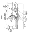
- Fig. 5 is a perspective rear view, partly exploded, of the rear frame portion, rear wheels and rear drive arrangement of the Fig. 1 vehicle;
- Fig. 6 is a partly sectional view showing the mounting of a yoke shown in Fig. 5;
- Fig. 6A is a sectional view of a metal tube shown in Fig. 6;
- Fig. 7 is a rear perspective view showing the clutch and gear box arrangement for driving the rear wheels of the forklift vehicle;
- Fig. 8 is a side view of the clutch bias linkage of Fig. 7;
- Fig. 8A is a side view of a split pulley of Fig. 7;
- Fig. 9 is a perspective bottom view of a fork of the forklift vehicle;
- Fig. 10 is a side view of the forklift vehicle of Fig. 1 showing the vehicle about to pick up a pallet of sod from a trailer;
- Fig. 11 is a view similar to that of Fig. 10 but showing the pallet of sod being retracted by the fork carriage of the forklift vehicle;
- Fig. 12 is a perspective view of the front portion of the forklift vehicle of Fig. 1, showing ratchet bars mounted therein;
- Fig. 13 is a side view of the vehicle of Fig. 1 with the bars of Fig. 12 in place and with the vehicle positioned to unload a trailer;
- Fig. 13A is a side view showing detail of the ratchet bars of Fig. 12;
- Fig. 14 is a side view of the forklift vehicle of Fig. 1, showing it raised by its forks to the underside of a trailer;
- Fig. 15 is a rear view showing clamping mechanism fitted to the underside of a trailer to secure the forklift vehicle to the trailer;
- Fig. 16 is a perspective view of a portion of the clamping mechanism of Fig. 15;
- Fig. 17 is a top view showing the clamping mechanism of Fig. 15;
- Fig. 18 is an end view, partly in seciton, showing a wheelholder for use in clamping the forklift vehicle to a carrier vehicle;
- Fig. 19 is a diagrammatic side view showing another form of wheelholder for use in securing the forklift vehicle to a carrier vehicle;
- Fig. 20 is a perspective view of a fork extender according to the invention;
- Fig. 21 is a side view showing the fork extender of Fig. 20 in position on a fork tine;
- Fig. 22 is a side view of a portion of the forklift vehicle previously shown, and showing front and rear legs thereon, and also showi-n-g an optional gate structure;
- Fig. 23 is a perspective view of the front por tion of the forklift vehicle showing the gate of Fig. 2
- Fig. 24 is a perspective view of a modified f for the forklift vehicle;
- Fig. 25 is a side view of the forklift vehicl showing a pallet on the fork and the pallet contents about to be discharged;
- Fig. 26 is a side view similar to Fig. 25 but showing the pallet contents partly discharged;
- Fig. 27 is a side view of a modified fork and gate construction according to the invention;
- Fig. 28 is a front view of the fork and gate of Fig. 27;
- Fig. 29 is a side view of a modified fork tine according to the invention;
- Fig. 30 is a top view of the fork tine of Fig. 29;
- Fig. 31 is a partly perspective view showing an indicator for showing the position of the rear wheels of the forklift vehicle;
- Fig. 32 is a plan view showing hydraulic and electric circuits for an automatic rear wheel centering mechanism according to the invention; and
- Fig. 33 is a side view showing a cam of Fig. 32.
- Reference is first made to Fig. 1, which shows a preferred form of
forklift vehicle 10 according to the invention. Theforklift vehicle 10 has aframe 12 formed by a pair of elongated, parallel, laterally spaced,longitudinal frame members rear frame member 18 which connects the rear ends of theframe members frame member plate 20.Axles 22 offront wheels 24 are mounted on and project outwardly from the bottoms ofplates 20. Since thefront wheels 24 are located on the outside of theframe members frame members fork carriage 26 andfork tower 28. Thefront wheels 24 are of substantial diameter, to facilitate travel over rough terrain along a forward and rearward path of travel indicated by arrow A, which is parallel witn theframe members - The rear of the
vehicle 10 is supported by a pair ofrear wheels 30 which are centered under the reartransverse frame member 18. Therear wheels 30 also serve to drive and steer the vehicle. The operator controls the vehicle from aseat 32 located to one side of the rear.wheels 30, and a gasoline ordiesel motor 34 is located over therear frame member 18 beside the driver's seat, where it will counterbalance the weight of the operator. - The
entire fork carriage 26 is movable front-wardly and rearwardly along theframe members fork carriage 26 and theframe members - As best shown in Fig. 3, each
frame member channel 36 having aU-shaped channel 38 located thereabove. TheU-shaped channels 38 are oriented on their sides and face inwardly towards each other. Thelower leg 40 of eachU-shaped channel 38 forms an integral portion of the box-shapedchannel 36, being welded to fill the gap which would otherwise be present in the box-shapedchannel 38. This- avoids overlap of material and helps to lighten the forklift vehicle to reduce the load which must be transported when the forklift vehicle is being carried from one site to another. Theupper leg 42 of theU-shaped channel 38 carries at its tip alongitudinally extending rack 44. - The
fork tower 28 includes (Fig. 2) a pair of vertically oriented, laterially spacedchannels 46 which face inwardly towards each other and which are welded to abase 48. The tops of thechannels 46 are connected by a U-shapedtube 50 which holds them in proper spaced relation. - The
base 48 of thefork tower 28 is pivotally and slidably mounted on atransverse tube 52, by rollers (not shown). Each end of thetube 52 is welded to a longl- tudinally extending hollowcarriage side member 54. The outer side surfaces of theside members 54 carrywheels 56 which fit snugly within and roll within the U-shaped channels 38 (Fig. 3) to carry the weight of the fork carriage. Side thrust rollers 58 (Fig. 2) are also carried by thecarriage side members 54, to act as side thrust bearings. - Since the
fork tower base 48 is pivotally mounted ontube 52, thefork tower 28 can tilt in an arc extending forwardly and rearwardly. The forward and rearward tilting is controlled by a pair ofcylinders 60. The butt end of eachcylinder 60 is pivotally connected by a ball joint 62 to its associatedupright channel 46 of the fork tower, and therod 64 of the piston in each cylinder is pivotally connected by another ball joint 66 to its associatedcarriage side member 54. Extension and retraction of thepiston rods 64 will tilt thetower 28 forwardly and rearwardly. - The
fork carriage 26 is propelled forwardly and rearwardly along theframe members tube 52 and carries adrive gear 70 at each end thereof. The drive gears 70 (Fig. 3) engage the teeth of therack 44 on each frame member. Inside one of the hollowcarriage side members 54, theshaft 68 carries asprocket 72 which is connected by adrive chain 74 to asecond sprocket 76. Thesprocket 76 is mounted on the shaft of ahydraulic motor 78 secured to thecarriage side member 54. When thehydraulic motor 78 is operated, itssprocket 76 drives thegears 70 through thechain 76 andsprockets sprockets chain 74 are located entirely within the enclosure of thecarriage side member 54, they are relatively well protected from the dirt, mud and stones which inevitably are present at construction sites. In addition, since the teeth of theracks 44 face downwardly, dirt and stones are unlikely to become wedged therein to interfere with the movement of thefork carriage 26. - To permit sideways adjustment of the
fork tower 28 allowing thestrip 35 to engage and act upon the button-extension 34 Such action upon the button-extension 34 lifts the member 27 against the bias of thearm 18 to close the valve and shut off admission of gas to the mask. Theslide 30 is retained in this position to maintain the valve closed and the admission of gas shut off, by virtue of the outward bias of the legs 37 on the walls of theslot 32. - The switch device may be returned from its "OFF" condition illustrated in Figures 6 and 7, to its normal, locked "ON" condition illustrated in Figures 4 and 5, simply by pulling the finger-hold portions 39 away from the outer wall of the
collar 26. This causes thehead portion 38 of theslide 30 to obstruct the spring-strip 35 again and disengage it from the button-extension 34. However while the switch device is in the "OFF" condition, its action blocking gas admission can be overriden temporarily, e.g. for test or emergency purposes, simply by applying finger pressure to the button-extension 34 to depress the member 27 against the action of the spring-ctrip 35 and, depending upon the extent of depression, against the action of thearm 18 also. Release of such pressure restores the shut-off state appropriate to the "OFF" condition of the switch device. - The arm 18 (and the
arm 20 also) of the spring 19 is curved transversely of its width so as to increase rigidity and more precisely isolate pivotting to theshoulder 22. Such curvature of thearm 18, being convex in relation to the orifice 17, is also believed to have advantage in requiring less thrust for movement of thearm 18 against the force of the gas jet from thechamber 14; a flat surface exposed to the jet has also been found acceptable but a concave surface unacceptable. The orifice 17 may for convenience be provided by a jet-nozzle insert as illustrated, but may alternatively be simply a drilling. - The diameter of the orifice 17 may be for example, 0.02 millimetres, and that of the aperture 15, 0.15 millimetres.
- In other embodiments of the valve there may be a simple adjustment mechanism for changing selectively the mode of operation of the valve. More particularly such mechanism may be coupled to the diaphragm 25 to impose an adjustable spring loading (inwardly, outwardly or either selectively) such that the valve operates to open in response to pressure increase or decrease on one side or other of the diaphragm. Such mechanism, which may be adjustable to the extent necessary to shut off or open the valve completely at the wish of the user, may consist simply of a ring that carries a spring for engaging with an outward extension from the member 27 and can be screwed into or out of the
collar 26 for varying the loading on the diaphragm 25 andarm 18. - The valve of the present invention is applicable other than as a demand valve. More especially the valve may be used as a pressure-reducing valve; in the context of the construction of valve described above, stronger springing of the
arm 18 or use of a spring over the top of the diaphragm 25 would normally be required to establish the reduced- pressure level. Since a reasonably constant input pressure to the valve is desirable, its application to pressure reduction would normally be as a second stage reducer. - in an upper recess 149b in the transverse
frame member portion 148 and arace 149c pressed onto thetube 146. Thelower bearing 150 has acup 150a set in alower recess 150b in theportion 148 and arace 150c supported on acollar 152 formed ontube 146 by machining. This arrangement supports the weight of the rear of the vehicle on thetube 146, and hence on therear wheels 30. The top of thetube 146 is threaded and aring nut 154 is mounted thereon with acollar 156 extending between ring nut 151 andrace 149c. Thus when the vehicle is raised, the weight of theyoke 144 and its associated mechanism will be supported from the ring nut. - Steering is achieved by a
large sprocket 158 bolted to the top of theyoke 144 beneath the transverse framemember center portion 148. Ahydraulic steering motor 160 is provided having asprocket 162 connected by achain 164 to thelarge sprocket 160. Operation of thehydraulic motor 160 will rotate thesprockets yoke 144 through 360° in a horizontal plane, to allow steering of the vehicle in any direction. - Drive to the
rear wheels 30 is provided via drive shaft means generally indicated at 166 (Fig. 5). The drive shaft means 166 includes a lower drive shaft 168, a loweruniversal joint 170, anintermediate drive shaft 172 telescopically fitted into the loweruniversal joint 170 bysplines 174, an upperuniversal joint 176, and anupper drive shaft 178. Asprocket 180 is secured to a plate 181 (Fig. 6A) at the top of theupper drive shaft 178 to receive drive from a drive chain 182 (Fig. 7). The upper portion of theupper drive shaft 178 is supported within thetube 146 by bearings 183 (Fig. 6A) located within thetube 146. - The drive shaft arrangement shown, with the universal joints 170,176 and telescopic center portion, allows substantial tilting of the rear wheels from side to side without affecting the stability or equilibrium of the vehicle. For example, one.rear wheel may be located on a substantial bump while the other rear wheel may be locat in a dip, but if the front wheels are level, the vehicle itself will remain level. The
large opening 184 in theyoke 144 permits theuniversal joint 170 to move sideways as required when the wheels tilt and when the drive shaft assumes a bent configuration, and also provides space for the differential unit 140 and toholder 141 to tilt. The upperuniversal joint 176 reduces the sideways movement of the bottom of theupper drive shaft 178 and therefore allows use of a smaller diameteryoke support tube 146. - The manner in which the speed of the vehicle is controlled will next be described. As shown in Fig. 7, the
motor 34 has adrive shaft 186 extending therefrom. - A
split pulley 188 has onehalf 190 fixedly mounted on thedrive shaft 186 by splines and a conventional set screw (not shown). Theother half 192 of the splitpulley 188 is splined onto theshaft 186 but is free to move along the shaft in the direction of the axis ofshaft 186. Abelt 194 extends around splitpulley 188 and around alarger pulley 196 which in turn is connected to a rightangle gear box 198. Adrive shaft 200 extends from the bottom ofgear box 198 and carries asmall sprocket 202 which is connected by thechain 182 to thesprocket 180 at the top of theupper drive shaft 178. Thus, when themovable half 192 of splitpulley 188 is pushed inwardly towards thefixed half 190 to raise thebelt 194 on the pulley sufficiently to tension the belt, power is transmitted from the motor to therear wheels 30. - Movement of the split
pulley half 192 is controlled by aclutch lever 204. Thelever 204 is pivotally mounted at 206 on thegear box 198 and carries, spaced abovepivot point 206, arod 208 which projects laterally fromlever 204. Therod 208 is welded to alever arm 210 which is in turn welded to aclutch rod 212 . Theclutch rod 212 is pivotally mounted between thegear box 198 and asupport strut 214. A-pair offingers 216 are welded to theclutch rod 212 and extend downwardly to contact the outer face of abushing 218 which is rotatably mounted ondrive shaft 186. The inner end ofbushing 218 contains a ball bearing race (not shown) which presses against the outer surface of the splitpulley half 192. - The
clutch lever 204 is normally biased so that the clutch is disengaged. Bias is provided by alever arm 220 having its inner end welded toclutch rod 212 and its outer end pivotally connected at 221 to acurved arm 222. The bottom of thecurved arm 222 is biased downwardly by aheavy coil spring 224. The bottom of thecoil spring 224 is connected to aneye bolt 226 connected to the uppertransverse frame portion 148. The vertical position ofeye bolt 226 is adjustable to control the tension ofspring 224 and hence the clutch bias force. - In operation of the clutch mechanism, when the clutch lever"204 is moved clockwise as drawn in Fig. 7, the
fingers 216 are also rotated clockwise to push thebushing 218 inwardly on theshaft 186. This tensions thebelt 194 and produces drive to therear wheels 30. The speed of the motor can be left constant at this time, and a very low speed creeping drive can be achieved, the rate of which is closely controllable by movement of theclutch lever 204. Such very low speed closely controllable creeping drive is extremely advantageous when loading and unloading on rough terrain when very small movements are required to adjust the position of the forklift vehicle. - As described and as will be apparent from Fig. 8, the
clutch lever 204 is normally biased counter-clockwise to a disengaged position byspring 224. However, when theclutch lever 204 is rotated clockwise sufficiently to carry thepivotal connection 221 ofarms clutch rod 212, then thespring 224 biases the clutch into engaged condition, thus assisting the operator in controlling the low speed creeping of the vehicle. The bias linkage described thus is an over-the- center linkage. -
Pulley 196a is also,a split pulley, as shown in Fig. 8A, wherepulley half 196 is shown as being splined on and biased alongshaft 196b byspring 196c towardpulley half 196d. Thus, as the effective diameter ofpulley 188 increases, that ofpulley 196 decreases (since the pressure of the beltforces pulley halves - Reference is next made to Fig. 9, which shows in more detail the construction of a
fork tine 128. As shown, eachtine 128 is hollow and has at its tip 228 aroller mount 230. Eachroller mount 230 consists of a pair .bftriangular plates 232 spaced apart at their bottom by ashaft 233 bearing aroller 234 and held at their tops by apin 238 pivotally connected to the sides of thetine 128. The rear centers of theplates 232 are connected together by apin 238 on which one end of arod 240 is pivotally mounted. The other end ofrod 240 is pivotally connected at 242 to aslider 244 having a pair ofrollers 246. Therollers 246 roll on the inside bottom spacedflanges 248 of thetine 128 and therod 240 extends through theslot 250 between theflanges 248. Connected to theslider 244 is apiston rod 252 of ahydraulic cylinder 254. Thehoses 255 fromcylinder 254 extend through theback piece 130 of the fork and then are fed with appropriate slack to the controls and pump (not shown) of the vehicle. - As the
tine piston rod 252 is extended and retracted, theroller mount 230 is moved from the erected position shown in Figs. 9 and 11 to the retracted position shown in Fig. 10, in which theroller 234 and itsmount 230 are near- ly flush with the bottom of thetine 128. - In operation, the forklift vehicle with its
fork carriage 26 moved to its rearmost position is typically moved to a side of a trailer 256 (Figs. 10, 11) containing apallet 258 of material such as sod to be unloaded. Theforks 118 are then raised to the desired position and thefork carriage 26 is next-moved forwardly with the vehicle stationary so that thetines 128 penetrate through the boards of thepallet 258, as, shown in Fig. 10. Thetine rollers 234 are retracted at this time so that they will not interfere with the movement of the tines through thepallet 258. - When the
tines 128 have penetrated through the pallet, thecylinders 254 in the tines are activated to erect therollers 234 so that the weight of the tips of the forks will be supported on theupper surface 260 of thetrailer 256. The forks may be raised slightly at this time to assist in the erection of therollers 234. While theforklift vehicle 10 remains stationary, thefork carriage 26 is then retracted rearwardly by means of thehydraulic motor 78, and as shown in Fig. 11. As indicated, tip- ping of the forklift vehicle is prevented since the weight of thepallet 258 is partially supported by the upper surface of the trailer. - When the
fork carriage 26 has moved rearwardly sufficiently so that therollers 234 are clear of the trailerupper surface 260, thefork carriage 26 will have moved rearwardly sufficiently so that the load of thepallet 258 is above or slightly rearwardly of theaxles 22 of thefront wheels 24 of the forklift vehicle. In this position the forklift vehicle is stable and no frontwards tipping of the vehicle can occur. The forklift vehicle can then transport the load to the desired location and unload it. - To load a
pallet 258 on atrailer 256, the procedure is the reverse of that described. Specifically, the forklift vehicle is driven up to the trailer with thefork carriage 26 in its rearmost position and with theforks 118 at the level desired for travel. Theforks 118 are then raised to or above the desired level for loading (normally just before the trailer is reached); then the pallet rollers are erected; the load is moved slightly forwardly (by movingcarriage 26 forwardly) and then lowered until thepallet rollers 234 engage the outer edge of theupper surface 260 of the trailer. Thefork carriage 26 is then moved forwardly to load.thepallet 258 on the vehicle. - Instead of
rollers 234, shoes which spread the weight of the load on the forks over a larger area may be used. - In some cases it may be desired to load or st. pat-lets 258 one above the other, and if the upper surfa. of the material on the pallet is uneven, or unable to bear a concentrated load, then the
tine rollers 234 of Fig. 9 cannot be used. In that case, and as shown in Figs. 12, 13 and 13A, upright ratchet bars 262 may be mounted at the fronts of thelongitudinal frame members channel sections 264 secured to the front of theframe members pins 266 extending through holes (not shown) in thechannel sections 264 and bars 262.Hairpin retainers 268 hold thepins 266 in position.Support sliders 270 are provided, movable vertically on the ratchet bars and havingbase plates 271. Thebase plates 271 contain conventional apertures to permitbars 262 to pass therethrough andretainers 273 hinged at 273a to thesliders 270. When theretainers 273 are pivotted clockwise as drawn, theninternal bars 273b engage the downwardly facingteeth 274 of the ratchet bars 262 and prevent upward movement of the sliders. Conventional further retaining means, not shown, may be provided to prevent forward or downward movement ofsliders 270 onbars 262 except when desired. - In operation, and as shown in Fig. 13, the
forklift vehicle 10 is moved forwardly to thetrailer 256 and thesupport sliders 270 are moved downwardly until they engage the upper surface of the trailer. Theretainers 273 then engage theteeth 274 on the ratchet bars 262 to prevent the sliders from moving upwardly. The sliders 270 resting on the upper surface of thetrailer 256 will prevent the forklift vehicle from tipping as pallets are loaded and unloaded with the weight of the pallets located forwardly of thefront wheels 24 of the vehicle. - Reference is next made to Fig. 14 through 18, which illustrate how the forklift vehicle may be loaded onto a
trailer 256 for trahsport. When-theforklift vehicle 10 is to be-so loaded, it is driven up to the rear of the trailer and itsfork carriage 26 is moved to its most rearward position. Theforks 118 are then lowered so that they almost touch the ground. The forklift vehicle is then driven forwardly so that theforks 118 move beneath the back of thetrailer 256, as shown in Fig. 14, with thefork tower 28 almost touching the rear of the trailer.. Theforks 118 at this time will be in their lower position, with the fork pins 134 extending through the lower holes 126 (Figs. 2, 4) in thefork holder extensions 122. Themast piston rod 100 is then retracted, forcing theforks 118 downwardly and raising the forklift vehicle off the ground. The rear of the forklift vehicle may tend to tilt rearwardly at this time, but as soon as the forward ends of theframe members frame members beams 276 mounted on the underside of thetrailer 256. - Locking means shown in Figs. 15 to 17 are provided to lock the vehicle to the trailer. The locking means includes a pair of longitudinally extending spaced
shafts 276 pivotally suspended from the cross beams 278 of the trailer by mountingplates 279. Eachshaft 278 carries a pair of L-shapedclamps 280 welded thereto. Theshafts 276 are rotated bylever arms 282 secured to the ends of the shaft. As shown in Figs. 15 and 16, when the forkliftvehicle frame members arms 282 are moved upwardly to pressclamps 280 against the inside surfaces ofupper legs 42 of theframe members lever arms 282 are made of springy steel and haveslots 283 therein, so thatlever arms 282 may be forced rearwardly and then allowed to spring forwardly against the rear of the trailer so thatstuds 284, which are fixed to the rear of the trailer, extend throughslots 283.Pins 285 are then inserted through holes in thestuds 284 to lock thelever arms 282 and hence theclamps 280 in position. Theforklift vehicle 10 may then also be chained to the rear of the trailer to prevent it from sliding rearwardly and for added security. With this arrangement, thelever arms 282 are unlikely to become unlocked, and even should this occur, the weight on the legs of the L-shapedclamps 280 is located directly belowpivot shafts 276, reducing the likelihood of accidental detachment of the vehicle. - The weight of the forklift vehicle may be kept to a minimum by using the rear
transverse frame member 18 to hold fuel and hydraulic fluid. As shown in Fig. 5, baffles 288, 290 are welded inside thetransverse frame member 18 at one side thereof to create aninternal tank 292 which holds hydraulic fluid. The fluid may be inserted through afiller cap 294 and withdrawn throughduct 296.Similar baffles frame member 18 to create atank 302 for fuel which may be added throughfiller cap 304 and withdrawn throughduct 306 for use as required by the motor. It will be seen that thebaffles 288, 298 are welded just upwardly of the bends in thetransverse frame member 18, to ensure that no leakage will occur should unusual stress cause thetransverse frame member 18 to crack at its bends. Of course separate tanks made for example from glass fibre material may be used, located within or supported by theframe member 18. - If desired, and as shown in Figs. 14 and 18,
wheelholders 310 may be mounted on the trailer or other vehicle which is to carry the forklift, by supports 311. Eachwheelholder 310 is generally box-shaped, having a flattenedupper plate 312 and two downwardly extendingend plates 313 with outwardly flared ends 314. The flared ends 314 press into and deform the forklift vehicle wheels 24 (which are normally rubber tires) when the forklift vehicle is raised up against the underside of the trailer or other carrier vehicle. This assists in positioning and securing the forklift vehicle to the underside of its carrier vehicle. - From the end, the
wheelholders 310 have the configuration shown in Fig. 18, i.e. they have a downwardly and inwardly slopinginner side plate 316 and a shorterouter side plate 317. Theplates 316 help to align the forklift vehicle in the sideways direction as it is raised on its forks toward the underside of the carrier vehicle. - If desired, and as shown diagrammatically in Fig. 19,
U-shaped wheelholders 318 facing rearwardly can be mounted on the carrier vehicle and aramp 320 can be used to support the forklift vehicle so that it may be driven upwardly along the ramp until its front wheels enterwheelholders 318. The forks can then be used to raise the rear of the forklift vehicle so that it can be chained to its carrier vehicle. Thewheelholders 318 can also be used without the ramps, particularly with the fork extenders next to be described, since the forklift vehicle can be raised on its forks, then the fork carriage can be operated to move the frame of the forklift vehicle forwardly until thefront wheels 24 enter thewheelholders 318. - Reference is next made to Figs. 20 and 21, which show a
fork extender 322 which may be inserted onto eachfork tine 128 to extend the tines rearwardly. Eachfork extender 322 comprises an upwardly facing elongatedU-shaped channel 324 having a closed box-shapedrear portion 326. The closedrear portion 326 may simply be slid rearwardly over each tine, up to theback piece 130, with thechannel 324 extending rearwardly beyond the forks. Since the forklift vehicle is typically nearly balanced above the forks when the fork carriage is in its rearmost position, thefork extenders 322 ensure that when the forks are driven below the ground, the vehicle will sit upright on its forks without tilting rearwardly. This is useful in some circumstances, for example when the vehicle is to be stored for a long period of time. The feature is also useful when the vehicle is mired in'mud or rough ground and cannot be driven by its wheels, in which case the vehicle can be raised above the ground by its forks, moved forwardly by operation of the fork carriage, and then set down. The vehicle can thus move forwardly or rearwardly in a succession of steps, by using its forks. This movement can also be accomplished without thefork extenders 322 since such self rescue operation can be carried out with the vehicle tipped rearwardly and with a small proportion of its weight on the rear wheels. - In some operating conditions, it may be advantageous to fit the
forklift vehicle 10 with front andrear legs front legs 330, one extending downwardly from the front of eachframe member front leg 330 includes anupper leg portion 334 welded to itschannel 36 and ajack leg 336 telescopically fitted in theupper leg portion 334 and movable upwardly and downwardly therein. Thejack leg 336 is powered by a piston andcylinder 338 secured to the jack leg and to a fitting 339 welded to the interior of thechannel 36. Abottom support plate 340 is pivotally secured at 342 to the bottom of thejack leg 336. - In a machine having the proportions shown in the drawings, and weighing about 2,300 pounds, it has been found that with the
front legs 330 extended downwardly to support the front of the vehicle, and with thefork carriage 26 at its forward most position, a load of at least 4,500 pounds can be placed on the forks without tipping the machine forwardly. Since this exceeds most loads which the forklift will usually be required to handle, the forklift vehicle in use can be moved forwardly to the side of a trailer or other vehicle to be unloaded; thefront jack legs 336 can be lowered to support the weight of the front of the forklift vehicle, and thefork carriage 26 can then be moved forwardly to engage and lift a load on the vehicle without fear of the forklift vehicle tipping. When thefront legs 330 are used,'the roller support system for the fork tines shown in Fig. 9, and the support posts 262 shown in Fig. 12, can be eliminated. - The
rear legs 332 are useful when the vehicle is being raised above the ground on its forks 168, since they limit rearward tipping of the forklift vehicle. (Therear legs 332 thus serve as an alternative to thefork extenders 322.) Therear legs 332 are fitted with telescopicinner extensions 342 having three positions indicated byapertures 344 inlegs 342. A bolt (not shown) is passed through anaperture 348 in therear leg 332 and through theappropriate aperture 344 in itsinner extension 342 to secure theinner extension 342 in a desired position. It will be noted that theinner extension 342 of the rear leg includes a fixedbottom plate 350 which is aligned in a forwardly and downwardly sloping plane, rather than being horizontal. This arrangement is so that when the vehicle tilts rearwardly and therear bottom plate 350 engages the ground, it will do so in a horizontal position. - In some applications of the forklift vehicle, it will be desired to unload onto the ground the contents of the pallet carried by the vehicle. For example, when the vehicle is carrying pallets of sod to be laid on the ground, it may be desirable to unload all of the sod from a pallet, so that the pallet can then be removed without waiting for the pallet to be manually unloaded. Reference is therefore made to Figs. 22 to 26, which show a modification which can be added to the forklift vehicle for power unloading of the pallet.
- As best shown in Fig. 23, one
front leg 330 of the forklift is provided with agate 352, which is simply a metal or wood plate. Thegate 352 has aslot 354 therein and is pivotally mounted on thefront leg 330 by apost 356 extending forwardly from the front leg, with an enlarged head to retain the gate on the post. Thegate 352 is normally held in an upright position by abolt 360 which extends through another hole in thegate 352 located above theslot 354 and then into a threadedhole 364 in the end plate ofchannel 36. When°thebolt 360 is removed, thegate 352 may be pivoted clockwise as drawn so that its free end rests in an upwardly facing L-shapedholder 366 secured to the front surface of the otherfront leg 330. - The fork used with the
gate 352 preferably has its tines and its back piece formed integrally and is indicated at 118' in Fig. 24, where primed reference numerals indicate parts corresponding to those of Fig. 2. The fork 118' includes arear gate support 368 projecting above the upper surface of each tine 128' where the tine 128' meets the back piece 130'. Thegate support 368 is of height slightly greater than the height of theupper boards 369 of apallet 258, as shown in Figs. 25 and 26. In addition each tine 128' includes a number ofsmall serrations 370 formed on its upper surface and preferably of ramp form, having an upwardly and rearwardly slopingfront surface 372 and a verticalrear surface 374. - The operation of the pallet unloading mechanism described is as follows. Firstly, the forks are operated to move the tines 128' into and then to lift the tines against the underside of the
pallet 258 to be unloaded. At this time theserrations 370 dig into the underside of thetop boards 369 of the pallet. The fork carriage (not shown in Figs. 25 and 26) is then moved to its forwardmost position, bringing thepallet 258 ahead of thefront legs 330. (Thefront jack legs 336 are lowered prior to moving the fork carriage forwardly.) Thegate 352 is then unlatched and lowered across thepallet 258 so that it rests on thegate support 368 on the fork tines. The height of the forks is adjusted so that thegate 352 is approximately horizontal at this time, with the free end of the gate inholder 366. The presence of theslot 354 in thegate 352 permits some tolerance in this adjustment. - The
fork carriage 26 is then retracted rearwardly, as shown in Fig. 26. Rearward movement of thegate 352 is prevented by thefront legs 330, and thegate 352 acts to force the contents of the pallet, here shown as rolls ofsod 378, off the pallet and onto the gorund. The serrations or barbs-370 on the tines prevent thepallet 258 from disengaging from the fork tines at this time. - After the contents of the pallet have been discharged, the
pallet 258 can be moved to the desired position, at which time the forks are lowered slightly, disengaging the serrations orbarbs 370 from the pallet. The fork tines 128' can then be removed from thepallet 258. - If desired, a hydraulic cylinder and piston and appropriate linkage may be provided to operate the
gate 352 hydraulically. - An alternative gate structure for use in unloading the contents of a pallet is shown in Figs. 27 and 28, where double primed reference numerals indicate parts corresponding to those of Figs. 23 to 25. In the Figs. 27 and 28 embodiment, the
forks 118" are of hollow plate construction so that theback piece 130" has ahollow interior 380. A pair ofposts 382 extend upwardly one from each side of the top of theback piece 130". Eachpost 382 has agear wheel 384 pivotally mounted at its top. Ashaft 386 extends crosswise betweenbushings 388 located in the bottom of eachpost 382, just above the top of theback piece 130". A gear 390 is fixed to theshaft 386 and is driven by anothergear 392 of ahydraulic motor 394 fixed to the fork backpiece 130" and supplied with hydraulic fluid through hoses not shown. Further gears 396 are fixed to theshaft 386 adjacent to eachpost 382 for rotation with theshaft 386. Twolight chains 398 are stored in thehollow interior 380, one at each side of the fork backpiece 130", and extend upwardly, over thegears 396, being held there against byidler gears 400 rotatably mounted on theposts 382. Thechains 398 then extend upwardly to thegears 384 at the top of theposts 382, overgears 384, and then downwardly to support agate 352" which extends across theforks 118". - The operation of the structure shown in Figs. 27 and 28 is similar to that of the structure shown in Figs. 23 to 26. Normally
gate 352" is held out of the way, suspended above the fork backpiece 130". When the contents of apallet 258 are to be unloaded, the pallet is picked up on thefork tines 128" and the fork carriage is moved to its forwardmost position, bringing thegate 352" ahead of the front legs 330A, 330B. Thehydraulic motor 394 is then operated, unwinding thechains 398 and lowering thegate 352" so that it rests on thegate support 368". The forks are lowered to the desired position and the fork carriage is then retracted. Rearward movement of thegate 352" is blocked by the front legs 330A, 330B, and as retraction of the fork carriage continues, the contents of the pallet are ejected from the pallet. Sufficient slack chain should be unwound from thechains 398 stored in the fork backpiece 130" so that thegate 352" can move forwardly relative to the rearward movement of theforks 118" at this time. After the ejection process has been completed, thehydraulic motor 394 is operated to rewind thechains 392 and lift thegate 352 upwardly out of the way of a loaded pallet. Thechains 398 simply coil in theinterior space 380 of the fork backpiece 130" at this time. The arrangement shown in Figs. 27 and 28 has the advantage that thegate 352" is stored during non-use in a position where it does not interfere significantly with the carriage of the forklift vehicle on a trailer or other carrier vehicle and where it will interfere less with the view of the operator when he is operating the forklift vehicle. In addition, power operation of thegate 352" shown in Figs. 27 and 28 is simplified as compared with that of the previously describedgate 352. Thegate 342" need not be wider than a pallet if there are stop plates on thelegs 330 which can be swung inwardly to add to the effective width of the gate. - Instead of
serrations 370 being provided on thefork tines 128", the fork tines may instead each be provided with ahook 402, as shown in Figs. 29 and 30. As there shown, eachhook 402 has abody 403 and afront barb 404 which extends upwardly from thebody 403. The rear of thebody 403 is pivoted at 405 to thetine 128 and has aband 406 of spring steel·fixed thereto and extending rearwardly therefrom. Theband 406 passes through a slottedpin 407 extending sideways from thetine 128, and is retained by apin 408 throughpin 407. The rear of theband 406 can be placed either in an upper or a lower notch 409A, 409B, in arear holder 410 fixed to the inside surface 0: thetine 128. When theband 406 is located in the upper notch 409A, this forces thebarb 404 upwardly so that it projects for example about 3/4 of an inch above the top surface of its tine. When theband 406 is in the lower notch 409B, this forces thebarb 404 downwardly so that it does not project above the upper surface of its tine. The upwardly slopinglower surface 411 of thebody 403 ensures ,'that thebody 403 will be project below the lower surface of thetine 128" at this time, thus facilitating entry or retraction of the tines into or from a pallet. - Reference is next made to Figs. 31 to 33, which illustrate two forms of a centering system for the rear driving and
steering wheels 30 of the forklift vehicle. As previously described, the forklift vehicle is both driven and steered by therear wheels 30, and while this has substantial advantages, it can also cause certain difficulties. Firstly, the operator may not know, even when the wheels are oriented front and aft, whether they are in a position so that the vehicle will drive forwardly or rearwardly when he engages the clutch. This difficulty can also be dealt with by permitting therear driving wheels 30 to rotate only through 180°, and providing a transmission which permits forward and reverse drive to the wheels. However such a transmission would add additional weight and cost to the vehicle. Secondly, the operator may not always know whether thewheels 30 are in fact pointed directly forwardly. - Both of the above difficulties can be dealt with by connecting a mechanical indicator to the
steering sprocket 158. Such an arrangement is shown in Fig. 31, where agear 412 is shown connected tosprocket 158 and to a gear box 413. The gear box 413 is mounted on theframe portion 148 and the gears in gear box 413 are selected so that the output of the gear box, transmitted by aspeedometer cable 414, is exactly matched to the turns ofsteering sprocket 158. In other words, one 360° turn ofsteering sprocket 158 will produce one 360° turn ofcable 414.Cable 414 is connected to theshaft 416 of a dial indicator diagrammatically indicated at 418. Since one turn of needle 420 corresponds exactly to one turn ofsteering sprocket 158, the dial indicator (which is located beside the operator's seat 32) can be labelled "front" and "rear" to inform the operator both of the orientation of therear wheels 30 and the direction in which they will drive. - Alternatively, an automatic centering system can be provided, so that when the operator pushes a lever, the
rear wheels 30 will automatically return, via the shortest distance, to a centered position in which they will drive the vehicle either forwardly or rearwardly as selected by the operator. Such a system is shown at 422 in Fig. 32, where chain dotted lines indicate hydraulic lines and solid lines indicate electrical lines. - The centering
system 422 includes an operator controlledswitchbox 424 having alever 426 spring biased to a neutral position N and which may be moved by the operator to a forward position F or a reverse position R. In its forward position F thelever 426 connectsbattery terminal 428 towire 430 andground terminal 432 to asecond wire 434, while in its reverse position R thelever 426 reverses these connections. In its neutral condition N the lever opens the connections betweenwires 430, 435 andterminals - The
wires throw limit switch 436. Theswitch 436 has four contacts, namely two normally open contacts 436-1, 436-2, and two normally closed contacts 436-3, 436-4. These contacts are indicated in detached contact notation in Fig. 32, normally open contacts being indicated by an x and normally closed contacts being indicated by a dash. - The
limit switch 436, which can be a standard microswitch, has acam follower 438 which rides on the outside surface of asemi-circular cam 440 mounted by twobolts 442 on the upper surface of the steering sprocket 158 (see also Fig. 33). When thecam follower 438 is on thecam 440, thelimit switch 436 operates closing the normally open contacts 436-1, 436-2 and opening the normally closed contacts 436-3, 436-4. - The
output terminals 44, 446 of thelimit switch 436 are connected to opposite ends of a solenoid four waydirectional valve 448 which is connected into the power steering circuit for the forklift machine. - The power steering circuit for the forklift machine is standard, except for the
directional valve 448, and includes atank 450, and apump 452 which supplies fluid to a coventional power steering valve 454 such as that sold under the trade mark "Orbitrol". The hydraulic hoses from the steering valve 454 extend in conventional manner to thehydraulic steering motor 160 and to thepump 452 andtank 450, so that the operation of thesteering wheel 456 attached to the steering valve 454 will in conventional manner operate thesteering motor 160 in the direction governed by thesteering wheel 456. - The four way
directional valve 448 is arranged as shown so that it will override thesteering valve 456 and will operate thesteering motor 160 directly whenvalve 448 is energized. Operation is as follows. - Normally the four
way valve 448 is spring biased to 1'3 centre position, where it has no effect on the operation ofmotor 160. If now thelever 426 is moved to the forward position, this energizes thesolenoid valve 448 to operate thehydraulic steering motor 160. The direction in whichvalve 448 and hence themotor 160 operates will depend on the condition of thelimit switch 436. - Assume that in the position drawn in Fig. 32, the
wheels 30 will drive the vehicle forwardly, and assume further that the fronts ofwheels 30 have then been shifted 90° counter- clockwise from the position drawn, so thatcam follower 438 is off thecam 440. Then, withlever 426 in position F, battery is connected fromterminal 428 throughwire 430, through contact 436-2, and through terminal 446 to terminal 460 of solenoid valve 448'. Ground is similarly connected toterminal 462 ofvalve 448. This shifts the valve spool to the right as drawn. Hydraulic fluid then flows throughhose 464, through the steering valve 454 (which is in centered position, allowing fluid to circulate freely therethrough), throughhose 466, throughvalve spool portion 468, and throughhoses motor 160. The return path is throughhoses 474, 476,valve spool system 468, andhose 478 to thetank 450. This driveshydraulic motor 160 andsprocket 158 clockwise to return thewheels 30 to centered and forward drive condition via the shortest route. Had the fronts ofwheels 30 been shifted to the right, i.e. clockwise, from the position drawn, thencam follower 438 would have been oncam 440, reversing the polarity of the connections tovalve 448. Hydraulic fluid would then have flowed throughvalve spool portion 480, reversing the flow of fluid to-hydraulic motor 160 androtating sprocket 158 counterclockwise, again returning thewheels 30 to centered and front driving condition via the shortest path. - When the
wheels 30 are rotating (for example) clockwise toward centered position as described above,cam follower 438 is offcam 440. When thewheels 30 reach and pass centered position,cam follower 438 moves ontocam 440, reversing the connections inlimit switch 436 and hence reversing the condition of the valve spool ofvalve 448. This reverses thesteering motor 160 and thewheels 30 now begin to rotate counterclockwise. The result is that thewheels 30 then oscillate back and forth slightly as thecam follower 438 comes on and off thecam 440. The oscillation tells the operator that the center position has been reached and he releases the centeringlever 426 which then returns to position N, terminating operation of thesteering motor 160. - If the operator desires the wheels to be centered and to drive the vehicle rearwardly, then he moves the centering
lever 426 to the position R, reversing the polarity of electrical feed to thelimit switch 436. This reverses the entire operation so that thewheels 30 now rotate to a position in which they will drive the vehicle rearwardly when drive is applied to thewheels 30. - When the centering
lever 426 is returned to neutral position, the four waydirectional valve 448 returns under spring bias to its center position as drawn, blocking fluid flow throughhoses - It will be seen that whatever the position of the
wheels 30, they will always turn 180° or less to the position selected by the operator, and will never be required to turn more than 180° to the selected position. - Although two rear driving and steering wheels have been shown, it will be appreciated that only one wheel may be used if desired, substantially preferably centered under the rear frame member.
- It will be appreciated that various features of the invention, for example the clutch mechanism for permitting low speed creeping, may be used in material handling vehicles other than forklift vehicles.
- It will also.be appreciated that the fork carriage may be driven by means other than the rack system shown. For example it may be operated by a roller or belt drive, or by a hydraulic cylinder. However, the rack and hydraulic motor system is preferred because of its positive drive, long stroke and low weight and cost.
- If desired, the vehicle drive may be electrical rather than gasoline or diesel. In addition, the drive shaft means 166 (Fig. 5) may be eliminated and replaced by a hydraulic motor located in the place of the differential 140. In addition, ordinary automobile-type steering may be used in that event. However the
yoke 144 will still preferably be used, so that thespace 184 therein will permit side to side tilting of the rear wheels. - If desired, the forklift vehicle may be supported on the rear of a carrier vehicle (such as a trailer) simply by providing beams which can be slidably extended rearwardly from the rear of the carrier vehicle under the
frame members
Claims (14)
Applications Claiming Priority (2)
| Application Number | Priority Date | Filing Date | Title |
|---|---|---|---|
| CA330,327A CA1113891A (en) | 1979-06-21 | 1979-06-21 | Forklift vehicle |
| CA330327 | 1979-06-21 |
Related Child Applications (2)
| Application Number | Title | Priority Date | Filing Date |
|---|---|---|---|
| EP83200739A Division-Into EP0120149A1 (en) | 1979-06-21 | 1980-06-20 | Forklift vehicle |
| EP83200739A Division EP0120149A1 (en) | 1979-06-21 | 1980-06-20 | Forklift vehicle |
Publications (2)
| Publication Number | Publication Date |
|---|---|
| EP0021805A1 true EP0021805A1 (en) | 1981-01-07 |
| EP0021805B1 EP0021805B1 (en) | 1985-12-11 |
Family
ID=4114520
Family Applications (2)
| Application Number | Title | Priority Date | Filing Date |
|---|---|---|---|
| EP80302085A Expired EP0021805B1 (en) | 1979-06-21 | 1980-06-20 | Forklift vehicle |
| EP83200739A Withdrawn EP0120149A1 (en) | 1979-06-21 | 1980-06-20 | Forklift vehicle |
Family Applications After (1)
| Application Number | Title | Priority Date | Filing Date |
|---|---|---|---|
| EP83200739A Withdrawn EP0120149A1 (en) | 1979-06-21 | 1980-06-20 | Forklift vehicle |
Country Status (6)
| Country | Link |
|---|---|
| US (2) | US4365921A (en) |
| EP (2) | EP0021805B1 (en) |
| JP (1) | JPS5643197A (en) |
| AU (1) | AU533657B2 (en) |
| CA (1) | CA1113891A (en) |
| DE (1) | DE3071284D1 (en) |
Cited By (7)
| Publication number | Priority date | Publication date | Assignee | Title |
|---|---|---|---|---|
| US4515025A (en) * | 1981-09-28 | 1985-05-07 | Girogioni Di A. Giorgioni & C. S.A.S. | Apparatus for driving take-up elements for palletizable load units |
| GB2153339A (en) * | 1984-01-28 | 1985-08-21 | Thomas Davis | Fork lift agricultural trailer |
| GB2259292A (en) * | 1991-09-05 | 1993-03-10 | Moffett Res & Dev Ltd | Forklift truck |
| WO1995032917A1 (en) * | 1994-05-31 | 1995-12-07 | Pallet Boss Pty. Ltd. | Load transport vehicles |
| EP2361804A1 (en) | 2010-02-26 | 2011-08-31 | Jean-Marie Flix | Device for handling a large-capacity work bag of the type known as a Big Bag |
| CN104016269A (en) * | 2014-06-17 | 2014-09-03 | 马京宏 | Sliding way type lifting carrier |
| CN110077308A (en) * | 2019-04-30 | 2019-08-02 | 武汉理工大学 | A kind of obstacles removing car |
Families Citing this family (66)
| Publication number | Priority date | Publication date | Assignee | Title |
|---|---|---|---|---|
| US4778327A (en) * | 1984-09-14 | 1988-10-18 | Western Waste Industries | Bin lifting mechanism |
| CA1294559C (en) * | 1987-04-15 | 1992-01-21 | Terutaka Takei | Working vehicle |
| DE3740979A1 (en) * | 1987-12-03 | 1989-06-22 | Jungheinrich Kg | CONVEYOR LIFT FOR LATERAL LOADING |
| US4880347A (en) * | 1988-03-22 | 1989-11-14 | Luis A. Gigueroa | Load-carrying attachment for motor vehicles |
| US5007794A (en) * | 1988-03-22 | 1991-04-16 | Luis A. Figueroa | Load-carrying attachment for motor vehicles |
| US4919233A (en) * | 1988-06-03 | 1990-04-24 | Blue Giant Equipment Corporation | Front rider lift truck |
| US5190435A (en) * | 1988-11-29 | 1993-03-02 | Washington Chain And Supply, Inc. | Fork lift truck |
| US5662450A (en) * | 1989-01-12 | 1997-09-02 | Transwest Management | Sectional van trailer having detachable and interchangeable compartments for transporting both household belongings and commercial freight |
| AU5281090A (en) * | 1989-01-12 | 1990-08-13 | T-W Management Corporation | Sectional van trailer having detachable, interchangeable compartments capable of forming a continuous van body with accompanying system for forming shelf decks and partition walls within cargo holding sections |
| US5326212A (en) * | 1989-01-12 | 1994-07-05 | Roberts Hardy G | Sectional van trailer having detachable, interchangeable compartments capable of forming a continuous van body |
| US5036952A (en) * | 1989-02-17 | 1991-08-06 | Harper Clark N | Load lift truck |
| US5036607A (en) * | 1990-07-10 | 1991-08-06 | Taylor Carlos V | Combination lift, shovel and bucket attachment for vehicles |
| GB2246552B (en) * | 1990-07-30 | 1995-01-25 | Keith William Dobson | A system for releasably transporting equipment in a predetermined orientation |
| GB9022002D0 (en) * | 1990-10-10 | 1990-11-21 | Fielden Engineers Limited | Improvements in or relating to fork lift trucks |
| US5297645A (en) * | 1992-02-19 | 1994-03-29 | Linde Aktiengesellschaft | Industrial lift truck |
| US5641261A (en) * | 1993-10-18 | 1997-06-24 | Taylor Iron-Machine Works, Inc. | Fork lift truck |
| US5480275A (en) * | 1993-10-18 | 1996-01-02 | Taylor Iron-Machine Works, Inc. | Fork lift truck |
| AUPM648594A0 (en) * | 1994-06-27 | 1994-07-21 | Wilcox, Andrew John | Lifting device |
| US5575604A (en) * | 1995-04-26 | 1996-11-19 | Teledyne Princeton, Inc. | Apparatus and method for mounting a forklift on a carrier |
| IT1279229B1 (en) * | 1995-06-23 | 1997-12-09 | Fiora Srl | FORKLIFT TRUCK, PARTICULARLY OF THE TYPE WITH SIDE FORKS |
| JP2631643B2 (en) * | 1995-06-26 | 1997-07-16 | 株式会社エイシン技研 | Lifter for boring lane maintenance machine and its use |
| DE19613386A1 (en) * | 1996-04-03 | 1997-10-09 | Fiat Om Carrelli Elevatori | Industrial truck, which can be operated either manually or automatically |
| GR1003300B (en) * | 1996-05-24 | 2000-01-19 | Los Pinos Finca Agricola, S.L. | Machine to remove fruit during the harvesting or gathering process in plantation |
| ES2137809B1 (en) * | 1996-05-24 | 2000-08-16 | Los Pinos Finca Agricola Sl | MACHINE FOR THE EXTRACTION OF FRUIT DURING THE PROCESS OF COLLECTION OR COLLECTION IN AGRICULTURAL PLANTATIONS. |
| US5879124A (en) * | 1997-04-14 | 1999-03-09 | Gerardus J. Brouwer | Vehicle with retractible rear wheel assembly |
| DE19741764C1 (en) * | 1997-09-22 | 1999-04-22 | Ice Cargo Equipment Ag | Pallet truck |
| US6309420B1 (en) | 1997-10-14 | 2001-10-30 | Parallax Medical, Inc. | Enhanced visibility materials for implantation in hard tissue |
| US6062800A (en) * | 1998-02-24 | 2000-05-16 | Eagle Picher Industries, Inc. | Forklift frame and mounting kit |
| DE69800866T2 (en) * | 1998-04-17 | 2001-11-15 | Liftcon Technologies Ltd., Shannon | Portable pallet truck with telescopic lifting arm |
| JP2000094125A (en) | 1998-09-14 | 2000-04-04 | Honda Motor Co Ltd | Method of connecting two members and lever arm |
| DE10013079A1 (en) * | 2000-03-17 | 2001-09-20 | Still Gmbh | Mobile machine such as fork lift truck has tank between two longitudinal frame bearers and forming a floor platform with them |
| US6572322B2 (en) | 2000-11-15 | 2003-06-03 | Cargotec, Inc. | Mounting system for truck mounted beverage handler |
| DE10219739A1 (en) * | 2002-05-02 | 2003-11-13 | Still Wagner Gmbh & Co Kg | Industrial truck with a device for moving a mast |
| DE602004001836T2 (en) * | 2003-11-17 | 2007-03-29 | Moffett Research And Development Ltd., Dundalk | Transportable pallet truck |
| US9090441B2 (en) * | 2004-03-15 | 2015-07-28 | Richard J. Mizner | Truck fork attachment including adjustable mast for ground clearance |
| US8322968B1 (en) * | 2004-03-15 | 2012-12-04 | Mizner Richard J | Fork lift for trucks, methods, and associated devices |
| US8974169B2 (en) * | 2004-03-15 | 2015-03-10 | Richard J. Mizner | Fork lift attachment tools and methods |
| US20050254929A1 (en) * | 2004-05-13 | 2005-11-17 | Proctor Michael C | Pot lift device and method of transport |
| US20140010622A1 (en) * | 2004-10-04 | 2014-01-09 | Richard J. Mizner | Fork Lift Apparatus |
| US8651795B2 (en) * | 2005-09-20 | 2014-02-18 | Mi-Box Holding Co., Inc. | System for loading, handling, and transporting containers |
| US8747048B2 (en) * | 2005-09-20 | 2014-06-10 | Mi-Box Holding Co., Inc. | System for loading, handling, and transporting containers |
| FR2900382B1 (en) * | 2006-04-26 | 2009-02-27 | Benotec Soc Par Actions Simpli | HANDLING TROLLEY HAVING AT LEAST THREE DIRECTION WHEELS |
| WO2008129447A1 (en) * | 2007-04-18 | 2008-10-30 | Frederick Christiaan Aggenbacht | A fork lift |
| FR2915741B1 (en) * | 2007-05-03 | 2009-09-25 | M L M Soc Par Actions Simplifi | DEVICE FORMING CONTROL DEVICE |
| ES2408304T3 (en) * | 2007-05-23 | 2013-06-20 | Cargotec Research & Development Ireland Limited | Method for mounting a forklift in a vehicle |
| EP2146921B1 (en) * | 2007-05-23 | 2017-04-05 | Moffett Research and Development Limited | Mounting system for mounting a forklift on a vehicle |
| DE102007040377A1 (en) * | 2007-08-27 | 2009-03-05 | Still Gmbh | Counterbalance forklift and counterbalance forklift fleet |
| US20090097954A1 (en) * | 2007-10-15 | 2009-04-16 | Stephen Dunlap | Sheet Separator and Method |
| US8777545B2 (en) * | 2009-10-20 | 2014-07-15 | Bright Coop, Inc. | Free lift mast for truck mounted forklift |
| JP5497607B2 (en) * | 2010-10-01 | 2014-05-21 | ファインマシーンカタオカ株式会社 | Capsule type washing machine |
| US8794386B2 (en) * | 2011-07-01 | 2014-08-05 | Cardinal Gibbons High School | Folding forklift |
| KR101218337B1 (en) * | 2011-09-01 | 2013-01-04 | 한국과학기술원 | The three-wheel electric vehicle |
| US9371217B1 (en) * | 2013-05-09 | 2016-06-21 | Mark C. DePumpo | Large wheeled, hand operated forklift |
| EP2883832B8 (en) * | 2013-12-11 | 2016-08-24 | Hyster-Yale Group, Inc. | Hose header for a lift truck mast |
| CN104016147B (en) * | 2014-06-19 | 2016-11-23 | 广西大学 | A kind of self adaptation material all in one piece carloader of Mechanical course |
| DE102015201098A1 (en) * | 2015-01-22 | 2016-07-28 | Jungheinrich Aktiengesellschaft | Truck |
| US9776844B2 (en) * | 2015-04-20 | 2017-10-03 | Emanuel J. Micallef | Pivot power pack and balancing frame (a mini lifter attachment for an electric scooter) |
| WO2017049354A1 (en) * | 2015-09-23 | 2017-03-30 | Oliver Innovation Pty Ltd | Load carrying apparatus |
| US10493525B2 (en) * | 2016-05-10 | 2019-12-03 | Honeywell Federal Manufacturing & Technologies, Llc | Lifting and removal device for additive manufacturing system |
| CN106004514B (en) * | 2016-05-13 | 2018-03-30 | 哈尔滨工业大学 | A kind of intelligent robot travelling aided bicycle |
| NL2019038B1 (en) * | 2017-06-09 | 2019-02-25 | Terberg Kinglifter B V | DRIVER LIFT TRUCK FOR LOADING AND / OR UNLOADING A CARGO SPACE, AND METHOD FOR THIS |
| WO2020181231A2 (en) * | 2019-03-07 | 2020-09-10 | Gen-Probe Incorporated | System and method for transporting and holding consumables in a processing instrument |
| JP2022136684A (en) * | 2021-03-08 | 2022-09-21 | 三菱重工業株式会社 | Forklift reach mechanism and forklift having the same |
| US20220379792A1 (en) * | 2021-05-25 | 2022-12-01 | Stratom, Inc. | Cargo transport system |
| JP7706398B2 (en) * | 2022-03-15 | 2025-07-11 | 三菱重工業株式会社 | forklift |
| US12473182B2 (en) | 2024-01-08 | 2025-11-18 | Robert M. Chavez | Rearward mast forklift chassis |
Citations (10)
| Publication number | Priority date | Publication date | Assignee | Title |
|---|---|---|---|---|
| GB868033A (en) * | 1959-01-23 | 1961-05-17 | Lansing Bagnall Ltd | Improvements in or relating to vehicles |
| US3302810A (en) * | 1964-08-13 | 1967-02-07 | Fred C Heidrick | Self-loading fork lift truck |
| US3375947A (en) * | 1966-08-05 | 1968-04-02 | Kissilov Shlomo | Hoisting apparatus |
| US3390797A (en) * | 1965-03-09 | 1968-07-02 | Lansing Bagnall Ltd | Means for attaching a lift truck to a lorry |
| DE1927981A1 (en) * | 1969-06-02 | 1970-12-10 | Statn Istav Pro Racionalizaci | Collapsible container for storing and transporting bulk goods |
| US3563341A (en) * | 1968-06-20 | 1971-02-16 | Tenneco Inc | Lightweight forklift |
| US3710965A (en) * | 1970-12-21 | 1973-01-16 | J Joosten | Material handling vehicle and method of storing same |
| US3799379A (en) * | 1973-01-26 | 1974-03-26 | T Grether | Fork lift |
| US3861535A (en) * | 1973-06-29 | 1975-01-21 | Automation Ag | Straddle fork vehicle |
| US3908849A (en) * | 1973-03-28 | 1975-09-30 | Barchard John | Self propelled unloader |
Family Cites Families (16)
| Publication number | Priority date | Publication date | Assignee | Title |
|---|---|---|---|---|
| US1148531A (en) * | 1914-05-11 | 1915-08-03 | Jesse V Oldham | Loading and unloading truck. |
| GB308636A (en) * | 1927-12-23 | 1929-03-25 | Albert Richard Norman Heath | Improvements in or relating to steering and propelling mechanism for vehicles |
| GB803066A (en) * | 1954-02-08 | 1958-10-15 | Emmanuel Kaye | Improvements in or relating to mast lift trucks |
| US2927653A (en) * | 1954-08-11 | 1960-03-08 | Renault | Commercial vehicle |
| US3157301A (en) * | 1962-10-18 | 1964-11-17 | Joseph E Mcwilliams | Loading of bagged mail |
| US3240008A (en) * | 1963-04-08 | 1966-03-15 | Wayne W Mcmullen | Control system for a material handling vehicle |
| US3381834A (en) * | 1967-01-04 | 1968-05-07 | Raymond Corp | Lift truck |
| US3432054A (en) * | 1967-02-15 | 1969-03-11 | Eaton Yale & Towne | Side loading industrial truck |
| US3521780A (en) * | 1968-08-14 | 1970-07-28 | Harold E Cook | Truck-mounted lifting device |
| US3587883A (en) * | 1969-01-24 | 1971-06-28 | Neely Allan B Jun | Bale stack loader for trucks |
| US3710967A (en) * | 1969-06-16 | 1973-01-16 | Dso Balkancar | Assembly for lateral shifting of the load support of a high lift truck |
| FR2050307B1 (en) * | 1969-07-21 | 1973-07-13 | Englebert | |
| US3684114A (en) * | 1970-01-30 | 1972-08-15 | British Railways Board | Fork lift load handling devices |
| US3893580A (en) * | 1973-12-12 | 1975-07-08 | Clark Equipment Co | Side and front tiltable lift truck mast |
| US3904055A (en) * | 1974-06-27 | 1975-09-09 | Hall Printing Co W F | Board clamp mechanism for lift truck equipped with pusher |
| US4268210A (en) * | 1979-03-19 | 1981-05-19 | Ferguson Welding And Spring Fabrication, Inc. | Pallet unloader for fork lifts |
-
1979
- 1979-06-21 CA CA330,327A patent/CA1113891A/en not_active Expired
-
1980
- 1980-05-29 US US06/154,567 patent/US4365921A/en not_active Expired - Lifetime
- 1980-06-20 JP JP8386180A patent/JPS5643197A/en active Pending
- 1980-06-20 DE DE8080302085T patent/DE3071284D1/en not_active Expired
- 1980-06-20 EP EP80302085A patent/EP0021805B1/en not_active Expired
- 1980-06-20 AU AU59461/80A patent/AU533657B2/en not_active Ceased
- 1980-06-20 EP EP83200739A patent/EP0120149A1/en not_active Withdrawn
-
1982
- 1982-11-12 US US06/441,055 patent/US4520903A/en not_active Expired - Fee Related
Patent Citations (10)
| Publication number | Priority date | Publication date | Assignee | Title |
|---|---|---|---|---|
| GB868033A (en) * | 1959-01-23 | 1961-05-17 | Lansing Bagnall Ltd | Improvements in or relating to vehicles |
| US3302810A (en) * | 1964-08-13 | 1967-02-07 | Fred C Heidrick | Self-loading fork lift truck |
| US3390797A (en) * | 1965-03-09 | 1968-07-02 | Lansing Bagnall Ltd | Means for attaching a lift truck to a lorry |
| US3375947A (en) * | 1966-08-05 | 1968-04-02 | Kissilov Shlomo | Hoisting apparatus |
| US3563341A (en) * | 1968-06-20 | 1971-02-16 | Tenneco Inc | Lightweight forklift |
| DE1927981A1 (en) * | 1969-06-02 | 1970-12-10 | Statn Istav Pro Racionalizaci | Collapsible container for storing and transporting bulk goods |
| US3710965A (en) * | 1970-12-21 | 1973-01-16 | J Joosten | Material handling vehicle and method of storing same |
| US3799379A (en) * | 1973-01-26 | 1974-03-26 | T Grether | Fork lift |
| US3908849A (en) * | 1973-03-28 | 1975-09-30 | Barchard John | Self propelled unloader |
| US3861535A (en) * | 1973-06-29 | 1975-01-21 | Automation Ag | Straddle fork vehicle |
Cited By (8)
| Publication number | Priority date | Publication date | Assignee | Title |
|---|---|---|---|---|
| US4515025A (en) * | 1981-09-28 | 1985-05-07 | Girogioni Di A. Giorgioni & C. S.A.S. | Apparatus for driving take-up elements for palletizable load units |
| GB2153339A (en) * | 1984-01-28 | 1985-08-21 | Thomas Davis | Fork lift agricultural trailer |
| GB2259292A (en) * | 1991-09-05 | 1993-03-10 | Moffett Res & Dev Ltd | Forklift truck |
| GB2259292B (en) * | 1991-09-05 | 1994-12-07 | Moffett Res & Dev Ltd | Improvements in and relating to forklift trucks |
| WO1995032917A1 (en) * | 1994-05-31 | 1995-12-07 | Pallet Boss Pty. Ltd. | Load transport vehicles |
| EP2361804A1 (en) | 2010-02-26 | 2011-08-31 | Jean-Marie Flix | Device for handling a large-capacity work bag of the type known as a Big Bag |
| CN104016269A (en) * | 2014-06-17 | 2014-09-03 | 马京宏 | Sliding way type lifting carrier |
| CN110077308A (en) * | 2019-04-30 | 2019-08-02 | 武汉理工大学 | A kind of obstacles removing car |
Also Published As
| Publication number | Publication date |
|---|---|
| CA1113891A (en) | 1981-12-08 |
| US4365921A (en) | 1982-12-28 |
| DE3071284D1 (en) | 1986-01-23 |
| EP0120149A1 (en) | 1984-10-03 |
| EP0021805B1 (en) | 1985-12-11 |
| AU5946180A (en) | 1981-01-08 |
| US4520903A (en) | 1985-06-04 |
| JPS5643197A (en) | 1981-04-21 |
| AU533657B2 (en) | 1983-12-01 |
Similar Documents
| Publication | Publication Date | Title |
|---|---|---|
| EP0021805A1 (en) | Forklift vehicle | |
| US4177001A (en) | Forklift attachment for highway vehicles | |
| US4629391A (en) | Powered lifter | |
| US4065012A (en) | Low lift truck | |
| US7597522B2 (en) | Powered hand truck | |
| EP0250018B1 (en) | Fork lift truck | |
| US5217342A (en) | Self-loading and unloading forklift truck | |
| US4345873A (en) | Material handling vehicle | |
| US5651658A (en) | Articulated lift truck | |
| EP1531141B1 (en) | Piggyback forklift truck | |
| CA1130216A (en) | Forklift vehicle with automatic steering return and fork extenders | |
| US2299150A (en) | Transportation apparatus | |
| US3039637A (en) | Roadable unit load carrier | |
| JP3356539B2 (en) | Cargo handling vehicle | |
| US4279604A (en) | Fork truck | |
| DE2128073C3 (en) | Mobile crane-like lift truck | |
| US20070289798A1 (en) | Sideloader forklift with all wheel steering | |
| US4923361A (en) | Device for moving at least a part of a vehicle in a sideward direction | |
| CA1148123A (en) | Forklift vehicle with pallet retrieving mechanism | |
| EP0367356B1 (en) | Forklift with reach mechanism | |
| US5346356A (en) | Fork-lift truck | |
| US3587882A (en) | Lifting and transporting apparatus | |
| US3522896A (en) | Lift truck | |
| DE2308930A1 (en) | DEVICE FOR THE TRANSPORTATION, STACKING AND LOADING OF CHARGED GOODS | |
| RU2849660C2 (en) | Manipulation device with variable support area for manipulating containers |
Legal Events
| Date | Code | Title | Description |
|---|---|---|---|
| PUAI | Public reference made under article 153(3) epc to a published international application that has entered the european phase |
Free format text: ORIGINAL CODE: 0009012 |
|
| AK | Designated contracting states |
Designated state(s): BE DE FR GB NL SE |
|
| 17P | Request for examination filed |
Effective date: 19810619 |
|
| GRAA | (expected) grant |
Free format text: ORIGINAL CODE: 0009210 |
|
| AK | Designated contracting states |
Designated state(s): BE DE FR GB NL SE |
|
| PG25 | Lapsed in a contracting state [announced via postgrant information from national office to epo] |
Ref country code: FR Free format text: THE PATENT HAS BEEN ANNULLED BY A DECISION OF A NATIONAL AUTHORITY Effective date: 19851211 Ref country code: BE Effective date: 19851211 |
|
| REF | Corresponds to: |
Ref document number: 3071284 Country of ref document: DE Date of ref document: 19860123 |
|
| PG25 | Lapsed in a contracting state [announced via postgrant information from national office to epo] |
Ref country code: SE Effective date: 19860131 |
|
| EN | Fr: translation not filed | ||
| PLBE | No opposition filed within time limit |
Free format text: ORIGINAL CODE: 0009261 |
|
| STAA | Information on the status of an ep patent application or granted ep patent |
Free format text: STATUS: NO OPPOSITION FILED WITHIN TIME LIMIT |
|
| 26N | No opposition filed | ||
| PGFP | Annual fee paid to national office [announced via postgrant information from national office to epo] |
Ref country code: GB Payment date: 19900608 Year of fee payment: 11 |
|
| PGFP | Annual fee paid to national office [announced via postgrant information from national office to epo] |
Ref country code: NL Payment date: 19900630 Year of fee payment: 11 |
|
| PGFP | Annual fee paid to national office [announced via postgrant information from national office to epo] |
Ref country code: DE Payment date: 19900716 Year of fee payment: 11 |
|
| PG25 | Lapsed in a contracting state [announced via postgrant information from national office to epo] |
Ref country code: GB Effective date: 19910620 |
|
| PG25 | Lapsed in a contracting state [announced via postgrant information from national office to epo] |
Ref country code: NL Effective date: 19920101 |
|
| NLV4 | Nl: lapsed or anulled due to non-payment of the annual fee | ||
| GBPC | Gb: european patent ceased through non-payment of renewal fee | ||
| PG25 | Lapsed in a contracting state [announced via postgrant information from national office to epo] |
Ref country code: DE Effective date: 19920401 |