EP0022565A1 - Kompressionsverhältnisanalysator - Google Patents
Kompressionsverhältnisanalysator Download PDFInfo
- Publication number
- EP0022565A1 EP0022565A1 EP80103975A EP80103975A EP0022565A1 EP 0022565 A1 EP0022565 A1 EP 0022565A1 EP 80103975 A EP80103975 A EP 80103975A EP 80103975 A EP80103975 A EP 80103975A EP 0022565 A1 EP0022565 A1 EP 0022565A1
- Authority
- EP
- European Patent Office
- Prior art keywords
- transducer
- cylinder
- engine
- signal
- output signal
- Prior art date
- Legal status (The legal status is an assumption and is not a legal conclusion. Google has not performed a legal analysis and makes no representation as to the accuracy of the status listed.)
- Withdrawn
Links
- 238000007906 compression Methods 0.000 title description 133
- 230000006835 compression Effects 0.000 title description 133
- 238000000034 method Methods 0.000 claims abstract description 26
- 238000002485 combustion reaction Methods 0.000 claims abstract description 24
- 238000012544 monitoring process Methods 0.000 claims abstract description 20
- 239000000446 fuel Substances 0.000 claims description 46
- 238000002347 injection Methods 0.000 claims description 12
- 239000007924 injection Substances 0.000 claims description 12
- 238000006243 chemical reaction Methods 0.000 claims description 2
- 230000000052 comparative effect Effects 0.000 claims description 2
- 230000010355 oscillation Effects 0.000 claims description 2
- 230000003252 repetitive effect Effects 0.000 claims 1
- 230000000007 visual effect Effects 0.000 claims 1
- 238000012545 processing Methods 0.000 abstract description 5
- 238000010835 comparative analysis Methods 0.000 abstract 1
- 239000003990 capacitor Substances 0.000 description 34
- 238000003860 storage Methods 0.000 description 19
- 230000006870 function Effects 0.000 description 16
- 238000003745 diagnosis Methods 0.000 description 13
- 230000007257 malfunction Effects 0.000 description 12
- 238000012360 testing method Methods 0.000 description 12
- 230000008859 change Effects 0.000 description 6
- 238000002405 diagnostic procedure Methods 0.000 description 5
- 238000005070 sampling Methods 0.000 description 5
- 230000009467 reduction Effects 0.000 description 4
- 230000004044 response Effects 0.000 description 4
- 230000035945 sensitivity Effects 0.000 description 4
- 238000004458 analytical method Methods 0.000 description 3
- 239000004020 conductor Substances 0.000 description 3
- 238000003780 insertion Methods 0.000 description 3
- 230000037431 insertion Effects 0.000 description 3
- 238000004519 manufacturing process Methods 0.000 description 3
- 239000002184 metal Substances 0.000 description 3
- 230000002441 reversible effect Effects 0.000 description 3
- 238000013459 approach Methods 0.000 description 2
- 230000007423 decrease Effects 0.000 description 2
- 238000010586 diagram Methods 0.000 description 2
- 238000009826 distribution Methods 0.000 description 2
- 230000009977 dual effect Effects 0.000 description 2
- 238000001914 filtration Methods 0.000 description 2
- 238000010304 firing Methods 0.000 description 2
- 239000000463 material Substances 0.000 description 2
- 238000012986 modification Methods 0.000 description 2
- 230000004048 modification Effects 0.000 description 2
- 230000000630 rising effect Effects 0.000 description 2
- 230000003068 static effect Effects 0.000 description 2
- 230000035882 stress Effects 0.000 description 2
- NJXWZWXCHBNOOG-UHFFFAOYSA-N 3,3-diphenylpropyl(1-phenylethyl)azanium;chloride Chemical compound [Cl-].C=1C=CC=CC=1C(C)[NH2+]CCC(C=1C=CC=CC=1)C1=CC=CC=C1 NJXWZWXCHBNOOG-UHFFFAOYSA-N 0.000 description 1
- 241000270728 Alligator Species 0.000 description 1
- 238000012935 Averaging Methods 0.000 description 1
- 239000004593 Epoxy Substances 0.000 description 1
- 239000004809 Teflon Substances 0.000 description 1
- 229920006362 Teflon® Polymers 0.000 description 1
- 239000000853 adhesive Substances 0.000 description 1
- 230000001070 adhesive effect Effects 0.000 description 1
- 230000032683 aging Effects 0.000 description 1
- 238000000889 atomisation Methods 0.000 description 1
- 230000002457 bidirectional effect Effects 0.000 description 1
- 230000000740 bleeding effect Effects 0.000 description 1
- 238000010276 construction Methods 0.000 description 1
- 239000002826 coolant Substances 0.000 description 1
- 238000012937 correction Methods 0.000 description 1
- 230000003247 decreasing effect Effects 0.000 description 1
- 230000007812 deficiency Effects 0.000 description 1
- 230000001419 dependent effect Effects 0.000 description 1
- 238000006073 displacement reaction Methods 0.000 description 1
- 230000000694 effects Effects 0.000 description 1
- 230000002401 inhibitory effect Effects 0.000 description 1
- 239000012212 insulator Substances 0.000 description 1
- 230000001788 irregular Effects 0.000 description 1
- 238000002955 isolation Methods 0.000 description 1
- 238000011068 loading method Methods 0.000 description 1
- 230000007774 longterm Effects 0.000 description 1
- 238000005461 lubrication Methods 0.000 description 1
- 230000013011 mating Effects 0.000 description 1
- 238000005259 measurement Methods 0.000 description 1
- 238000012806 monitoring device Methods 0.000 description 1
- 230000036961 partial effect Effects 0.000 description 1
- 230000035515 penetration Effects 0.000 description 1
- 230000002688 persistence Effects 0.000 description 1
- 230000002829 reductive effect Effects 0.000 description 1
- 230000008439 repair process Effects 0.000 description 1
- 239000007787 solid Substances 0.000 description 1
- 238000012956 testing procedure Methods 0.000 description 1
- 238000012549 training Methods 0.000 description 1
Images


Classifications
-
- F—MECHANICAL ENGINEERING; LIGHTING; HEATING; WEAPONS; BLASTING
- F02—COMBUSTION ENGINES; HOT-GAS OR COMBUSTION-PRODUCT ENGINE PLANTS
- F02P—IGNITION, OTHER THAN COMPRESSION IGNITION, FOR INTERNAL-COMBUSTION ENGINES; TESTING OF IGNITION TIMING IN COMPRESSION-IGNITION ENGINES
- F02P7/00—Arrangements of distributors, circuit-makers or -breakers, e.g. of distributor and circuit-breaker combinations or pick-up devices
- F02P7/06—Arrangements of distributors, circuit-makers or -breakers, e.g. of distributor and circuit-breaker combinations or pick-up devices of circuit-makers or -breakers, or pick-up devices adapted to sense particular points of the timing cycle
- F02P7/077—Circuits therefor, e.g. pulse generators
-
- F—MECHANICAL ENGINEERING; LIGHTING; HEATING; WEAPONS; BLASTING
- F02—COMBUSTION ENGINES; HOT-GAS OR COMBUSTION-PRODUCT ENGINE PLANTS
- F02P—IGNITION, OTHER THAN COMPRESSION IGNITION, FOR INTERNAL-COMBUSTION ENGINES; TESTING OF IGNITION TIMING IN COMPRESSION-IGNITION ENGINES
- F02P17/00—Testing of ignition installations, e.g. in combination with adjusting; Testing of ignition timing in compression-ignition engines
- F02P17/02—Checking or adjusting ignition timing
- F02P17/04—Checking or adjusting ignition timing dynamically
- F02P17/06—Checking or adjusting ignition timing dynamically using a stroboscopic lamp
-
- G—PHYSICS
- G01—MEASURING; TESTING
- G01L—MEASURING FORCE, STRESS, TORQUE, WORK, MECHANICAL POWER, MECHANICAL EFFICIENCY, OR FLUID PRESSURE
- G01L23/00—Devices or apparatus for measuring or indicating or recording rapid changes, such as oscillations, in the pressure of steam, gas, or liquid; Indicators for determining work or energy of steam, internal-combustion, or other fluid-pressure engines from the condition of the working fluid
- G01L23/08—Devices or apparatus for measuring or indicating or recording rapid changes, such as oscillations, in the pressure of steam, gas, or liquid; Indicators for determining work or energy of steam, internal-combustion, or other fluid-pressure engines from the condition of the working fluid operated electrically
- G01L23/10—Devices or apparatus for measuring or indicating or recording rapid changes, such as oscillations, in the pressure of steam, gas, or liquid; Indicators for determining work or energy of steam, internal-combustion, or other fluid-pressure engines from the condition of the working fluid operated electrically by pressure-sensitive members of the piezoelectric type
-
- G—PHYSICS
- G01—MEASURING; TESTING
- G01L—MEASURING FORCE, STRESS, TORQUE, WORK, MECHANICAL POWER, MECHANICAL EFFICIENCY, OR FLUID PRESSURE
- G01L23/00—Devices or apparatus for measuring or indicating or recording rapid changes, such as oscillations, in the pressure of steam, gas, or liquid; Indicators for determining work or energy of steam, internal-combustion, or other fluid-pressure engines from the condition of the working fluid
- G01L23/22—Devices or apparatus for measuring or indicating or recording rapid changes, such as oscillations, in the pressure of steam, gas, or liquid; Indicators for determining work or energy of steam, internal-combustion, or other fluid-pressure engines from the condition of the working fluid for detecting or indicating knocks in internal-combustion engines; Units comprising pressure-sensitive members combined with ignitors for firing internal-combustion engines
- G01L23/221—Devices or apparatus for measuring or indicating or recording rapid changes, such as oscillations, in the pressure of steam, gas, or liquid; Indicators for determining work or energy of steam, internal-combustion, or other fluid-pressure engines from the condition of the working fluid for detecting or indicating knocks in internal-combustion engines; Units comprising pressure-sensitive members combined with ignitors for firing internal-combustion engines for detecting or indicating knocks in internal combustion engines
- G01L23/222—Devices or apparatus for measuring or indicating or recording rapid changes, such as oscillations, in the pressure of steam, gas, or liquid; Indicators for determining work or energy of steam, internal-combustion, or other fluid-pressure engines from the condition of the working fluid for detecting or indicating knocks in internal-combustion engines; Units comprising pressure-sensitive members combined with ignitors for firing internal-combustion engines for detecting or indicating knocks in internal combustion engines using piezoelectric devices
-
- G—PHYSICS
- G01—MEASURING; TESTING
- G01L—MEASURING FORCE, STRESS, TORQUE, WORK, MECHANICAL POWER, MECHANICAL EFFICIENCY, OR FLUID PRESSURE
- G01L23/00—Devices or apparatus for measuring or indicating or recording rapid changes, such as oscillations, in the pressure of steam, gas, or liquid; Indicators for determining work or energy of steam, internal-combustion, or other fluid-pressure engines from the condition of the working fluid
- G01L23/22—Devices or apparatus for measuring or indicating or recording rapid changes, such as oscillations, in the pressure of steam, gas, or liquid; Indicators for determining work or energy of steam, internal-combustion, or other fluid-pressure engines from the condition of the working fluid for detecting or indicating knocks in internal-combustion engines; Units comprising pressure-sensitive members combined with ignitors for firing internal-combustion engines
- G01L23/221—Devices or apparatus for measuring or indicating or recording rapid changes, such as oscillations, in the pressure of steam, gas, or liquid; Indicators for determining work or energy of steam, internal-combustion, or other fluid-pressure engines from the condition of the working fluid for detecting or indicating knocks in internal-combustion engines; Units comprising pressure-sensitive members combined with ignitors for firing internal-combustion engines for detecting or indicating knocks in internal combustion engines
- G01L23/225—Devices or apparatus for measuring or indicating or recording rapid changes, such as oscillations, in the pressure of steam, gas, or liquid; Indicators for determining work or energy of steam, internal-combustion, or other fluid-pressure engines from the condition of the working fluid for detecting or indicating knocks in internal-combustion engines; Units comprising pressure-sensitive members combined with ignitors for firing internal-combustion engines for detecting or indicating knocks in internal combustion engines circuit arrangements therefor
-
- G—PHYSICS
- G01—MEASURING; TESTING
- G01M—TESTING STATIC OR DYNAMIC BALANCE OF MACHINES OR STRUCTURES; TESTING OF STRUCTURES OR APPARATUS, NOT OTHERWISE PROVIDED FOR
- G01M15/00—Testing of engines
- G01M15/04—Testing internal-combustion engines
- G01M15/08—Testing internal-combustion engines by monitoring pressure in cylinders
Definitions
- This invention is related generally to engine diagnostic equipment and more particularly to systems that analyze the condition and operation of internal engine components.
- compression gauges in analyzing the condition and operation of cylinders, pistons and valves.
- compression gauges are of the manifold type and are pressed into the engine's spark plug aperture after the plug is removed, or in the case of diesel engines, into the injector-nozzle port after the injector nozzle is removed. Pressure from within the cylinder is then measured by cranking the engine and monitoring the pressure build-up on a needle gauge.
- the injector pump In compression testing in the case of diesel engines, the injector pump is normally disabled during compression testing to avoid combustion with a nozzle removed.
- the distributor is disabled during compression testing of carbureted engines to avoid combustion when the spark plug is removed. In either case, compression readings can only be safely taken at cranking speed.
- the present invention is designed to overcome the drawbacks and deficiencies of the aforesaid diagnostic testing apparatus. Specifically, the invention provides information relative to the performance of each cylinder at actual operating speeds as well as cranking speed and does not require the removal of the spark plug or the injector nozzle. As such, it reduces the time and labor needed for engine diagnosis.
- the apparatus of the present invention is inexpensive to manufacture and to operate, making it adaptable to a wide variety of diagnostic environments, including the laboratory, the service garage and the field.
- the apparatus and methods of the present invention have proven particularly useful in the diagnosis of fuel system and injector nozzle faults in diesel engines. Faulty injector nozzles and pumps are a major contribution to improper or incomplete combustion in diesel engines and the ability to detect these faulty components makes possible more powerful, more fuel efficient and cleaner running diesels.
- the electrical signals developed when certain piezoelectric transducers are coupled to an internal combustion engine vary in accordance with the time-rate-of-change, or first derivative, of the actual pressure within the cylinder being monitored.
- the Creative Tool Company injector nozzle transducers disclosed in Dooley, et al. U.S. Patent No. 4,036,050, and the glow plug and spark plug type transducers disclosed in Dooley, et al. patent applications serial numbers 960,590 and 960,600 (filed November 14, 1978) each produce a signal that varies in accordance with the time-rate-of-change of pressure developed within the cylinder being monitored.
- this signal representing the first derivative of actual cylinder pressure, is hereafter called the "compression rate" signal.
- the system includes circuitry for quantizing the maximum magnitude of the transducer output signal by measuring that signal amplitude and producing a numerically coded value corresponding to that amplitude.
- the consistency of readings of the quantized compression rate taken from the various cylinders is of importance.
- a completely inoperative injector nozzle creates a substantial reduction from the norm in the quantized transducer output signal for the corresponding cylinder.
- the existence of an open or "bleeding" nozzle creates a variation in the quantized transducer signal on the associated cylinder of approximately 20-30%.
- a malfunctioning exhaust valve creates a reduction in the quantized compression rate signal for that cylinder to an even greater extent.
- broken rings within the cylinder drastically reduce the quantized compression rate signal developed by the transducer, particularly at low RPM, in view of the fact that blow-by around the cylinder dampens the rate at which pressure increases during the power stroke.
- the apparatus of the present invention includes means for monitoring engine speed and displaying that speed through the use of many of the same components that are also used for processing the compression rate signal.
- means are provided for temporarily holding the maximum value of the compression rate signal for reading by the operator or storage, as the case may be, and for rapidly clearing that value from the operator's readout as desired.
- means are provided for electronically storing in a memory for later recall the maximum value of the pressure time-rate-of-change for each of the cylinders.
- the memory may be an analog or capacitive memory in inexpensive variations of the invention, or, in a factory diagnostic system, the memory may be a part of a microprocessor which records the data from each of the engine cylinders for later use in diagnostic or warranty purposes.
- a microprocessor makes possible the storage of compression rate numbers for the various speeds of each cylinder and facilitates the automatic comparison of these numbers on an instantaneous basis to signal deviations from the norm in given cylinders.
- Outputs from the processor may be in the form of printed graphs of the compression rate curves for each cylinder or of the ratios of compression rates to each other for a given cylinder at various speeds.
- the microprocessor may alternatively be used to print out or otherwise display deviations from the norm for each cylinder or, in less sophisticated environments to provide a fault indication (a light, buzzer or the like) to the operator whenever the compression rate for a given cylinder deviates from the norm by more than a predetermined amount.
- the operator may first monitor the compression rate of all the cylinders at the same predetermined engine speed. If the readings taken from any of the cylinders falls outside of the normal band of variation (typically 0 to 15%) an additional reading on the inconsistent cylinder may be taken with the fuel line disconnected. If the readings taken at the same speed before and after the fuel line is disconnected do not significantly differ, it can be inferred with substantial accuracy that the fuel injection system for that particular cylinder, and typically the injector nozzle assembly, is malfunctioning at that speed.
- the normal band of variation typically 0 to 15%
- the method of the previous paragraph is typically applied at speeds in the low, mid and high range.
- the compression rate signal will vary from cylinder to cylinder due to mechanical inconsistencies between the nozzles or glow plugs to which the transducer may be attached.
- An alternate method of diagnosis for this situation is disclosed which provides for a comparison between the compression rate signals with and without the fuel lines connected and at varying speeds to develop ratios which signal faulty cylinders without regard to transducer idiosyncrasies.
- Various alternative and additional methods of using the apparatus of the present invention are set forth below.
- FIG. 1 shows the preferred embodiment of the compression rate analyzer of the present invention coupled to the cylinder of an engine by way of one of a pair of alternate transducers depicted.
- FIG. 1 there is shown a compression rate analyzer 10 constructed in accordance with the present invention and operating in conjunction with a transducer assembly 12 coupled to the injector nozzle of a fuel-injected engine 14.
- the compression rate analyzer 10 receives its power from a pair of input leads 16 and 18 designated plus (+) and minus (-) respectively.
- Each of the power leads has an alligator clip 20, 22 for connection to the terminals of a 12 or 24 volt battery typically found in all mobile equipment.
- the input signal to the compression rate analyzer 10 is received on a two terminal input line typically in the form of a coaxial cable 24 which is coupled to an output line 26 of the coaxial type from the transducer assembly 12 via a suitable BNC connector 28.
- the engine 14 is depicted in a fragmentary cut-away form to expose the operative components for one cylinder of a diesel engine, although the apparatus and method of the present invention are equally applicable to non-diesel or carbureted engines in a manner to be hereinafter described.
- the engine 14 includes a block assembly 36 having a plurality of cylinders 38 formed therein and extending vertically to the top of the block 40. Travelling within the cylinder 38 is the piston assembly 42 which is coupled to the crankshaft via a connecting rod mating at a pivot point 44.
- the piston 42 has a series of circumferential rings 46 for compression and lubrication in the usual manner.
- the compression head assembly 50 which has a plurality of interconnected passages 52 for the passage of coolant throughout the head. Also included in the compression head 50 is a first port 54 which extends from the top of the head to the bottom of the head into proximity with the cylinder 38 of the block.
- the port 54 is channel- shaped and encompasses a sleeve portion 58 into which a chamber 59, typically called a precombustion or "swirl" chamber, is formed.
- the port 54 At the upper end of the port 54 is an entranceway 60 adapted to receive a fuel injector nozzle assembly 62 for introducing fuel into the precombustion chamber 59 and thereafter into the cylinder 38 when the fuel delivered thereto via a fuel distribution line 64 exceeds a predetermined pressure.
- the nozzle assembly 62 includes an overflow bleed fitting 65 and a forward injector orifice 66 which is seated at the lower end of the nozzle assembly 62 against the entrance to the precombustion chamber 59.
- the nozzle assembly also includes a pair of integral flange portions 67 and 68 which project outwardly and have holes formed therein for receiving suitable fasteners such as the bolt 69 which secure the flanges against the outer surface of the compression head against forces from within the cylinder tending to eject the entire nozzle assembly from the port 54.
- suitable fasteners such as the bolt 69 which secure the flanges against the outer surface of the compression head against forces from within the cylinder tending to eject the entire nozzle assembly from the port 54.
- one of the flanges 67 or 68 may alternately be secured by a transducer assembly of the cap-screw type for developing the "compression rate" signal in response to forces acting axially on the nozzle assembly 62 from within the cylinder.
- a second port or channel 70 extending into the precombustion chamber 59 from the side of the block.
- the port or aperture 70 is provided for the purpose of securing a glow plug 72 of the type typically provided in diesel engines for preheating the precombustion chamber to assist the ignition during cold start-ups.
- the glow plug 72 is threaded into the aperture 70 by applying torque to a hexagonal bolt-like portion 76 which extends in circumference beyond the threaded portion of the plug 72.
- Underlying the hexagonal portion 76 is a piezoelectric transducer 77 of the type shown in more detail in FIG. 3. The transducer 77 develops a compression rate signal in response to forces acting upon the glow plug 72 from within the cylinder.
- the compression rate analyzer 10 and the various diagnostic methods of the present invention may be utilized with any of a group of transducers marketed by Creative Tool Company for developing signals in response to pressure variations within the cylinders of internal combustion engines that act internally upon various combustion-aiding components extending to the outside of the engine, such as injector nozzles, glow plugs or spark plugs. While two of these transducers will be described in some detail below, it is noted that the present invention may incorporate the use of any of the nozzle attachment transducers disclosed in Dooley, et al. U.S. patents numbers 4,036,050 and 4,109,518. In addition, the system of the present invention may incorporate a glow plug or spark plug replacement transducer of the type disclosed in the Dooley, et al. U.S. application serial number 960,600 filed November 14, 1978.
- each of the transducers noted above and described in this application is the presence of a piezoelectric element which is normally held in compression within a housing and subjected to changes in stress or force waves resulting from pressure variations within the cylinder of the engine.
- Two of these transducers are shown generally in FIG. 1 and in detail in FIGS. 2 and 3.
- the bolt type transducer 12 is adapted to replace one of the bolts or fasteners which holds the flange elements 67 and 68 of the nozzle 62 against the compression head. Pressures tending to unseat the nozzle 62 from its aperture 54 thus are detected by the transducer 12 and an output signal on the line 26 results.
- the transducer 12 has a unitary housing 80 consisting of a lower shank portion 82 and an expanded upper portion 84.
- the lower portion 82 extends through an aperture 85 of the nozzle flange 68 and into a threaded hole 86 formed in the compression head 50.
- the shank portion 80 is kept short so that it does not seat against the inner end of the hole 86, thus allowing the upper portion 84 to seat against the flange 68 and hold it in compression.
- the upper portion 84 has an outer surface which is hexagonal in shape so as to facilitate insertion and removal of the transducer assembly by a wrench.
- a cylindrical hole 87 extends into the upper portion 84 and has a flat inner face 88 which lies in a plane which is parallel and in close proximity to the plane on which the upper housing portion 84 seats against the flange 68.
- a disc 89 of piezoelectric material is bonded to the inner face 88 of the hole 82 by an electrically conductive epoxy. The opposite or outer face of the piezoelectric disc 89 is held in compression by a compressible plug 90 which, in turn, is compressed by a BNC type coaxial fitting 91 threaded into the hole 87 at its upper end.
- the compressible plug 90 has an inner portion 92 of electrically conductive rubber and an outer sleeve 93 of electrically insulating rubber.
- the insulating rubber 93 is preferably of the heat shrinkable type to facilitate manufacture of the compressible plug 90 while creating a tight fit of the sheath 93 around the conductive plug 92.
- the compressible plug 90 serves the dual functions of maintaining the piezoelectric disc 89 under compression and transferring the electrical output signal from the disc to the coaxial fitting 91.
- the fitting 91 is a commercially available BNC type device having an inner center shaft 94 of conductive metal which is sharpened at its lower end for penetration into the conductive rubber 92. Separating the inner conductor shaft 94 from the outer conductive shell of the fitting 91 is an insulator portion 95 of rigid material such as teflon or the like.
- the crab bolt transducer 12 itself is the invention of others at Creative Tool and the details of construction are substantially set forth in the copending Dooley, et al. application serial number 960,600 filed on November 14, 1978. Other details of crab bolt transducers in general are set forth in the Dooley, et al. U. S. patent number 4,036,050 issued on July 19, 1977.
- the transducer assembly shown in FIG. 2 develops a signal corresponding to the curve designated "B" in FIG. 4. This signal will be described in detail below.
- FIG. 3 depicts an alternate transducer which is in the form of a U-shaped housing 104 having an opening 106 appropriately sized for insertion around the shank portion of the glow plug assembly 72 shown in FIG. 1.
- the U-shaped structure of FIG. 3 includes a piezoelectric element 108 having a lower surface 110 electrically coupled to the metal housing 104 by a conductive adhesive.
- An upper surface 112 of the piezoelectric slab 108 is insulated from the housing 104 so as to develop an electrical output signal on a conductor 114 in accordance with flexure of the slab 108 due to pressures exerted via the glow plug assembly.
- the pressure curve is of a bell-shaped configuration, represented by a solid line, the curve having a high frequency oscillation 120 (resulting from nozzle chatter during fuel injection) occurring shortly before the condition of top dead center of the piston within its cylinder. Thereafter the curve rises abruptly to a peak value indicating the firing pressure 122 created by combustion within the cylinder. The pressure within the cylinder thereafter falls at a maximum rate as noted at point 124 and eventually approaches an ambient value assymptotically at the end of the compression stroke.
- the output signal from the transducers of FIGS. 2 and 3 vary in the manner shown in trace B of FIG. 4. Curve B is effectively the first derivative of the pressure curve shown in curve A.
- the signal of curve B increases rapidly to a point 126 corresponding to the maximum rate of change of the pressure curve shown in curve A and depicted at 126a of that curve.
- the pressure within the cylinder increases at a slower rate and eventually stops increasing at the top dead center (TDC) condition, at which point the time rate of change of pressure is zero, although the actual pressure shown in FIG. A is at or near the peak pressure within the cylinder.
- TDC top dead center
- the output signal from the transducer changes polarity, reflecting that the rate of change of the pressure signal is actually negative, i.e., the pressure is decreasing within the cylinder rather than increasing.
- the maximum rate of decrease designated at point 124 on the pressure curve A of FIG. 4 creates the maximum or peak potential on the transducer output signal (curve B) as noted at the point 124a.
- the crab bolt transducer 12 and in particular the piezo element 89, is compressed (flexed to a greater extent) during pressure increases within the cylinder, whereas the piezo element 108 on the plug transducer of FIG. 3 is relaxed during the same pressure increase. Both transducers are electrically grounded to the engine through their outer casings.
- the piezo element 108 of the transducer of FIG. 3 preferably has its positive face bonded to the metal ground housing 104 whereas the piezo element 89 of the transducer 12 has its negative face coupled to the housing.
- the piezo element 108 is electrically oriented in reverse to the element 89 with respect to the system ground potential so that the pressure increase within the cylinder creates a transducer signal that is of the same polarity as the first derivative of the pressure within the cylinder, i.e., positive with pressure increases and negative with pressure decreases.
- this uniformity of output signals is desirable, it will be appreciated that the invention described herein, for many purposes, will work equally well irrespective of the orientation of the piezo element with respect to ground and both orientations are within the scope of the present invention.
- the curves A and B of FIG. 4 are for illustrative purposes only and are not intended to be either mathematically or functionally accurate in either coordinate. It will be appreciated that these curves and the parameters that they represent vary considerably from engine to engine and from transducer to transducer depending on engine type, displacement, timing, injector type, etc. However, the relationship of the transducer output signal to the actual pressure curve conforms substantially to a first derivative relation in each instance. In particular, the use of this signal has made possible analysis apparatus and techniques which are based on relative cylinder pressure levels rather than absolute cylinder pressure levels. The utility of the system is thus not destroyed by minor variations in the pressure or torque with which the transducer assemblies-12 and 77 are mounted to the engine.
- the diagnostic system of the present invention detects faults by analyzing the manner and rate at which pressure changes within the cylinder during operation of the engine rather than by analyzing only the actual or absolute pressures achieved within the cylinder.
- the compression curve and transducer output signals A and B shown in FIG. 4 have superimposed thereon a broken line 129 and 130, respectively, which represents the pressure wave and time rate of change of the pressure curve, respectively, with the nozzle assembly inoperative.
- the pressure curve, denoted by the broken line 129 in curve A is a true bell-shaped curve as might be expected.
- the corresponding first derivative curve B is of a lower magnitude than the corresponding transducer signal with the fuel line or injector nozzle connected.
- the analyzer provides a digital read-out consisting of three digits of the light emitting diode (LED) type 140.
- the 3-digit readout 140 provides a dual function in that it supplies a tachometer or engine speed readout in one mode and a readout corresponding to the compression rate in another mode.
- a two position switch 142 is provided which operates in conjunction with a pair of mode indicator lights 144 (for RPM X 10) and 146 (for COMP. RATE).
- the tach function operates in a manner which closely tracks the engine speed at all times.
- the compression rate indication is preferably maintained at a fixed level for a time period sufficient to allow the operator to record the information, regardless of the actual speed changes that may occur during the recording function.
- means are provided for temporarily storing the maximum compression rate number displayed on the indicator 140 even though the speed may be returned to the idle condition or zero. This allows the operator to record the necessary information corresponding to compression rate for a given speed without the necessity for maintaining that elevated speed during the recording operation.
- a reset button 148 is provided on the face panel and designated RST.
- the reset button is immediately below the compression rate mode indicator light 146 and is preferably of the same color to connote the functional relationship between these two components.
- variable gain amplifier is provided internal to the compression rate analyzer 10 as described below.
- a slide switch 152 designated SENSITIVITY and having three positions, designated 1, 2 and 3, identified on the front panel. This front panel control of system gain in the compression rate mode allows the operator to initially choose a compression rate number for the transducer output signal which is within the range of the 3-digital display, namely between the numbers 0 and 999.
- the gain will be chosen such that the initial or idle condition creates a number approximately 1/4 of the way through the range or of approximately 200 to 300 on the digital readout 140.
- Increased compression rates due to fuel combustion and increased speeds will thus normally be within the tracking capabilities of the three digit read-out. It is obviously important that the SENSITIVITY control be left undisturbed once it is initially set and throughout the entire testing procedure set forth below.
- An additional pair of adjustments on the front panel are provided for periodically calibrating the tachometer function of the compression rate analyzer 10.
- the first of these controls consists of a calibration pushbutton 156 designated CAL.
- the second consists of a calibration adjustment screw 158 designated CAL. ADJ.
- the depression of the calibration button 156 connects a constant frequency oscillator to the input of the compression rate analyzer to provide a ready reference for the digital readout 140.
- Each unit of the compression rate analyzer will typically be initially calibrated in manufacture to a number which provides maximum accuracy during dynamic operation of the unit. Drifts due to changes in temperature, aging, etc., can be corrected by adjustment of the CAL. ADJ. knob 158 on the front panel.
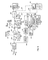
- FIG. 5 a circuit which in general consists of upper and lower functional paths for performing the COMP. RATE function and the TACH. function respectively.
- the input to the circuit is provided by a transducer designated T in FIG. 5 which may be any of the various units described above.
- the transducer signal is normally delivered on a coaxial cable as noted above, one side of the piezoelectric element being coupled to the outer conductive sheath 180 of the cable, while the other side of the piezoelectric element is connected to the central conductor 182 of the piezoelectric cable.
- the input signal from the transducer passes through the normally closed contacts of the switch 156 controlled by the CAL. pushbutton on the control panel. From the switch 156, the signal passes to the wiper arm 190 of a single pole-double throw switch controlled by the FILTER slideswitch 162 on the unit control panel.
- the switch 162 additionally controls a second single pole-double throw contact arm 192, the contact arms 190 and 192 being selectively actuable to connect a low pass filter circuit 194 into the input circuit path from the transducer for the purpose of removing all noise and other spurious signals outside of the primary signal band of approximately 0 -300 Hz.
- the filter 194 is optional and need not be used unless the transducer output signal exhibits a high level of unwanted high frequency component.
- the COMP. RATE channel includes a variable gain input amplifier consisting of an operational amplifier 198 operating in a non-inverting mode.
- the non-inverting input terminal (+) of the amplifier 198 receives its input signal through a pair of voltage dividing input resistors 200 and 202 and an input series resistor 204.
- a zener diode 206 acts as a reference voltage clamp to prevent spurious voltage spikes of an inordinately high magnitude from affecting the amplifier 198.
- Gain or sensitivity for the amplifier 198 is controlled by a plurality of feedback resistors 208, 210 and 212, respectively, selected for the negative feedback circuit of the amplifier 198 by the SENSIT.
- the output of the amplifier 198 passes through a diode 214 prior to being fed back through the resistors 208, 210 or 212.
- the diode 214 serves to limit current flow from the output of amplifier 198 to the forward direction only.
- a storage network 220 is selectively coupled to the output of the unidirectional amplifier 198 by the function selector switch 142 located on the operator's panel.
- the storage network includes a charging capacitor 222 coupled to ground and a discharge network connected in parallel with the capacitor 222 and including a resistor 224 of low value and the normally open reset (RST) pushbutton switch 148 located on the control panel.
- a digital readout circuit which consists of an A to D converter 226 for quantizing the signal and a driver and display circuit 228 which may be any of a plurality of known types capable of providing a numerical readout on the indicator 140.
- the A to D converter 226 serves to convert the output voltage signal from the storage network 220 to a numerically coded signal capable of being read on the numerical display 140.
- the "signal" may appear serially on a single output lead or as a parallel combination of binary digits on multiple lines provided for the respective digits.
- a pair of switches 230 and 232 at the input and output respectively of the storage network 220 serve to complete the circuit by assuming the closed position whenever the toggle lever 142 on the control panel is in the COMP. RATE position.
- the switch 142 additionally controls the actuation of one or the other of the pair of indicator lamps 144 or 146 designated, respectively, RPMX10 and COMP. RATE on the control panel.
- the RPMX10 indicator lamp 144 is connected between the positive supply and ground potentials in series with a single pole-single throw switch 240 which is closed whenever the function switch 142 is in the RPMX10 position.
- the COMP. RATE indicator lamp 146 is connected between the positive supply and ground potentials in series with a single pole-single throw switch 242 which is closed whenever the toggle lever 142 on the control panel is in its lower or COMP. RATE position.
- the transducer output signal is presented to the input voltage divider consisting of resistors 200 and 202.
- the resistors 200 and 202 are of a high value, typically in the range of 1 megohm or more so as to minimize loading on the piezoelectric element.
- the amplifier 198 passes the positive going portion of the transducer signal at a gain determined by the ratio of the feedback resistance to the input resistor 204, but due to the diode 214 the negative portion of the input signal from the transducer is inhibited. With the switch 230 closed the amplified positive half of the transducer signal rapidly charges the storage capacitor 222 to the peak magnitude of the scaled compression rate signal from the transducer.
- the capacitor 222 serves to hold a voltage corresponding to the maximum level achieved by the compression rate signal. This value is continuously monitored by the A to D converter circuit and manifested on the display 140 during operation in the COMP. RATE mode.
- the A to D circuit 226 is chosen to have a very high imput impedance so as to prevent discharge of the capacitor 222 therethrough.
- the COMP. RATE processing channel serves to store on the capacitor 222 a voltage corresponding to the maximum value of the transducer output signal at any given time after actuation of the RST pushbutton 148.
- a number corresponding to this maximum value is, accordingly, continuously displayed on the readout indicators 140, a slight reduction in the reading over a long time period being possible as a result of internal leakage of the capacitor 222 and slight leakage through the very high impedance components that flank the capacitor 222 in the circuit.
- the input signal from the transducer T is coupled to an operational amplifier 250 which acts as a high gain (open-loop) differential comparator.
- the reference voltage for the inverting input terminal of the amplifier 250 is supplied through a resistor 252 from the output of the unidirectional amplifier 198.
- the reference for the amplifier 250 is taken from this point to ensure that the amplifier 250 is only driven to a positive voltage output when the transducer signal exceeds a certain percentage of its peak average magnitude, it being presumed that the noise level of the transducer signal will not exceed that certain percentage of the peak value.
- the voltage dividing resistors 200 and 202 at the input of the amplifier 198 are typically made equal in value and the feedback resistor 208, 210 or 212 is chosen to be equal to the input resistor 204 so as to make the amplifier 198 essentially a unity gain amplifier.
- the diode 214 at the output of the amplifer 198 serves to make the amplifier operate only in the forward direction and the averaging function is performed by a parallel RC circuit consisting of a capacitor 256,and a resistor 258 referenced to ground potential.
- the time constant of the RC network 256 and 258 is chosen to be much faster than that of the storage network 220 by selection of a much smaller value for the capacitor 256 so that during the RPMX10 mode when the switch 230 is open, the reference voltage for the inverting input of the amplifier 250 can track up and down closely with changes in the magnitude of the transducer signal.
- the non-inverting input terminal of the operational amplifier 250 receives the transducer signal, filtered or unfiltered, through an input network consisting of a series resistor 262 and a shunt resistor 264 referenced to ground.
- a zener diode 266 in parallel with the resistor 264 prevents excessive voltage swings from occurring at the input to the amplifier 250.
- the operational amplifier 250 is biased in an open loop (i.e., no feedback) configuration and has extremely high gain. Thus, as the transducer signal at its non-inverting input terminal (+) exceeds the voltage level at its inverting input (-1 the output of the amplifier rises sharply toward the positive supply voltage.
- the TACH circuit For converting the output pulses from the amplifier 250 to an analog voltage level indicative of the frequency of those pulses the TACH circuit further includes a monostable multivibrator 270 and an integrator circuit 272.
- the monostable multivibrator 270 receives the output pulses from the amplifier 250 at its input terminals via a series resistor 274 and generates a pulse of constant width, typically of approximately 15 to 20 milliseconds, at the beginning or rising edge of each output pulse from the amplifier 250. This output pulse is positive-going with respect to ground and appears at the output Q of the monostable circuit 270.
- the inversion of this constant width pulse appears at the Q output of the monostable circuit 270 and is used to inhibit the input S of the monostable circuit during the period of the monostable so as to prevent false triggering from noise or spurious spikes that may occur at the output of the amplifier 250.
- the Q output is coupled to the base of a PNP type transistor 276 through a series resistor 278.
- the emitter of the transistor 276 is connected to the positive DC supply and the collector is coupled to ground through a dropping resistor 280.
- the output from the transistor 276 is taken from the collector thereof and is coupled to the S input terminal of the monostable circuit 270 through a diode 282.
- the transistor 276 is biased into conduction whenever the 5 output of the monostable circuit 27Q is at a low potential, thus clamping the input S of the monostable to a high voltage and inhibiting false triggering during the period of the pulse at the Q output of the circuit.
- the integrator circuit 272 has an RC input network consisting of a series resistor 286 and a shunt capacitor 288 coupled to ground.
- An operational amplifier 290 receives the input signal from the RC network at its non-inverting input terminal 291 and acts as a unity gain buffer by virtue of a direct feedback line 292 from its output back to its inverting (-) input.
- the output of the amplifier 290 is in turn connected to a second RC network consisting of a series resistor 294 and a capacitor 296 referenced to ground.
- the capacitor 296 is of a relatively high value compared to the capacitor 288 and acts as an integrator, the charging rate of the capacitor being governed by the series resistor 294 while its discharge is governed by a series resistive network consisting of a fixed resistor 297 and a variable resistor 298 connected in parallel with the capacitor 296.
- the value of the resistor 294 is chosen such that the voltage across the capacitor 296 can track normal increases in the speed of the engine being monitored.
- the voltage developed across the capacitor 296 is proportional to the frequency of the transducer signal and hence to engine speed.
- this voltage is coupled through the switch 232 to the analog to digital converter 226 where it is quantized to produce a binary coded numerical signal corresponding in numerical value to the voltage across the capacitor 296 and, hence, to speed. This, in turn, effects a reading on the panel display 140 which is indicative of engine speed.
- the tachometer portion of the system of FIG. 5 may be any of a variety of configurations without deviating from the scope of the present invention and may, for example, be of the type disclosed in pending application serial number 913,826 filed June 8, 1976 and assigned to Creative Tool.
- the tachometer circuit may be digital in nature and thus avoid the use of the analog integrator circuit 272. This, in turn, eliminates the need for the calibration oscillator on the panel control 158, thus simplifying the use of this device for the serviceman.
- FIG. 6 has features which even further simplify the use of the invention by the serviceman.
- means are provided for displaying the compression rate number and corresponding engine speeds simultaneously to simplify the recording function. This eliminates the need for the mode switch 142 and associated indicator lights 144 and 146 on the control panel.
- the embodiment of FIG. 6 utilizes a digital tachometer circuit, thus eliminating the need for the calibration adjustment 158 and pushbutton 156 on the control panel.
- a still further simplification is achieved by incorporating the low pass filter 194 shown in FIG.
- the embodiment of FIG. 6 includes a plurality of storage devices which allow the operator to store a voltage or number corresponding to the compression rate amplitude at each of a plurality of preselected speeds plus means for sequentially recalling or displaying the compression rate numbers for those selected speeds at the completion of a test cycle on a given cylinder.
- alternate memory and readout means are provided as an option in the system of FIG. 6 for use in more sophisticated or laboratory operations where long term storage and/or bulk storage is desirable and where printouts, or graphical compression rate curves are preferred.
- a three position switch including a wiper arm 310 controlled by a panel control knob 312 is provided in series with a selected one of a group of resistors 314, 316 and 318 referenced to ground.
- the signal reaching the non-inverting input terminal of the amplifier 198a may be greater or less, as desired, to ensure that operation of the system throughout the test is within the limits of the output display.
- the operational amplifier 198a is shown in a unity-gain configuration, although it will be appreciated that gain may be added to the system, as desired, by providing resistors in series with the non-inverting input terminal C+) and in the feedback line between the cathode of the diode 214a and the inverting input terminal (-1, the gain being dependent upon the ratio of the feedback resistor to the input resistor. Due to the high reverse impedance of the steering diode 214a, the maximum voltage achieved at the output of the amplifier 198a during the positive half cycle of the transducer output signal is stored in the capacitor circuit 222a until discharge is effected by the reset button designated 148a and provided on the control panel.
- the capacitor 222 shown in FIG. 5 is replaced in the present embodiment of FIG. 6 by a plurality of capacitors 320, 322, 324 and 326 which are of relatively high value (typically 100 microfarads) to provide long persistence and low leakage for the signals being stored. Selection from among these capacitors for operation in the circuit is achieved via a four position rotary switch which includes a wiper arm 330 under the control of a panel knob 332.
- the knob 332 is designated CR MEMORY and includes positions for various speeds (RPM) at which the scaled compression rate signal is to be measured and stored. In a typical operating sequence, the operator progressively raises the speed of the engine and monitors that speed through the tachometer readout to be described.
- the reset button 148a may be used by the operator at each of the aforesaid sampling speeds to momentarily discharge the operative capacitor from among the group 320, 322, 324 and 326 to ensure that the maximum compression rate signal is stored only when the speed is stabilized at the selected level and that a value has not been stored that may have resulted from a temporary overshoot of the selected speed, it being recalled that the voltage stored in the capacitor bank 228 can only track the compression rate in a positive direction and will only increase until the RST button 148a is pushed.
- the compression rate channel may include, in lieu of the analog storage bank consisting of the capacitor 222a, a digital memory and microprocessor circuit 336 coupled with an appropriate readout device 338.
- the memory 336 preferably receives the compression rate signal after it has been converted to a numerically coded binary number at the output of the A to D converter 226a via one or more data lines functionally represented by a broken line 339.
- successive values for both the quantized maximum compression rate and the quantized corresponding speeds can be recorded at any desired interval.
- the capacitive storage bank 222a which is typically a single capacitor when used with the digital memory 336, upon the completion of each recording operation by the memory and processor circuit 336.
- the resetting of the aforesaid capacitive storage device is functionally denoted by a broken line 340 operating upon the RST button 148a under the control of the memory and processor, although it will be appreciated that resetting of the capacitive device is preferably accomplished by a solid state switch connected in parallel with the capacitive storage device 222 or 222a and adapted to be closed by an appropriate digital signal or pulse developed by the memory and processor circuit 336 at the end of its storage function.
- FIG. 6 illustrates a digital tachometer circuit which may be used in lieu of the combination analog-digital circuit shown in FIG. 5.
- the filtered transducer pulses are fed to a threshold detector 344 which serves to create an output pulse only for those portions of the transducer pulses which exceed a predetermined level above the ambient noise. Since the signals developed from the transducer are of relatively low frequency, a frequency multiplier 346 is provided at the output of the threshold detector to provide a train of pulses which occur at a rate proportional to the transducer output signal but at a rate which is preferably several orders of magnitude in excess of that of the transducer pulses.
- the frequency mulitplier 346 may be any of a variety of circuits known to the art, one example being a voltage controlled oscillator driven by a frequency to voltage converter.
- the frequency-multiplied transducer pulses are then fed to a counter 348 in serial fashion via the clock input C thereto.
- the counter 348 may be any of a plurality of commonly available digital counters of the ripple or other type having a terminal provided for resetting the counter to zero in response to an applied pulse.
- the counter 348 is typically a multistage device having a plurality of parallel outputs 350a-n which register a number in binary coded decimal form. For the purpose of selectively sampling the number in the counter and storing that number for readout purposes, a multistage latch circuit 352 is provided.
- the latch circuit 352 has successive memory stages corresponding to the outputs from the counter 348 and is adapted to accept and hold the binary digits from the counter 348 in those latch stages upon the rising edge of a pulse applied to an input 354 designated ENABLE.
- the pulse to the ENABLE input 354 of the latch circuit 352 is provided by a sample pulse generator 356 which operates at a constant frequency to produce a narrow pulse shown in a circle E.
- the output pulse from the sample pulse generator 356 is also applied to the reset terminal R of the counter 348, the small circle at the reset terminal R signifying that the counter is reset on the trailing edge of the sample pulse from the generator 356.
- the width of the sample pulse is preferably less than the minimum period between pulses from the frequency multiplier 346 so that sampling by the latch 352 and resetting of the counter 348 can occur without significantly affecting the accuracy of the counting function.
- the duration between successive pulses from the sample pulse generator 356 is established such that the binary coded decimal (BCD) number accumulated by the counter 348 prior to sampling corresponds to the speed or RPM of the engine at all times.
- BCD binary coded decimal
- the choice of multipliers for the frequency multiplier circuit 346 and the size of the counter 348 is governed by the same consideration. The higher the multiplier chosen for the circuit 346, the faster sampling by the latch circuit 352 may occur.
- the output of the latch circuit 352 is provided on the series of lines 360a-n which in turn are coupled through a BCD-to-decimal converter circuit 363 which may be any of a variety of circuits commercially available for this function.
- the output of the converter circuit 363, in turn, is provided on a series of lines 365a through 365m which are coupled to a suitable driver and RPM display circuit 367.
- the circuit 367 illuminates a plurality of numerical readout elements 140b provided on the face of the control panel to indicate to the operator the then existing speed of the engine.
- the suffixes n and m for the output lines 350, 360 and 365 are used to signify that the number of lines in each instance is variable depending upon the size of the chosen counter 348, latch 352 and converter circuits 363.
- the speed- indicative digital number in the BCD to decimal, converter circuit 363 is also applied to the memory and.processor circuit 336 in the instance where the digital memory and readout units 336 and 338 are utilized.
- This optional connection is functionally depicted by a broken line 370 from the converter circuit 363 to the memory and processor circuit 336.
- the speed-related information for the memory and processor circuit 336 may also be taken from the output of the latch device 352 rather than the converter circuit 363.
- low frequency pulses from the transducer T pass through the filter 194a to the threshold detector 344 and create a pulse train which is still at relatively low frequency.
- This pulse train is multiplied in frequency by several orders of magnitude by the multiplier 346 and thereafter applied to the counter circuit 348.
- a narrow pulse is generated by the circuit 356 which first enables the latch circuit 352 to register the number then contained in the counter 348.
- the counter is reset to zero, with the last registered count being stored in the latch circuit 352.
- the number in the latch circuit 352 is continuously converted to decimal notation by the circuit 363 and displayed on the readout 140b, that number being successively updated upon the occurrence of each sample pulse from the circuit 356.
- the memory and processor circuit 336 stores a plurality of quantized compression rates for various speeds of the engine.
- the readout circuit 338 may, for example, be in the form of a printer capable of printing out the quantized compression rates in a serial form with their corresponding speeds or in a graph form with speed as the abscissa and quantized compression rate as the ordinate.
- the processor 336 may also be used to compute ratios of one quantized compression rate number to another and to read out or graph those ratios automatically.
- the microprocessor may be used to print out or otherwise indicate through the readout device 338 deviations from the norm by each cylinder, or in less demanding environments, to provide a fault indication (a light, buzzer or the like) to the operator whenever the compression rate for a given cylinder deviates from the norm by more than a predetermined amount.
- the quantized compression rate signals and readout developed by the system may also be used as an on-board monitoring device installed in the vehicle dash and used in a manner similar to a vaccuum gauge or the like.
- the compression rate signal taken from the transducers herein disclosed increases in amplitude as the temperature of the engine increases. This phenomenon can be readily ascertained with the apparatus herein described and monitoring of this increase is useful in analyzing overall engine performance, fuel economy and emissions during warm-up conditions, since it is known that fuel flow, atomization and actual cylinder pressure all vary with temperature during warm-up.
- the analyzer of the present invention may be used, for example, to monitor the manner in which changes in fuel content, humidity and other external factors affect the engine during warm-up.
- compression rate or “compression rate signal” as used herein refer to the output or output signals of the type produced by certain piezoelectric transducers when coupled to or used in place of various engine components which extend into the cylinder combustion chamber.
- This signal at least for frequencies in the range of normal engine speeds, exhibits the characteristics of the first derivative or time-rate-of-change of the actual pressure within the observed engine cylinder. As such, it does not reflect the steady state pressure to which it is subjected in its attachment to the engine but rather is reflective of the manner in which pressure changes within the cylinder.
- quantizing or “quantized” as used herein are used in their conventional sense to denote the conversion of a physical attribute the amplitude or magnitude of a signal into a corresponding numerical value.
- a malfunction occurring in one or more cylinders is detected by comparing the compression rate readings taken from each of the cylinders by the same transducer during normal operation of the engine at a given speed. A reading lower than the norm by 15% or more is indicative of a malfunction in the corresponding cylinder. If the misfiring or other engine problem manifests itself only at elevated engine speeds, the operator may record the pressure rate of change readings from each of the cylinders at a plurality of predetermined speeds. Again, the faulty cylinder is located by comparing the readings taken from each cylinder to the norm.
- the problem with that cylinder may be further diagnosed by various methods.
- a second set of readings of the quantized compression rate, as measured by the same transducer attached to the cylinder, can be taken with the fuel line for that cylinder disconnected at the injector nozzle or at the injector pump. If the quantized compression rate reading at a given speed is not significantly lower than it was at the same speed with the fuel line connected, the combustion component of the transducer signal is not present and the injector nozzle is likely to be at fault and should be repaired or replaced.
- the quantized compression rate reading for the suspected cylinder with the fuel line disconnected does not conform to the reading obtained with the fuel line connected, the fuel line for a second cylinder is disconnected and the transducer is moved to that second cylinder. Readings of the quantized compression rate for the second cylinder are then taken at the same speeds as for the suspect cylinder. If, at given identical speeds, the readings for both cylinders with the fuel lines disconnected are approximately the same, then the variation in compression rate readings between the two cylinders in normal operation with the fuel system attached can be attributed to the faulty injector system for the suspect cylinder.
- the compression rate readings for the suspect cylinder fall substantially below those for other cylinders when the fuel lines for each are disconnected, then the malfunction of the suspect cylinder can be attributed to cylinder components other than the injector system, such as the valves, rings, piston, etc.
- an overhaul may be dictated by this finding, that overhaul may be limited to the suspect cylinder, thus effecting a substantial saving in time and expense.
- the compression rate for each cylinder may be taken from the same plug transducer of the type disclosed in U.S. application serial number 007,347 while the distributor lead to each plug is connected. This is done by loosening or removing each plug in succession and retightening the plug into position with the transducer attached. Compression rate readings from all cylinders are recorded for one or more preselected speeds. A reading lower than the norm by 15% or more signals a malfunction in the cylinder producing that reading.
- the plug can be considered at least partially operative and a further comparison may be desirable.
- the spark plug wires for the suspect plug and a second, and preferably normal, plug are removed in succession and compression rate readings for each of the cylinders are taken from the same transducer at the same speeds.
- Significant variations of the compression rate signals under this no-firing condition are indicative of non-electrical malfunctions in the cylinder providing the lower readings, such malfunctions being attributable to bad rings, valves, pistons or the like.
- the compression rates for the various cylinders of the carbureted engine are preferably recorded and compared for a plurality of engine speeds, since the malfunctions associated with carbureted engines often manifest themselves in only a portion of the speed range.
- the apparatus of the present invention Still a further method of diagnosis is possible with the apparatus of the present invention.
- the nozzles or glow plugs are hard to reach or are irregular in other manners due to their location, size, seating surface or the like.
- the same approximate torque cannot be applied to the transducer when it is applied to each of the cylinders.
- the operator for each cylinder, first records the compression rate for one or more speeds (typically 700, 1000, 1500 and 2000 RMP) with the fuel line to the injector nozzle for that cylinder disconnected.
- the compression rate readings at the same speeds are taken with the fuel line reconnected (or spark plug wire reconnected in the carbureted enginel.
- the ratio of compression rate without injection to compression rate with injection, CRw/ CRi is calculated for each of the various speeds and compared cylinder to cylinder. Again, a deviation in this ratio from the norm by more than 10-15% is indicative of a malfunctioning cylinder. Since the absolute value of both the numerator and denominator of this ratio are equally affected by the manner in which the transducer is coupled to the cylinder, the variations in this ratio from cylinder to cylinder are attributable solely to the performance or failures of the injector system. Those cylinders for which this ratio deviates substantially from the norm are thus isolated as probably malfunctioning and corrections can be made to the fuel carrying components for that cylinder.
- the compression rate numbers for one or more cylinders may be monitored at cranking speed with the fuel pump, and hence the entire injection system, disabled. This test may be conducted by itself or in conjunction with one or more of the methods disclosed above.
- the same transducer is preferably moved from cylinder to cylinder. Readings of compression rate are taken from each cylinder with the temperature of the engine at or substantially near the same level in each instance. This can be done with the engine cold, but in most instances the engine will have been warmed to normal operating temperature and stabilized. The latter condition is preferable since cranking speed is more likely to remain constant if the electrical system is fully charged, a condition which is more likely to exist in a fully warmed-up engine.
Landscapes
- Engineering & Computer Science (AREA)
- Chemical & Material Sciences (AREA)
- Combustion & Propulsion (AREA)
- Physics & Mathematics (AREA)
- General Physics & Mathematics (AREA)
- Mechanical Engineering (AREA)
- General Engineering & Computer Science (AREA)
- Measuring Fluid Pressure (AREA)
- Testing Of Engines (AREA)
Applications Claiming Priority (2)
| Application Number | Priority Date | Filing Date | Title |
|---|---|---|---|
| US56501 | 1979-07-11 | ||
| US06/056,501 US4292841A (en) | 1979-07-11 | 1979-07-11 | Compression rate analyzer |
Publications (1)
| Publication Number | Publication Date |
|---|---|
| EP0022565A1 true EP0022565A1 (de) | 1981-01-21 |
Family
ID=22004814
Family Applications (1)
| Application Number | Title | Priority Date | Filing Date |
|---|---|---|---|
| EP80103975A Withdrawn EP0022565A1 (de) | 1979-07-11 | 1980-07-10 | Kompressionsverhältnisanalysator |
Country Status (3)
| Country | Link |
|---|---|
| US (1) | US4292841A (de) |
| EP (1) | EP0022565A1 (de) |
| JP (1) | JPS5669533A (de) |
Cited By (7)
| Publication number | Priority date | Publication date | Assignee | Title |
|---|---|---|---|---|
| GB2160324A (en) * | 1984-06-11 | 1985-12-18 | William B Alexander | Device for testing physical parameters of an object |
| AU570623B2 (en) * | 1981-08-21 | 1988-03-24 | Harris Corporation | Engine monitoring system |
| AU579348B2 (en) * | 1984-02-21 | 1988-11-24 | Ingemar Eriksson | A method and a device for testing the tightness of an engine |
| RU2347203C1 (ru) * | 2007-05-28 | 2009-02-20 | Рязанский военный автомобильный институт имени генерала армии В.П. ДУБЫНИНА | Анализатор работы систем двигателя внутреннего сгорания |
| EP2071166A3 (de) * | 2007-12-11 | 2012-02-29 | ThyssenKrupp Krause GmbH | Verfahren zum Prüfen eines Verbrennungsmotors |
| CN103592130A (zh) * | 2013-11-15 | 2014-02-19 | 中航飞机股份有限公司西安飞机分公司 | 一种飞机发动机吸力供油地面模拟试验方法 |
| RU2532990C2 (ru) * | 2011-01-11 | 2014-11-20 | Федеральное государственное военное образовательное учреждение высшего профессионального образования "Военный учебно-научный центр Сухопутных войск Общевойсковая академия Вооруженных Сил Российской Федерации" | Анализатор работы систем двигателя внутреннего сгорания |
Families Citing this family (22)
| Publication number | Priority date | Publication date | Assignee | Title |
|---|---|---|---|---|
| US4567751A (en) * | 1982-10-07 | 1986-02-04 | Nippon Soken, Inc. | Knocking detection device in diesel engine |
| US4517833A (en) * | 1983-03-18 | 1985-05-21 | Wesley William M | Inductive adaptor/generator for diesel engines |
| EP0140082B1 (de) * | 1983-10-05 | 1989-08-16 | Robert Bosch Gmbh | Elektronische Schaltungsanordnung zur Umwandlung der Dauer eines Pulses in eine proportionale Spannung |
| US5038893A (en) * | 1989-09-25 | 1991-08-13 | Orsco, Inc. | Lubrication monitoring system |
| CA2081080C (en) * | 1992-10-23 | 1998-08-11 | Philippe Gaultier | Method for the detection of reciprocating machine faults and failures |
| US5359883A (en) * | 1993-08-16 | 1994-11-01 | Caterpillar Inc. | Apparatus and method for analyzing events for an internal combustion engine |
| US5581016A (en) * | 1994-11-29 | 1996-12-03 | The Cessna Aircraft Company | Aircraft engine detonation indication system |
| US5918275A (en) * | 1996-03-26 | 1999-06-29 | Sanshin Kogyo Kabushiki Kaisha | Sensor for engine control |
| US5756888A (en) * | 1997-03-20 | 1998-05-26 | Marquez-Escoto; Jose G. | Compression stroke indicator |
| TW513833B (en) * | 1998-09-09 | 2002-12-11 | Honda Motor Co Ltd | Mounting method of sparking plug cap and sparking plug cap |
| US6055852A (en) * | 1998-11-06 | 2000-05-02 | Cummins Engine Company, Inc. | Method and apparatus for estimation of relative cylinder compression balance by cranking speed analysis |
| US6516658B1 (en) | 1999-04-16 | 2003-02-11 | Siemens Vdo Automotive Corporation | Identification of diesel engine injector characteristics |
| US6836224B1 (en) * | 1999-11-01 | 2004-12-28 | Siemens Vdo Automotive Corporation | Method for assigning coded incremental values |
| US6416036B2 (en) * | 2000-01-31 | 2002-07-09 | Teijin Limited | Sealing arrangement between flow regulator and shut-off valve attached to oxygen cylinder |
| US6609416B2 (en) * | 2002-01-16 | 2003-08-26 | Senx Technologies, Llc | Diagnostic devices for internal combustion engines and systems for their use |
| US6859763B2 (en) * | 2002-02-15 | 2005-02-22 | General Motors Corporation | Technique for computing a measure on an ultrasonic signal having application to identify valve defects in operating engines |
| US7449994B1 (en) * | 2004-02-06 | 2008-11-11 | Brp Us Inc. | Engine mounted fault indicators |
| RU2268459C1 (ru) * | 2004-03-16 | 2006-01-20 | Василий Николаевич Хабардин | Компрессометр с беспружинным клапаном |
| ES2261071B1 (es) * | 2005-04-01 | 2007-11-16 | Vicente Blazquez Navarro | Sistema de monitorizacion de comprension en motores alternativos de explosion. |
| FR2927420B1 (fr) * | 2008-02-13 | 2010-02-26 | Continental Automotive France | Dispositif de mesure de pression et procede correspondant |
| US9279406B2 (en) | 2012-06-22 | 2016-03-08 | Illinois Tool Works, Inc. | System and method for analyzing carbon build up in an engine |
| US10208651B2 (en) * | 2016-02-06 | 2019-02-19 | Prometheus Applied Technologies, Llc | Lean-burn pre-combustion chamber |
Citations (7)
| Publication number | Priority date | Publication date | Assignee | Title |
|---|---|---|---|---|
| US3183708A (en) * | 1961-10-12 | 1965-05-18 | Shell Oil Co | Method and apparatus for metering pressure phenomena in internal combustion engines |
| US3576526A (en) * | 1966-08-26 | 1971-04-27 | British Petroleum Co | Detection of knock in internal combustion engines |
| US4036050A (en) * | 1976-03-24 | 1977-07-19 | Dooley Joseph L | Engine monitoring apparatus |
| US4109518A (en) * | 1976-03-24 | 1978-08-29 | Creative Tool Company | Engine monitoring apparatus |
| GB2009406A (en) * | 1977-12-06 | 1979-06-13 | Snam Progetti | Detecting knocking in an engine |
| DE2916591A1 (de) * | 1978-04-24 | 1979-10-25 | Nippon Soken | Verfahren und vorrichtung zur feststellung des klopfens von brennkraftmaschinen |
| DE2917213A1 (de) * | 1978-05-01 | 1979-11-08 | Nissan Motor | Vorrichtung zum ermitteln der staerke des klopfens einer brennkraftmaschine |
Family Cites Families (1)
| Publication number | Priority date | Publication date | Assignee | Title |
|---|---|---|---|---|
| US4131014A (en) * | 1977-06-07 | 1978-12-26 | Caterpillar Tractor Co. | Dynamic timing indicating apparatus |
-
1979
- 1979-07-11 US US06/056,501 patent/US4292841A/en not_active Expired - Lifetime
-
1980
- 1980-07-10 EP EP80103975A patent/EP0022565A1/de not_active Withdrawn
- 1980-07-11 JP JP9408480A patent/JPS5669533A/ja active Pending
Patent Citations (7)
| Publication number | Priority date | Publication date | Assignee | Title |
|---|---|---|---|---|
| US3183708A (en) * | 1961-10-12 | 1965-05-18 | Shell Oil Co | Method and apparatus for metering pressure phenomena in internal combustion engines |
| US3576526A (en) * | 1966-08-26 | 1971-04-27 | British Petroleum Co | Detection of knock in internal combustion engines |
| US4036050A (en) * | 1976-03-24 | 1977-07-19 | Dooley Joseph L | Engine monitoring apparatus |
| US4109518A (en) * | 1976-03-24 | 1978-08-29 | Creative Tool Company | Engine monitoring apparatus |
| GB2009406A (en) * | 1977-12-06 | 1979-06-13 | Snam Progetti | Detecting knocking in an engine |
| DE2916591A1 (de) * | 1978-04-24 | 1979-10-25 | Nippon Soken | Verfahren und vorrichtung zur feststellung des klopfens von brennkraftmaschinen |
| DE2917213A1 (de) * | 1978-05-01 | 1979-11-08 | Nissan Motor | Vorrichtung zum ermitteln der staerke des klopfens einer brennkraftmaschine |
Cited By (8)
| Publication number | Priority date | Publication date | Assignee | Title |
|---|---|---|---|---|
| AU570623B2 (en) * | 1981-08-21 | 1988-03-24 | Harris Corporation | Engine monitoring system |
| AU579348B2 (en) * | 1984-02-21 | 1988-11-24 | Ingemar Eriksson | A method and a device for testing the tightness of an engine |
| GB2160324A (en) * | 1984-06-11 | 1985-12-18 | William B Alexander | Device for testing physical parameters of an object |
| US4642783A (en) * | 1984-06-11 | 1987-02-10 | Safe-Test, Inc. | Life raft testing device |
| RU2347203C1 (ru) * | 2007-05-28 | 2009-02-20 | Рязанский военный автомобильный институт имени генерала армии В.П. ДУБЫНИНА | Анализатор работы систем двигателя внутреннего сгорания |
| EP2071166A3 (de) * | 2007-12-11 | 2012-02-29 | ThyssenKrupp Krause GmbH | Verfahren zum Prüfen eines Verbrennungsmotors |
| RU2532990C2 (ru) * | 2011-01-11 | 2014-11-20 | Федеральное государственное военное образовательное учреждение высшего профессионального образования "Военный учебно-научный центр Сухопутных войск Общевойсковая академия Вооруженных Сил Российской Федерации" | Анализатор работы систем двигателя внутреннего сгорания |
| CN103592130A (zh) * | 2013-11-15 | 2014-02-19 | 中航飞机股份有限公司西安飞机分公司 | 一种飞机发动机吸力供油地面模拟试验方法 |
Also Published As
| Publication number | Publication date |
|---|---|
| JPS5669533A (en) | 1981-06-10 |
| US4292841A (en) | 1981-10-06 |
Similar Documents
| Publication | Publication Date | Title |
|---|---|---|
| US4292841A (en) | Compression rate analyzer | |
| US4684896A (en) | Testing method for ignition systems of internal combustion engines in motor vehicles | |
| EP0396665B1 (de) | Leistungsmessanordnung | |
| US5585552A (en) | Method and apparatus for diagnosing automotive engine problems using oxygen | |
| US4006403A (en) | Engine performance analyzer | |
| US5041976A (en) | Diagnostic system using pattern recognition for electronic automotive control systems | |
| CA1165442A (en) | Method and apparatus for measurement of engine ignition timing | |
| US4518268A (en) | Diesel engine diagnostic system | |
| JPH0587036A (ja) | 燃焼状態診断装置 | |
| US3839906A (en) | Apparatus for engine compression testing | |
| US4036050A (en) | Engine monitoring apparatus | |
| US4328546A (en) | Apparatus for evaluating the performance of an internal combustion engine using exhaust gas emission data | |
| US20100030446A1 (en) | Indexing system and method for determining an engine parameter | |
| US3955135A (en) | Vehicle rpm and dwell measurement system | |
| US3986009A (en) | Power contribution measurement system for internal combustion engines | |
| US5132909A (en) | Apparatus for diagnosing individual cylinder performance by estimated instantaneous engine speeds | |
| US4185494A (en) | Diagnostic system for fuel injected engines | |
| US4062232A (en) | Testing compression in engines from starter motor current waveform | |
| EP0715160B1 (de) | Klopfanzeigesystem für Brennkraftmaschine | |
| US4523458A (en) | Injector tester | |
| JP2807737B2 (ja) | 内燃エンジンの燃焼状態検出装置 | |
| US5585717A (en) | Method for measuring starter motor current to determine engine status | |
| US6917875B2 (en) | Method and apparatus for processing and display of diesel injection waveform | |
| US3961239A (en) | Signal conditioning circuit for vehicle diagnostic system | |
| US4423624A (en) | Diesel timing light |
Legal Events
| Date | Code | Title | Description |
|---|---|---|---|
| PUAI | Public reference made under article 153(3) epc to a published international application that has entered the european phase |
Free format text: ORIGINAL CODE: 0009012 |
|
| AK | Designated contracting states |
Designated state(s): DE FR GB |
|
| STAA | Information on the status of an ep patent application or granted ep patent |
Free format text: STATUS: THE APPLICATION IS DEEMED TO BE WITHDRAWN |
|
| 18D | Application deemed to be withdrawn |
Effective date: 19811228 |
|
| RIN1 | Information on inventor provided before grant (corrected) |
Inventor name: WESLEY, WILLIAM M. |