EP0024949A2 - Apparatus and method for spray metallizing a corrodible metal substrate with a protective metal - Google Patents
Apparatus and method for spray metallizing a corrodible metal substrate with a protective metal Download PDFInfo
- Publication number
- EP0024949A2 EP0024949A2 EP80303076A EP80303076A EP0024949A2 EP 0024949 A2 EP0024949 A2 EP 0024949A2 EP 80303076 A EP80303076 A EP 80303076A EP 80303076 A EP80303076 A EP 80303076A EP 0024949 A2 EP0024949 A2 EP 0024949A2
- Authority
- EP
- European Patent Office
- Prior art keywords
- molten metal
- substrate
- metal
- nozzle
- point
- Prior art date
- Legal status (The legal status is an assumption and is not a legal conclusion. Google has not performed a legal analysis and makes no representation as to the accuracy of the status listed.)
- Granted
Links
- 229910052751 metal Inorganic materials 0.000 title claims abstract description 79
- 239000002184 metal Substances 0.000 title claims abstract description 79
- 239000000758 substrate Substances 0.000 title claims abstract description 39
- 238000000034 method Methods 0.000 title claims abstract description 26
- 239000007921 spray Substances 0.000 title claims abstract description 20
- 230000001681 protective effect Effects 0.000 title description 2
- 239000011248 coating agent Substances 0.000 claims abstract description 36
- 238000000576 coating method Methods 0.000 claims abstract description 36
- HCHKCACWOHOZIP-UHFFFAOYSA-N Zinc Chemical compound [Zn] HCHKCACWOHOZIP-UHFFFAOYSA-N 0.000 claims abstract description 27
- 229910052725 zinc Inorganic materials 0.000 claims abstract description 25
- 239000011701 zinc Substances 0.000 claims abstract description 25
- 229910000831 Steel Inorganic materials 0.000 claims abstract description 12
- 239000010959 steel Substances 0.000 claims abstract description 12
- 238000010891 electric arc Methods 0.000 claims abstract description 9
- 238000002844 melting Methods 0.000 claims abstract description 6
- 230000008018 melting Effects 0.000 claims abstract description 6
- 239000002245 particle Substances 0.000 claims abstract description 6
- PXHVJJICTQNCMI-UHFFFAOYSA-N Nickel Chemical compound [Ni] PXHVJJICTQNCMI-UHFFFAOYSA-N 0.000 claims description 6
- 229910052782 aluminium Inorganic materials 0.000 claims description 5
- XAGFODPZIPBFFR-UHFFFAOYSA-N aluminium Chemical compound [Al] XAGFODPZIPBFFR-UHFFFAOYSA-N 0.000 claims description 5
- 239000004020 conductor Substances 0.000 claims description 4
- 229910045601 alloy Inorganic materials 0.000 claims description 3
- 239000000956 alloy Substances 0.000 claims description 3
- 239000000919 ceramic Substances 0.000 claims description 3
- 229910052759 nickel Inorganic materials 0.000 claims description 3
- 239000010935 stainless steel Substances 0.000 claims description 3
- 229910001220 stainless steel Inorganic materials 0.000 claims description 3
- 239000004411 aluminium Substances 0.000 claims 2
- 229910010293 ceramic material Inorganic materials 0.000 claims 1
- 239000010953 base metal Substances 0.000 abstract description 6
- 239000007789 gas Substances 0.000 description 14
- 229910001338 liquidmetal Inorganic materials 0.000 description 6
- 239000003570 air Substances 0.000 description 5
- 239000000463 material Substances 0.000 description 5
- 150000002739 metals Chemical class 0.000 description 4
- OKTJSMMVPCPJKN-UHFFFAOYSA-N Carbon Chemical compound [C] OKTJSMMVPCPJKN-UHFFFAOYSA-N 0.000 description 3
- 238000005422 blasting Methods 0.000 description 3
- TWNQGVIAIRXVLR-UHFFFAOYSA-N oxo(oxoalumanyloxy)alumane Chemical compound O=[Al]O[Al]=O TWNQGVIAIRXVLR-UHFFFAOYSA-N 0.000 description 3
- 238000005299 abrasion Methods 0.000 description 2
- 230000000712 assembly Effects 0.000 description 2
- 238000000429 assembly Methods 0.000 description 2
- 230000007812 deficiency Effects 0.000 description 2
- 238000010586 diagram Methods 0.000 description 2
- 238000005246 galvanizing Methods 0.000 description 2
- 229910002804 graphite Inorganic materials 0.000 description 2
- 239000010439 graphite Substances 0.000 description 2
- 239000007788 liquid Substances 0.000 description 2
- 239000000843 powder Substances 0.000 description 2
- 239000007787 solid Substances 0.000 description 2
- 239000000126 substance Substances 0.000 description 2
- 238000007751 thermal spraying Methods 0.000 description 2
- 238000003466 welding Methods 0.000 description 2
- 239000004215 Carbon black (E152) Substances 0.000 description 1
- 229910001018 Cast iron Inorganic materials 0.000 description 1
- RYGMFSIKBFXOCR-UHFFFAOYSA-N Copper Chemical compound [Cu] RYGMFSIKBFXOCR-UHFFFAOYSA-N 0.000 description 1
- QAOWNCQODCNURD-UHFFFAOYSA-N Sulfuric acid Chemical compound OS(O)(=O)=O QAOWNCQODCNURD-UHFFFAOYSA-N 0.000 description 1
- 239000012080 ambient air Substances 0.000 description 1
- 229910052799 carbon Inorganic materials 0.000 description 1
- 238000004140 cleaning Methods 0.000 description 1
- 238000010276 construction Methods 0.000 description 1
- 238000011109 contamination Methods 0.000 description 1
- 238000007796 conventional method Methods 0.000 description 1
- 229910052802 copper Inorganic materials 0.000 description 1
- 239000010949 copper Substances 0.000 description 1
- 238000005238 degreasing Methods 0.000 description 1
- 238000007598 dipping method Methods 0.000 description 1
- 238000005553 drilling Methods 0.000 description 1
- 239000012777 electrically insulating material Substances 0.000 description 1
- 230000005484 gravity Effects 0.000 description 1
- 229930195733 hydrocarbon Natural products 0.000 description 1
- 150000002430 hydrocarbons Chemical class 0.000 description 1
- KFZAUHNPPZCSCR-UHFFFAOYSA-N iron zinc Chemical compound [Fe].[Zn] KFZAUHNPPZCSCR-UHFFFAOYSA-N 0.000 description 1
- 238000004519 manufacturing process Methods 0.000 description 1
- 239000000155 melt Substances 0.000 description 1
- 239000013528 metallic particle Substances 0.000 description 1
- 239000003973 paint Substances 0.000 description 1
- 235000021110 pickles Nutrition 0.000 description 1
- 238000002360 preparation method Methods 0.000 description 1
- 239000003380 propellant Substances 0.000 description 1
- 239000002893 slag Substances 0.000 description 1
- 235000011149 sulphuric acid Nutrition 0.000 description 1
- 239000001117 sulphuric acid Substances 0.000 description 1
- 239000002699 waste material Substances 0.000 description 1
Images



Classifications
-
- B—PERFORMING OPERATIONS; TRANSPORTING
- B05—SPRAYING OR ATOMISING IN GENERAL; APPLYING FLUENT MATERIALS TO SURFACES, IN GENERAL
- B05B—SPRAYING APPARATUS; ATOMISING APPARATUS; NOZZLES
- B05B7/00—Spraying apparatus for discharge of liquids or other fluent materials from two or more sources, e.g. of liquid and air, of powder and gas
- B05B7/16—Spraying apparatus for discharge of liquids or other fluent materials from two or more sources, e.g. of liquid and air, of powder and gas incorporating means for heating or cooling the material to be sprayed
- B05B7/22—Spraying apparatus for discharge of liquids or other fluent materials from two or more sources, e.g. of liquid and air, of powder and gas incorporating means for heating or cooling the material to be sprayed electrically, magnetically or electromagnetically, e.g. by arc
- B05B7/222—Spraying apparatus for discharge of liquids or other fluent materials from two or more sources, e.g. of liquid and air, of powder and gas incorporating means for heating or cooling the material to be sprayed electrically, magnetically or electromagnetically, e.g. by arc using an arc
-
- C—CHEMISTRY; METALLURGY
- C23—COATING METALLIC MATERIAL; COATING MATERIAL WITH METALLIC MATERIAL; CHEMICAL SURFACE TREATMENT; DIFFUSION TREATMENT OF METALLIC MATERIAL; COATING BY VACUUM EVAPORATION, BY SPUTTERING, BY ION IMPLANTATION OR BY CHEMICAL VAPOUR DEPOSITION, IN GENERAL; INHIBITING CORROSION OF METALLIC MATERIAL OR INCRUSTATION IN GENERAL
- C23C—COATING METALLIC MATERIAL; COATING MATERIAL WITH METALLIC MATERIAL; SURFACE TREATMENT OF METALLIC MATERIAL BY DIFFUSION INTO THE SURFACE, BY CHEMICAL CONVERSION OR SUBSTITUTION; COATING BY VACUUM EVAPORATION, BY SPUTTERING, BY ION IMPLANTATION OR BY CHEMICAL VAPOUR DEPOSITION, IN GENERAL
- C23C4/00—Coating by spraying the coating material in the molten state, e.g. by flame, plasma or electric discharge
- C23C4/12—Coating by spraying the coating material in the molten state, e.g. by flame, plasma or electric discharge characterised by the method of spraying
- C23C4/123—Spraying molten metal
Definitions
- This invention relates to a method and apparatus for coating a corrodible base metal, on one or both sides, with another metal which is molten. More particularly, the invention relates to a method and apparatus for spray metallizing a coating of metal onto one side of the metal, using an electric arc.
- a number of processes are known for the production of sheet steel which is galvanized on one side. These include such conventional methods as the continuous passage of sheet metal through a bath of molten metal, and continuous thermal spraying.
- Commercial galvanized sheet in which zinc is coated on both sides is not generally acceptable for use in automobile body construction because of complications arising from the adherence of zinc to the tips of welding electrodes in resistance welding processes.
- it is desirable to have the zinc covering on interior surfaces where its protective qualities are most needed it is desirable to leave the exterior surfaces uncoated to promote the adherence of paint or other surface finishes.
- the material being sprayed in this case zinc, is supplied to "pot guns" in bulk form and heated to a temperature of approximately 426-482° C., and atomized with a propellant such as air and sprayed onto the surface to be coated.
- a propellant such as air and sprayed onto the surface to be coated.
- wire or powder is fed into an oxy-fueled flame which melts it and air atomizes and propels it onto the surface to be coated.
- electric arc metallizing which utilizes two metal wires fed to an electric arc, is described in U.S. Patent 3,546,415, herein incorporated by reference.
- the iron-zinc, metallurgical bond which is formed at the interface between the metals in the form of a crystalline surface, leaves a structure which is brittle and is undesirable for automobile parts, since it cannot be deep drawn; however, other techniques are available to reduce the brittleness of the coating.
- Another disadvantage of galvanizing is that large open vats are required to accomodate the customary widths of the sheet steel. A great deal of energy is wasted in maintaining the baths at 426 0 C. or so, to keep the zinc in the molten state.
- the disadvantage of "pot gun" process is poor quality of coating and low deposit efficiency.
- the present invention in a first embodiment in which the metal which is to form a coating on a substrate is melted in two electrically isolated, heated containers.
- Molten metal is drawn from each container and conveyed, under pressure, through thermally and electrically insulated pipes, to a coating head.
- the coating head consists of one or more pairs of nozzles by means of which the two streams of molten zinc are projected and caused to meet at an intersection.
- the contents of the individual heated containers are connected to either pole of a DC electric power source and electric arc of high intensity is formed where the two jet streams meet superheating the streams of molten metal.
- the coating metal in a superheated state, is propelled by a gas onto the surface of the sheet to be coated. It is a distinctive feature of the present invention that, when, for example, slab zinc, the cheapest form of commercially available zinc, is used in conjunction with an electric arc, which has the most economic operation costs, a sprayed zinc coating is produced which is of high quality and, at the same time, is extremely economical.
- a second emodiment of this invention involves melting the metal which is to form a coating on a substrate in an electrically isolated, heated container.
- Molten metal is drawn from the container and conveyed, under pressure, through a thermally and electrically isolated pipe, to a molten metal nozzle within a coating head where it exits as a jet stream.
- the jet stream is charged negatively from a high current DC electrical power source.
- the coating head consists of a stationary electrode which is positively charged from the high current DC electrical power source, which causes an arc to form between it and the negatively charged molten metal jet stream.
- Low pressure gas is introduced between the molten metal nozzle and the stationary electrode to stabilize the arc.
- High pressure gas is introduced between the stationary electrode and the outer gap to atomize and propel the molten metal onto the substrate.
- FIG. 1 a simplified schematic representation of an apparatus for applying a coating of metal to the surface of moving substrate is shown.
- supporting structure which would be conventionally supplied has been omitted in the interest of simplicity of presentation. It will therefore be understood that a substrate 4, which is being coated, is moved past a zone in front of coating head 6, by means of a conventional apparatus having rollers 5, in such a way that superheated metallic particles generated by coating head 5 are propelled onto the surface of substrate 4 where they unite and congeal to form a solid coating 2.
- Coating head 6, which is shown in more detail in FIGS.
- nozzles 8 which cause two pumped streams of molten metal, such as zinc, aluminum, nickel, stainless steel, or various alloys such as, for example, 85% zinc-15% aluminum or 95% zinc-5% aluminum, to converge at an included angle of approximately 30°.
- Molten metal traveling in jets to the point of convergence 10 is further propelled by a stream of gas, usually air, supplied at high velocity by nozzle 12 which is, conveniently, centrally placed between nozzles 8 and aimed at point of convergence 10. It should be noted that different metals can be simultaneously used in each of the electrically isolated containers 14.
- Molten metal is supplied to each nozzle 8 from individual containers 14.
- containers 14 are simple tanks, shown heated by burners 16, for maintaining slab zinc supplied through hoppers 20 in molten pools 18. It will be understood by those skilled in the art that any of a large variety of pots may be used for this purpose, such as a ceramic coated steel pot, a graphite crucible, or any other suitable type of container which can melt slab zinc at a rate appropriate to supply the necessary molten zinc to the moving substrate at a rate appropriate to the desired thickness.
- FIG. 1 shows pump 22 for moving the liquid metal from containers 14 to nozzle 8.
- conventional centrifugal liquid metal pumps- 22 for moving the liquid metal from containers 14 to nozzle 8.
- conventional cent- - rifugal liquid metla pumps 22 may be used for this purpose; in the alternative, gravity or pressure feed can also be used.
- conduits 24 can be thermally insulated, electrically non-conductive pipe of a conventional nature.
- a DC power source 26 is connected to the liquid supply system just described by conductors 28 and 30, each of which is connected, within its respective container 14, to the liquid metal pool 18 contained therein.
- DC power source 26 may be either a motor generator, a transformer and rectifier, or simply, DC batteries. Power source 26 should preferably be adjustable to a voltage between 15 and 30 volts, and have electrical response characteristics of the constant voltage type. It should be noted that the instant invention can be practiced with only one container for holding the molten metal to be sprayed, in which case one of the nozzles 8 would be replaced by a non-consumable electrode (e.g., graphite).
- a non-consumable electrode e.g., graphite
- FIGS. 2 and 3 illustrate a coating head suitable for use in the practice of the first embodiment of the invention.
- Nozzles 8 for liquid metal and air-jet nozzle 12 are formed in a solid, electrically non-conductive, block 9, as by drilling.
- Materials useful for the body of block 9 are ceramics, for example, such as aluminum oxide, and the like.
- the channels forming a pair of nozzles 8 are aimed at convergence point 10, meeting at an angle of approximately 30°.
- Air-jet nozzle 12 is also centered on point of convergence 10; one such nozzle 12 is provided for each pair of liquid-metal-projecting nozzle 8, being centered there between.
- FIG. 3 illustrates the way in which a series of sets of nozzles is assembleed in the same block to provide coverage across the width of a sheet substrate 4.
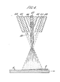
- FIG. 4 illustrates a coating head suitable for use in the practice of the second embodiment of the invention.
- Molten metal 47 is brought under pressure to the molten metal nozzle 46 where it exits as a jet stream.
- the jet stream is charged negatively from a high current DC electrical power source (not shown).
- the non-consumable stationary electrode 45 is charged positively from the same power source causing an arc 50 to form between it and the molten metal jet stream.
- Low pressure gas 48 ininert or ambient air
- High pressure gas 49 is introduced between the stationary electrode 45 and the outer cap 44 to atomize and propel the molten metal 47 as a layer 2 onto the substrate 4.
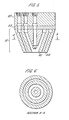
- FIG. 5 illustrates a multiple nozzle apparatus for conveying molten metal 47 and various gases to the nozzle assembly 51 which is connected to plate 52 and plate 53.
- Plate 53 is made of an electrically insulating material such as, for example, aluminum oxide.
- FIG. 6 illustrates a sectional view along line A-A of the multiple nozzle apparatus of FIG. 5.
- FIG. 7 illustrates a plan view of plate 53 (FIG. 5).
- FIG. 8 is a sectional view along line B-B of FIG. 7.
- FIG. 9 shows a sectional view along line CC of FIG. 7.
- Plate 53 contains groups of ports (three per group) which permit the flow of gas 48 and molten metal 47 to the nozzle assembly 51.
- the number of groups of ports is equal to the number of nozzle assemblies required.
- the number of nozzle assemblies required is related to the width of the substrate 4 to be coated.
- FIG. 10 illustrates plan view of plate 52 (FIG. 5).
- FIG. 11 is a sectional view along line D-D of plate 52 (FIG. 10).
- FIG. 12 is a sectional view along line E-E of plate 52 (FIG. 10).
- the function of plate 52 is to manifold the low pressure gas 48, high pressure gas 49 and molten metal 47 to the appropriate ports in plate 53.
- Three inlet connections 56 are provided in plate 52 introducing molten metal 47, low pressure gas 48 and high pressure gas 49.
- Suitable surface preparation includes degreasing in hydrocarbon or in perclorethylene or triclorethylene, followed either by grit blasting, surface abrasion, or a deep chemical etch. For best results, surfaces with re-entrant angular cuts on the surface of the substrate produce the best adhesion of a metallized coating. Thus, grit blasting by angular particles of aluminum oxide, chilled cast iron, or crushed copper slag can be used, being considered superior for this purpose to shot blasting.
- Surface abrasion may be accomplished by the so-called "roto peen” r; process in which carbon particles, embedded in steel, abrade the surface of the metal.
- a deep chemical etch or pickle which etchs into the surface grain structure of the metal may be effected by use of solutions of sulphuric acid or the like.
- the sheet metal after cleaning, is then moved through the coating zone at a speed of up to 300 feet per minute. It will be understood by those skilled in the art that the rate of coverage of the surface area will be a function of the linear speed of the steel substrate past the coating zone and the rete of deposit produced by the molten zinc arc spray.
- the temperature of molten zinc stored in the containers and pumped up to the point of the arc is desirably kept as close as possible to the melting point of zinc, 419.5° C.
- Zinc being expelled from the arc will be in a superheated state, having a temperature of approximately 4000° C. While it is not essential to the practice of the invention, it is also desirable to preheat and/or post heat the steel surface being coated to a temperature of between 200 0 C. and 400° C.
- a useful range of gas pressure delivered to the nozzle is 60 p.s.i. to 150 p.s.i. of air.
- the flow rate of gas from the nozzle at a pressure of 80 p.s.i. should be approximately 25 cubic feet per minute.
- the range of useful spray rates for zinc through the apparatus described is from a few pounds per hour to several hundred pounds per hour.
- the actual spray rate depends, of course, on the thickness desired as well as the linear speed of the steel substrate being coated.
- the range of coating thickness which can be practically achieved is from about 0.001 inches to any desired thickness.
- the distance between the arc point and the surface of the substrate being coated will vary between 1 inch and 10 inches, depending upon the circumstances and variables described above.
Landscapes
- Chemical & Material Sciences (AREA)
- Physics & Mathematics (AREA)
- Engineering & Computer Science (AREA)
- Plasma & Fusion (AREA)
- Chemical Kinetics & Catalysis (AREA)
- Materials Engineering (AREA)
- Mechanical Engineering (AREA)
- Metallurgy (AREA)
- Organic Chemistry (AREA)
- Electromagnetism (AREA)
- Coating By Spraying Or Casting (AREA)
Abstract
Description
- This invention relates to a method and apparatus for coating a corrodible base metal, on one or both sides, with another metal which is molten. More particularly, the invention relates to a method and apparatus for spray metallizing a coating of metal onto one side of the metal, using an electric arc.
- A number of processes are known for the production of sheet steel which is galvanized on one side. These include such conventional methods as the continuous passage of sheet metal through a bath of molten metal, and continuous thermal spraying. Commercial galvanized sheet in which zinc is coated on both sides is not generally acceptable for use in automobile body construction because of complications arising from the adherence of zinc to the tips of welding electrodes in resistance welding processes. Again, while it is desirable to have the zinc covering on interior surfaces where its protective qualities are most needed, it is desirable to leave the exterior surfaces uncoated to promote the adherence of paint or other surface finishes.
- In the case of the thermal spraying process, the material being sprayed, in this case zinc, is supplied to "pot guns" in bulk form and heated to a temperature of approximately 426-482° C., and atomized with a propellant such as air and sprayed onto the surface to be coated. In another version of this process, wire or powder is fed into an oxy-fueled flame which melts it and air atomizes and propels it onto the surface to be coated. Another thermal spray process, electric arc metallizing, which utilizes two metal wires fed to an electric arc, is described in U.S. Patent 3,546,415, herein incorporated by reference.
- These processes all suffer in one way or another from a variety of deficiencies. For instance, the processes which utilize zinc wire or powder are much more expensive than those which use slab zinc, since there is a price differential of over 50% between the two forms of this material. When wire is used, in addition there is a loss due to overspray which can amount to as mcuh as 30 to 40% of the material, leaving a net deposit efficiency of 60 to 65% of material which actually sticks to the metal surface. Galvanizing by hot dipping has several deficiencies. First, the iron-zinc, metallurgical bond, which is formed at the interface between the metals in the form of a crystalline surface, leaves a structure which is brittle and is undesirable for automobile parts, since it cannot be deep drawn; however, other techniques are available to reduce the brittleness of the coating. Another disadvantage of galvanizing is that large open vats are required to accomodate the customary widths of the sheet steel. A great deal of energy is wasted in maintaining the baths at 4260 C. or so, to keep the zinc in the molten state. The disadvantage of "pot gun" process is poor quality of coating and low deposit efficiency.
- It is an object of the present invention to provide a method and apparatus for the continuous spray metallizing of sheet steel with molten zinc, which utilizes slab zinc, is economic in its heat requirements, and in which there is little waste material.
- The above objects and others which will become apparent from the below appended specification are achieved by the present invention in a first embodiment in which the metal which is to form a coating on a substrate is melted in two electrically isolated, heated containers. Molten metal is drawn from each container and conveyed, under pressure, through thermally and electrically insulated pipes, to a coating head. The coating head consists of one or more pairs of nozzles by means of which the two streams of molten zinc are projected and caused to meet at an intersection. The contents of the individual heated containers are connected to either pole of a DC electric power source and electric arc of high intensity is formed where the two jet streams meet superheating the streams of molten metal. The coating metal, in a superheated state, is propelled by a gas onto the surface of the sheet to be coated. It is a distinctive feature of the present invention that, when, for example, slab zinc, the cheapest form of commercially available zinc, is used in conjunction with an electric arc, which has the most economic operation costs, a sprayed zinc coating is produced which is of high quality and, at the same time, is extremely economical.
- A second emodiment of this invention involves melting the metal which is to form a coating on a substrate in an electrically isolated, heated container. Molten metal is drawn from the container and conveyed, under pressure, through a thermally and electrically isolated pipe, to a molten metal nozzle within a coating head where it exits as a jet stream. The jet stream is charged negatively from a high current DC electrical power source. The coating head consists of a stationary electrode which is positively charged from the high current DC electrical power source, which causes an arc to form between it and the negatively charged molten metal jet stream. Low pressure gas is introduced between the molten metal nozzle and the stationary electrode to stabilize the arc. High pressure gas is introduced between the stationary electrode and the outer gap to atomize and propel the molten metal onto the substrate.
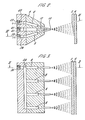
- FIG. 1 is a schematic diagram illustrating an apparatus useful in . carrying out the invention.
- FIG. 2 is a view, in cross section of a coating head embodying the teachings of the first embodiment of the invention, taken along lines II of FIG. 3; and
- FIG. 3 is a side view of the coating head taken along the lines III of FIG. 2.
- FIG. 4 is a schematic diagram of a coating head embodying the teachings of the second embodiment of the invention useful in carrying out the invention.
- FIG. 5 is a view, in cross section, of a coating head embodying the teachings of the second embodiment of the invention.
- FIG. 6 is a sectional view along line A-A (FIG. 5).
- FIG. 7 is a plan view of point 53 (FIG. 5).
- FIG. 8 is a sectional view along line B-B (FIG. 7).
- FIG. 9 is a sectional view along line C-C (FIG. 7).
- FIG. 10 is a plan view of point 52 (FIG. 5).
- FIG. 11 is a sectional view along line D-D (FIG. 10).
- FIG. 12 is a sectional view along line E-E (FIG. 10).
- Reference is now made to FIG. 1, in which a simplified schematic representation of an apparatus for applying a coating of metal to the surface of moving substrate is shown. In the description which follows, as in the drawings, supporting structure which would be conventionally supplied has been omitted in the interest of simplicity of presentation. It will therefore be understood that a
substrate 4, which is being coated, is moved past a zone in front of coating head 6, by means of a conventionalapparatus having rollers 5, in such a way that superheated metallic particles generated by coatinghead 5 are propelled onto the surface ofsubstrate 4 where they unite and congeal to form asolid coating 2. Coating head 6, which is shown in more detail in FIGS. 2 and 3, has a pair ofnozzles 8 which cause two pumped streams of molten metal, such as zinc, aluminum, nickel, stainless steel, or various alloys such as, for example, 85% zinc-15% aluminum or 95% zinc-5% aluminum, to converge at an included angle of approximately 30°. Molten metal traveling in jets to the point ofconvergence 10 is further propelled by a stream of gas, usually air, supplied at high velocity bynozzle 12 which is, conveniently, centrally placed betweennozzles 8 and aimed at point ofconvergence 10. It should be noted that different metals can be simultaneously used in each of the electricallyisolated containers 14. - Molten metal is supplied to each
nozzle 8 fromindividual containers 14. For the sake of illustrative simplicity,containers 14 are simple tanks, shown heated byburners 16, for maintaining slab zinc supplied throughhoppers 20 inmolten pools 18. It will be understood by those skilled in the art that any of a large variety of pots may be used for this purpose, such as a ceramic coated steel pot, a graphite crucible, or any other suitable type of container which can melt slab zinc at a rate appropriate to supply the necessary molten zinc to the moving substrate at a rate appropriate to the desired thickness. - For the sake of simplicity, the illustrative embodiment of FIG. 1 shows
pump 22 for moving the liquid metal fromcontainers 14 tonozzle 8. It will be understood by those skilled in the art that conventional centrifugal liquid metal pumps- 22 for moving the liquid metal fromcontainers 14 tonozzle 8. It will be understood by those skilled in the art that conventional cent- - rifugalliquid metla pumps 22 may be used for this purpose; in the alternative, gravity or pressure feed can also be used. Si-milarly,conduits 24 can be thermally insulated, electrically non-conductive pipe of a conventional nature. ADC power source 26 is connected to the liquid supply system just described byconductors respective container 14, to theliquid metal pool 18 contained therein.DC power source 26 may be either a motor generator, a transformer and rectifier, or simply, DC batteries.Power source 26 should preferably be adjustable to a voltage between 15 and 30 volts, and have electrical response characteristics of the constant voltage type. It should be noted that the instant invention can be practiced with only one container for holding the molten metal to be sprayed, in which case one of thenozzles 8 would be replaced by a non-consumable electrode (e.g., graphite). - FIGS. 2 and 3 illustrate a coating head suitable for use in the practice of the first embodiment of the invention.
Nozzles 8 for liquid metal and air-jet nozzle 12 are formed in a solid, electrically non-conductive, block 9, as by drilling. Materials useful for the body of block 9 are ceramics, for example, such as aluminum oxide, and the like. The channels forming a pair ofnozzles 8 are aimed atconvergence point 10, meeting at an angle of approximately 30°. Air-jet nozzle 12 is also centered on point ofconvergence 10; onesuch nozzle 12 is provided for each pair of liquid-metal-projectingnozzle 8, being centered there between. FIG. 3 illustrates the way in which a series of sets of nozzles is assembleed in the same block to provide coverage across the width of asheet substrate 4. Only onenozzle 8 of a given set can be seen, since the view is from the side. As many sets of liquid-metal-projectingnozzles 8, and air-jet nozzles 12, are used as is required to cover a width of the substrate. As can be seen in FIG. 3, a series ofnozzles 8, on one side of the block, is interconnected by amanifold passage 34 which, in turn, is connected to aninlet 36 through which liquid metal is received from the conduit and distributed to the nozzles. Asimilar connection 38 is provided to alike manifold 39, on the- other side of the coating head, while air is supplied to still another manifold 41, lying in the plane of symmetry of the coating head, through the connectingaperture 40. These connections are shown, in an end view, in FIG. 2. - FIG. 4 illustrates a coating head suitable for use in the practice of the second embodiment of the invention.
Molten metal 47 is brought under pressure to themolten metal nozzle 46 where it exits as a jet stream. The jet stream is charged negatively from a high current DC electrical power source (not shown). The non-consumablestationary electrode 45 is charged positively from the same power source causing anarc 50 to form between it and the molten metal jet stream. Low pressure gas 48 (inert or ambient air) is introduced between themolten metal nozzle 46 and thestationary electrode 45 to stabilize thearc 50.High pressure gas 49 is introduced between thestationary electrode 45 and theouter cap 44 to atomize and propel themolten metal 47 as alayer 2 onto thesubstrate 4. - FIG. 5 illustrates a multiple nozzle apparatus for conveying
molten metal 47 and various gases to thenozzle assembly 51 which is connected to plate 52 andplate 53.Plate 53 is made of an electrically insulating material such as, for example, aluminum oxide. FIG. 6 illustrates a sectional view along line A-A of the multiple nozzle apparatus of FIG. 5. - FIG. 7 illustrates a plan view of plate 53 (FIG. 5). FIG. 8 is a sectional view along line B-B of FIG. 7. FIG. 9 shows a sectional view along line CC of FIG. 7.
Plate 53 contains groups of ports (three per group) which permit the flow ofgas 48 andmolten metal 47 to thenozzle assembly 51. The number of groups of ports is equal to the number of nozzle assemblies required. The number of nozzle assemblies required is related to the width of thesubstrate 4 to be coated. - FIG. 10 illustrates plan view of plate 52 (FIG. 5). FIG. 11 is a sectional view along line D-D of plate 52 (FIG. 10). FIG. 12 is a sectional view along line E-E of plate 52 (FIG. 10). The function of
plate 52 is to manifold thelow pressure gas 48,high pressure gas 49 andmolten metal 47 to the appropriate ports inplate 53. Three inlet connections 56 are provided inplate 52 introducingmolten metal 47,low pressure gas 48 andhigh pressure gas 49. - The process of the invention which, it will be understood can be used to coat a variety of metals on a variety of substrates, will be described in connection with the application of a zinc coating upon a steel substrate.
- Prior to actually moving the substrate through the coating zone, the surface of the metal should be cleaned of all surface contamination such as oil, moisture, dirt, oxides, mill scale, etc. Suitable surface preparation includes degreasing in hydrocarbon or in perclorethylene or triclorethylene, followed either by grit blasting, surface abrasion, or a deep chemical etch. For best results, surfaces with re-entrant angular cuts on the surface of the substrate produce the best adhesion of a metallized coating. Thus, grit blasting by angular particles of aluminum oxide, chilled cast iron, or crushed copper slag can be used, being considered superior for this purpose to shot blasting. Surface abrasion may be accomplished by the so-called "roto peen" r; process in which carbon particles, embedded in steel, abrade the surface of the metal. Again, a deep chemical etch or pickle which etchs into the surface grain structure of the metal may be effected by use of solutions of sulphuric acid or the like.
- The sheet metal, after cleaning, is then moved through the coating zone at a speed of up to 300 feet per minute. It will be understood by those skilled in the art that the rate of coverage of the surface area will be a function of the linear speed of the steel substrate past the coating zone and the rete of deposit produced by the molten zinc arc spray.
- The temperature of molten zinc stored in the containers and pumped up to the point of the arc is desirably kept as close as possible to the melting point of zinc, 419.5° C. Zinc being expelled from the arc will be in a superheated state, having a temperature of approximately 4000° C. While it is not essential to the practice of the invention, it is also desirable to preheat and/or post heat the steel surface being coated to a temperature of between 2000 C. and 400° C.
- A useful range of gas pressure delivered to the nozzle is 60 p.s.i. to 150 p.s.i. of air. The flow rate of gas from the nozzle at a pressure of 80 p.s.i. should be approximately 25 cubic feet per minute.
- The range of useful spray rates for zinc through the apparatus described is from a few pounds per hour to several hundred pounds per hour. The actual spray rate depends, of course, on the thickness desired as well as the linear speed of the steel substrate being coated. The range of coating thickness which can be practically achieved is from about 0.001 inches to any desired thickness. The distance between the arc point and the surface of the substrate being coated will vary between 1 inch and 10 inches, depending upon the circumstances and variables described above.
- It will be understood by those skilled in the art that the molten metal arc spray apparatus and method for coating substrate by means of a molten metal arc spray, described above, will have a variety of applications to a variety of coating metals and substrates. It is therefore intended that the below appended claims be given an interpretation in keeping with the spirit of the invention rather than limited to the specific embodiments described.
Claims (17)
Priority Applications (1)
| Application Number | Priority Date | Filing Date | Title |
|---|---|---|---|
| AT80303076T ATE9767T1 (en) | 1979-09-04 | 1980-09-03 | APPARATUS AND PROCESS FOR COATING A CORROSIVE METAL SUBSTRATE BY SPRAYING A PROTECTIVE METAL. |
Applications Claiming Priority (4)
| Application Number | Priority Date | Filing Date | Title |
|---|---|---|---|
| US72117 | 1979-09-04 | ||
| US06/072,117 US4269867A (en) | 1979-09-04 | 1979-09-04 | Metallizing of a corrodible metal with a protective metal |
| US06/151,839 US4302483A (en) | 1979-09-04 | 1980-05-21 | Metallizing of a corrodible metal with a protective metal |
| US151839 | 1980-05-21 |
Publications (3)
| Publication Number | Publication Date |
|---|---|
| EP0024949A2 true EP0024949A2 (en) | 1981-03-11 |
| EP0024949A3 EP0024949A3 (en) | 1981-04-01 |
| EP0024949B1 EP0024949B1 (en) | 1984-10-10 |
Family
ID=26753017
Family Applications (1)
| Application Number | Title | Priority Date | Filing Date |
|---|---|---|---|
| EP80303076A Expired EP0024949B1 (en) | 1979-09-04 | 1980-09-03 | Apparatus and method for spray metallizing a corrodible metal substrate with a protective metal |
Country Status (7)
| Country | Link |
|---|---|
| US (1) | US4302483A (en) |
| EP (1) | EP0024949B1 (en) |
| AU (1) | AU544427B2 (en) |
| BR (1) | BR8005438A (en) |
| CA (1) | CA1153255A (en) |
| DE (1) | DE3069421D1 (en) |
| MX (1) | MX155450A (en) |
Cited By (3)
| Publication number | Priority date | Publication date | Assignee | Title |
|---|---|---|---|---|
| US5041506A (en) * | 1987-07-10 | 1991-08-20 | Honda Giken Kogyo Kabushiki Kaisha | Method for the production of a molecular composite of rigid aromatic polymer |
| FR2659088A1 (en) * | 1990-03-02 | 1991-09-06 | Gen Electric | PROCESS FOR THE FORMATION OF DISKS CONSISTING OF TWO ALLOYS |
| EP0378673A4 (en) * | 1988-07-19 | 1991-10-23 | United States Department Of Energy | Method and apparatus for atomization and spraying of molten metals |
Families Citing this family (22)
| Publication number | Priority date | Publication date | Assignee | Title |
|---|---|---|---|---|
| US4596189A (en) * | 1984-03-01 | 1986-06-24 | Surface Science Corp. | Lithographic printing plate |
| US4526839A (en) * | 1984-03-01 | 1985-07-02 | Surface Science Corp. | Process for thermally spraying porous metal coatings on substrates |
| CA1285782C (en) * | 1985-12-02 | 1991-07-09 | Peter Buus | Cylindrical freezing drum for slice ice making machines and a method of producing the drum |
| US5401539A (en) * | 1985-11-12 | 1995-03-28 | Osprey Metals Limited | Production of metal spray deposits |
| JPS63176453A (en) * | 1987-01-16 | 1988-07-20 | Dainippon Toryo Co Ltd | Method for producing metal spray coating |
| US4915906A (en) * | 1988-06-17 | 1990-04-10 | Canadian Patents And Development Limited/Societie Canadienne Des Brevets Et D'exploitation Limitee | Novel zinc-based alloys, preparation and use thereof for producing thermal-sprayed coatings having improved corrosion resistance and adherence |
| US5206059A (en) * | 1988-09-20 | 1993-04-27 | Plasma-Technik Ag | Method of forming metal-matrix composites and composite materials |
| US5371937A (en) * | 1990-07-02 | 1994-12-13 | Olin Corporation | Method for producing a composite material |
| US5296667A (en) * | 1990-08-31 | 1994-03-22 | Flame-Spray Industries, Inc. | High velocity electric-arc spray apparatus and method of forming materials |
| US5128172A (en) * | 1990-10-12 | 1992-07-07 | Whittick Thomas E | Continuous coating process with inductive heating |
| EP0505561A4 (en) * | 1990-10-18 | 1994-05-18 | Us Energy | A low temperature process of applying high strength metal coatings to a substrate and article produced thereby |
| US5135166A (en) * | 1991-05-08 | 1992-08-04 | Plasma-Technik Ag | High-velocity thermal spray apparatus |
| GB9316522D0 (en) * | 1993-08-09 | 1993-09-22 | Hopkins William | Apparatus for and methods of producing a particulate spray |
| WO1998018562A1 (en) * | 1996-10-31 | 1998-05-07 | Weirton Steel Corporation | Manufacture of composite-metal slabs and flat-rolled product |
| US6372300B1 (en) | 2000-02-23 | 2002-04-16 | Design Analysis, Inc. | Thermal spray vehicle body manufacturing process |
| US20030228240A1 (en) * | 2002-06-10 | 2003-12-11 | Dwyer James L. | Nozzle for matrix deposition |
| DE102004059008A1 (en) * | 2004-12-08 | 2006-06-14 | Volkswagen Ag | Coating metal components comprises selectively applying a less noble metal than that of the component |
| FI119923B (en) * | 2005-09-08 | 2009-05-15 | Kemppi Oy | Method and apparatus for short arc welding |
| US20090068495A1 (en) * | 2007-09-06 | 2009-03-12 | Dembowski Thaddeus J | Methods and Systems for Re-Metallizing Weld Area in Steel Electrical Conduit |
| SE532457C2 (en) * | 2008-07-03 | 2010-01-26 | Esab Ab | Powder handling device for welding under powder |
| US20130011569A1 (en) * | 2010-12-23 | 2013-01-10 | Jochen Schein | Method and device for arc spraying |
| US8978430B2 (en) * | 2013-03-13 | 2015-03-17 | Commercial Metals Company | System and method for stainless steel cladding of carbon steel pieces |
Family Cites Families (11)
| Publication number | Priority date | Publication date | Assignee | Title |
|---|---|---|---|---|
| US1221104A (en) * | 1913-10-07 | 1917-04-03 | Georg Stolle | Process for making coatings of fusible substances. |
| US1769363A (en) * | 1924-12-22 | 1930-07-01 | Arvidson Nils | Method and means for producing metallic coatings on articles such as type forms and the like |
| GB667485A (en) * | 1949-03-14 | 1952-03-05 | Bo Andren | Metal spraying gun |
| US3016447A (en) * | 1956-12-31 | 1962-01-09 | Union Carbide Corp | Collimated electric arc-powder deposition process |
| US2972185A (en) * | 1958-04-14 | 1961-02-21 | Helen E Brennan | Method of producing strip material |
| US3246114A (en) * | 1959-12-14 | 1966-04-12 | Matvay Leo | Process for plasma flame formation |
| US3179782A (en) * | 1962-02-07 | 1965-04-20 | Matvay Leo | Plasma flame jet spray gun with a controlled arc region |
| US3114826A (en) * | 1962-06-06 | 1963-12-17 | Plasmadyne Corp | High-temperature spray apparatus |
| FR1480209A (en) * | 1965-03-20 | 1967-05-12 | Metrimpex Magyar Mueszeripari | Method and device for moving in particular products having a certain fluidity |
| US3546415A (en) * | 1968-11-07 | 1970-12-08 | Flame Spray Ind Inc | Electric arc metallizing device |
| GB1449162A (en) * | 1973-05-25 | 1976-09-15 | Wellworthy Ltd | Method for reinforcing pistons |
-
1980
- 1980-05-21 US US06/151,839 patent/US4302483A/en not_active Expired - Lifetime
- 1980-08-13 CA CA000358142A patent/CA1153255A/en not_active Expired
- 1980-08-28 BR BR8005438A patent/BR8005438A/en unknown
- 1980-09-02 MX MX183771A patent/MX155450A/en unknown
- 1980-09-03 DE DE8080303076T patent/DE3069421D1/en not_active Expired
- 1980-09-03 EP EP80303076A patent/EP0024949B1/en not_active Expired
- 1980-09-03 AU AU62003/80A patent/AU544427B2/en not_active Ceased
Cited By (3)
| Publication number | Priority date | Publication date | Assignee | Title |
|---|---|---|---|---|
| US5041506A (en) * | 1987-07-10 | 1991-08-20 | Honda Giken Kogyo Kabushiki Kaisha | Method for the production of a molecular composite of rigid aromatic polymer |
| EP0378673A4 (en) * | 1988-07-19 | 1991-10-23 | United States Department Of Energy | Method and apparatus for atomization and spraying of molten metals |
| FR2659088A1 (en) * | 1990-03-02 | 1991-09-06 | Gen Electric | PROCESS FOR THE FORMATION OF DISKS CONSISTING OF TWO ALLOYS |
Also Published As
| Publication number | Publication date |
|---|---|
| US4302483A (en) | 1981-11-24 |
| CA1153255A (en) | 1983-09-06 |
| AU544427B2 (en) | 1985-05-30 |
| MX155450A (en) | 1988-03-11 |
| DE3069421D1 (en) | 1984-11-15 |
| AU6200380A (en) | 1981-03-12 |
| EP0024949B1 (en) | 1984-10-10 |
| BR8005438A (en) | 1981-05-12 |
| EP0024949A3 (en) | 1981-04-01 |
Similar Documents
| Publication | Publication Date | Title |
|---|---|---|
| EP0024949B1 (en) | Apparatus and method for spray metallizing a corrodible metal substrate with a protective metal | |
| US5820938A (en) | Coating parent bore metal of engine blocks | |
| US4269867A (en) | Metallizing of a corrodible metal with a protective metal | |
| US4328257A (en) | System and method for plasma coating | |
| US4232056A (en) | Thermospray method for production of aluminum porous boiling surfaces | |
| GB2195662B (en) | Production of metal spray deposits | |
| EP0172030B1 (en) | Flow coating of metals | |
| JPH11501367A (en) | Apparatus and method for zinc coating steel sheet | |
| US2719820A (en) | Method for coating steel strip | |
| US20060088725A1 (en) | Corrosion-resistant coating for metal substrate | |
| WO2000000318A1 (en) | Methods and apparatus for coating the seams of welded tubes | |
| US4291074A (en) | Process for producing a sheet or strip which is lightly galvanized on one or both sides and products obtained by said process | |
| EP1222050B1 (en) | Method and apparatus for coating the seams of welded tubes | |
| US4595600A (en) | Metal cladding of wire by atomization spraying | |
| CA1050832A (en) | Continuous metal coating process and apparatus | |
| JP2698359B2 (en) | Multi-phase, multi-electrode arc spraying equipment | |
| KR100513773B1 (en) | Method for continuous coating steel sheet and apparatus used therein | |
| RU2094523C1 (en) | Gear for high-speed electric arc wire deposition by spraying | |
| JPH0726362A (en) | Film forming method, film forming plasma torch, and plasma arc oscillating device for the torch | |
| EP4327949A1 (en) | Method and apparatus for coating a galvanized fence panel and the resulting fence panel | |
| Agrawal | Aluminizing of Steel by Gas Atomization Process | |
| Josefsson | Steel Galvanizing | |
| Cunningham | Flame Spraying of Metals | |
| MXPA98010176A (en) | Method to eliminate irregularities in the thermal spraying of the past invert |
Legal Events
| Date | Code | Title | Description |
|---|---|---|---|
| PUAI | Public reference made under article 153(3) epc to a published international application that has entered the european phase |
Free format text: ORIGINAL CODE: 0009012 |
|
| PUAL | Search report despatched |
Free format text: ORIGINAL CODE: 0009013 |
|
| AK | Designated contracting states |
Designated state(s): AT BE CH DE FR GB IT LI LU NL SE |
|
| AK | Designated contracting states |
Designated state(s): AT BE CH DE FR GB IT LI LU NL SE |
|
| 17P | Request for examination filed |
Effective date: 19810720 |
|
| RAP1 | Party data changed (applicant data changed or rights of an application transferred) |
Owner name: MARANTZ, DANIEL RICHARD Owner name: KIDD CREEK MINES LIMITED |
|
| ITF | It: translation for a ep patent filed | ||
| GRAA | (expected) grant |
Free format text: ORIGINAL CODE: 0009210 |
|
| AK | Designated contracting states |
Designated state(s): AT BE CH DE FR GB IT LI LU NL SE |
|
| REF | Corresponds to: |
Ref document number: 9767 Country of ref document: AT Date of ref document: 19841015 Kind code of ref document: T |
|
| REF | Corresponds to: |
Ref document number: 3069421 Country of ref document: DE Date of ref document: 19841115 |
|
| ET | Fr: translation filed | ||
| BECH | Be: change of holder |
Free format text: 841010 *128988 CANADA INC. |
|
| PLBE | No opposition filed within time limit |
Free format text: ORIGINAL CODE: 0009261 |
|
| STAA | Information on the status of an ep patent application or granted ep patent |
Free format text: STATUS: NO OPPOSITION FILED WITHIN TIME LIMIT |
|
| PG25 | Lapsed in a contracting state [announced via postgrant information from national office to epo] |
Ref country code: LU Free format text: LAPSE BECAUSE OF NON-PAYMENT OF DUE FEES Effective date: 19850930 |
|
| 26N | No opposition filed | ||
| PGFP | Annual fee paid to national office [announced via postgrant information from national office to epo] |
Ref country code: AT Payment date: 19860930 Year of fee payment: 7 |
|
| PGFP | Annual fee paid to national office [announced via postgrant information from national office to epo] |
Ref country code: NL Payment date: 19870930 Year of fee payment: 8 |
|
| PG25 | Lapsed in a contracting state [announced via postgrant information from national office to epo] |
Ref country code: GB Effective date: 19890903 Ref country code: AT Effective date: 19890903 |
|
| PG25 | Lapsed in a contracting state [announced via postgrant information from national office to epo] |
Ref country code: SE Effective date: 19890904 |
|
| PG25 | Lapsed in a contracting state [announced via postgrant information from national office to epo] |
Ref country code: LI Effective date: 19890930 Ref country code: CH Effective date: 19890930 Ref country code: BE Effective date: 19890930 |
|
| BERE | Be: lapsed |
Owner name: 128988 CANADA INC. Effective date: 19890930 |
|
| PG25 | Lapsed in a contracting state [announced via postgrant information from national office to epo] |
Ref country code: NL Effective date: 19900401 |
|
| GBPC | Gb: european patent ceased through non-payment of renewal fee | ||
| NLV4 | Nl: lapsed or anulled due to non-payment of the annual fee | ||
| PG25 | Lapsed in a contracting state [announced via postgrant information from national office to epo] |
Ref country code: FR Effective date: 19900531 |
|
| REG | Reference to a national code |
Ref country code: CH Ref legal event code: PL |
|
| PG25 | Lapsed in a contracting state [announced via postgrant information from national office to epo] |
Ref country code: DE Effective date: 19900601 |
|
| REG | Reference to a national code |
Ref country code: FR Ref legal event code: ST |
|
| EUG | Se: european patent has lapsed |
Ref document number: 80303076.6 Effective date: 19900521 |