EP0025813A1 - Appareil pour l'épuration et/ou l'aération d'eau par la flottation à l'air dissous - Google Patents
Appareil pour l'épuration et/ou l'aération d'eau par la flottation à l'air dissous Download PDFInfo
- Publication number
- EP0025813A1 EP0025813A1 EP80100064A EP80100064A EP0025813A1 EP 0025813 A1 EP0025813 A1 EP 0025813A1 EP 80100064 A EP80100064 A EP 80100064A EP 80100064 A EP80100064 A EP 80100064A EP 0025813 A1 EP0025813 A1 EP 0025813A1
- Authority
- EP
- European Patent Office
- Prior art keywords
- jet pump
- water
- pump
- flotation
- outlet
- Prior art date
- Legal status (The legal status is an assumption and is not a legal conclusion. Google has not performed a legal analysis and makes no representation as to the accuracy of the status listed.)
- Granted
Links
Images
Classifications
-
- C—CHEMISTRY; METALLURGY
- C02—TREATMENT OF WATER, WASTE WATER, SEWAGE, OR SLUDGE
- C02F—TREATMENT OF WATER, WASTE WATER, SEWAGE, OR SLUDGE
- C02F3/00—Biological treatment of water, waste water, or sewage
- C02F3/02—Aerobic processes
- C02F3/12—Activated sludge processes
- C02F3/1278—Provisions for mixing or aeration of the mixed liquor
- C02F3/1294—"Venturi" aeration means
-
- C—CHEMISTRY; METALLURGY
- C02—TREATMENT OF WATER, WASTE WATER, SEWAGE, OR SLUDGE
- C02F—TREATMENT OF WATER, WASTE WATER, SEWAGE, OR SLUDGE
- C02F1/00—Treatment of water, waste water, or sewage
- C02F1/24—Treatment of water, waste water, or sewage by flotation
-
- Y—GENERAL TAGGING OF NEW TECHNOLOGICAL DEVELOPMENTS; GENERAL TAGGING OF CROSS-SECTIONAL TECHNOLOGIES SPANNING OVER SEVERAL SECTIONS OF THE IPC; TECHNICAL SUBJECTS COVERED BY FORMER USPC CROSS-REFERENCE ART COLLECTIONS [XRACs] AND DIGESTS
- Y02—TECHNOLOGIES OR APPLICATIONS FOR MITIGATION OR ADAPTATION AGAINST CLIMATE CHANGE
- Y02W—CLIMATE CHANGE MITIGATION TECHNOLOGIES RELATED TO WASTEWATER TREATMENT OR WASTE MANAGEMENT
- Y02W10/00—Technologies for wastewater treatment
- Y02W10/10—Biological treatment of water, waste water, or sewage
Definitions
- the invention relates to a method and a device for water purification and / or aeration by saturating the water with a gas under pressure and then relaxing in a flotation vessel.
- the object of the present invention is therefore to provide improved methods and devices for relaxation flotation, which can be operated more cheaply and, above all, cause lower investment costs by eliminating the autoclave and the compressor.
- the water is no longer saturated with air in a pressure vessel by means of a compressor, but rather the gas-saturated water to be treated is fed to the flotation vessel via two jet pumps connected in series, the first jet pump receiving as a propellant a partial flow of the at least partially treated water and the gas serving the flotation is sucked in via its suction connection, while the second jet pump connected to the outlet of the first jet pump sucks in the water which has not yet been treated via its suction connection in order to supply it to the flotation vessel.
- the invention is characterized in that two jet pumps connected in series with a flotation vessel and a feed pump are provided, that the product water outlet of the flotation vessel is connected via a throttle valve to the propellant inlet of the first jet pump, that the suction Connection of the first jet pump is designed as a gas intake that the output of the first jet pump is connected to the propellant inlet of the second jet pump and that the suction port of the second jet pump is designed as a raw water inlet.
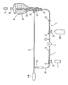
- the flotation panisge shown in the drawing consists of. a first jet pump 1, a second jet pump 2, a flotation tank 3 and a feed pump 4.
- the flotation vessel 3 consists of an upper, partly cylindrical and partly conical section 31, to which a narrower cylindrical section 32 adjoins at the bottom.
- a standpipe 33 protrudes from below into the flotation vessel 3, to which the liquid flow medium to be cleaned, which is loaded with gas bubbles, is fed via the connection 34.
- the connection 34 In the lower part 32 of the Flotation vessel can be removed at 35, the purified water.
- a connection 36 arranged in the upper part of the flotation vessel 3 enables the discharged foreign matter S to be drawn off with a pump.
- the purified product water is measured off via a line 37.
- a branch line 38 and a flow divider or throttle 39 part of the water which has already been treated is fed to the propellant inlet 11 of the first jet pump 1.
- the suction chamber of the jet pump 1 is connected via a connection 13 to the gas required for the flotation, preferably to purified air L. This air dissolves under the pressure built up behind the jet pump 1.
- Propellant inlet 21 of the second suction pump 2 in connection the suction chamber of which receives the raw water RW to be cleaned via the suction connection 23.
- the outlet 22 of this second jet pump 2 is connected to the lower open end 34 of the standpipe 33.
- the pressure drop that occurs in the second jet pump 2 during expansion serves to transport the raw water RW, which is mixed with the finest air bubbles, which can then be separated off in the flotation vessel 3.
- the undissolved constituents entering the standpipe 33 and mixed with air bubbles As already mentioned, the water is drawn off at the upper opening 36 and the purified product water PW at the lower connection 35 of the flotation vessel 3.
- the throughputs are set so that a stationary limit of the air bubbles is established in the flotation vessel 3.
- the feed pump 4 can also be placed in front of the two jet pumps 1, 2. In this case, the feed pump was pumped against a higher dynamic pressure, but on the other hand would not come into contact with air in the pumped medium.
- the advantage of the flotation system according to the invention compared to the previously known relaxation flotation systems is that the noise-prone, noise-producing compressor and the thick-walled pressure vessel are eliminated for safety reasons. It is also advantageous for the arrangement according to the invention that the energy consumption is kept low because the energy used to build up the pressure behind the first jet pump 1 is partially recovered in the second jet pump 2.
- the two jet pumps connected in series result in a particularly effective distribution of gases in liquids, because the water flow supplied during the expansion can be adjusted such that no air bubbles occur more behind the second jet pump, so that. the water is then saturated with air.
- the increased effectiveness of the mass transfer can be attributed to the speed of dissolution between the jet pumps, which is accelerated by increasing the pressure, and the intensive mixing of the water which is oversaturated and under-saturated at normal pressure in the second jet pump.
- the arrangement according to the invention of two series-connected jet pumps is also particularly well suited for the ventilation of sewage treatment plants and fish farming basins, the water flows being able to be set such that a certain proportion of the dissolved air emerges in the form of bubbles for the purpose of removing solids.
- the invention can also be used as a gas scrubber instead of a countercurrent absorption column, which means a considerable reduction in the space requirement.
Landscapes
- Life Sciences & Earth Sciences (AREA)
- Hydrology & Water Resources (AREA)
- Engineering & Computer Science (AREA)
- Environmental & Geological Engineering (AREA)
- Water Supply & Treatment (AREA)
- Chemical & Material Sciences (AREA)
- Organic Chemistry (AREA)
- Biodiversity & Conservation Biology (AREA)
- Microbiology (AREA)
- Physical Water Treatments (AREA)
- Aeration Devices For Treatment Of Activated Polluted Sludge (AREA)
- Gas Separation By Absorption (AREA)
- Separation Of Particles Using Liquids (AREA)
- Cleaning By Liquid Or Steam (AREA)
Priority Applications (1)
| Application Number | Priority Date | Filing Date | Title |
|---|---|---|---|
| AT80100064T ATE1666T1 (de) | 1979-09-21 | 1980-01-07 | Vorrichtung zur wasserreinigung und/oder belssftung durch entspannungsflotation. |
Applications Claiming Priority (2)
| Application Number | Priority Date | Filing Date | Title |
|---|---|---|---|
| DE2938264 | 1979-09-21 | ||
| DE2938264A DE2938264C2 (de) | 1979-09-21 | 1979-09-21 | Vorrichtung zur Wasserreinigung und/oder -belüftung durch Entspannungsflotation |
Publications (2)
| Publication Number | Publication Date |
|---|---|
| EP0025813A1 true EP0025813A1 (fr) | 1981-04-01 |
| EP0025813B1 EP0025813B1 (fr) | 1982-10-20 |
Family
ID=6081494
Family Applications (1)
| Application Number | Title | Priority Date | Filing Date |
|---|---|---|---|
| EP80100064A Expired EP0025813B1 (fr) | 1979-09-21 | 1980-01-07 | Appareil pour l'épuration et/ou l'aération d'eau par la flottation à l'air dissous |
Country Status (9)
| Country | Link |
|---|---|
| EP (1) | EP0025813B1 (fr) |
| JP (1) | JPS5648288A (fr) |
| AT (1) | ATE1666T1 (fr) |
| CS (1) | CS215043B2 (fr) |
| DD (1) | DD149656A5 (fr) |
| DE (1) | DE2938264C2 (fr) |
| DK (1) | DK148901C (fr) |
| HU (1) | HU182096B (fr) |
| PL (1) | PL124739B1 (fr) |
Cited By (1)
| Publication number | Priority date | Publication date | Assignee | Title |
|---|---|---|---|---|
| AU618454B2 (en) * | 1990-02-28 | 1991-12-19 | Syskill (Australia) Pty. Ltd. | Waste water treatment |
Families Citing this family (6)
| Publication number | Priority date | Publication date | Assignee | Title |
|---|---|---|---|---|
| DE8915904U1 (de) * | 1989-01-12 | 1992-02-06 | MRW GmbH Abwasserreinigungssysteme, 8901 Königsbrunn | Vorrichtung zur Abwasserreinigung durch Flockung und Flotation |
| DE4116919A1 (de) * | 1991-05-24 | 1992-11-26 | Henninger Geier Waltraud | Verfahren und vorrichtung zur vorklaerung von schmutzwasser |
| DE4200802C2 (de) * | 1992-01-15 | 1994-12-08 | M U S Mahler Umweltschutz Syst | Vorrichtung zur Reinigung von Abwasser |
| WO1994027918A1 (fr) * | 1993-05-25 | 1994-12-08 | Nauchno-Proizvodstvennaya Firma Bifar | Procede d'epuration des eaux usees, procede de separation de matieres en suspension et procede de saturation d'un liquide par un gaz |
| DE202010009140U1 (de) * | 2010-06-16 | 2010-10-21 | Juan Valdivia Gmbh | Anordnung zur Erzeugung von Luftblasen in Flüssigkeiten |
| AU2018256837A1 (en) * | 2017-04-28 | 2019-12-19 | Nano Gas Technologies, Inc. | Nanogas shear processing |
Citations (4)
| Publication number | Priority date | Publication date | Assignee | Title |
|---|---|---|---|---|
| GB275778A (en) * | 1926-07-16 | 1927-08-18 | Frank Edward Elmore | Improvements in or relating to the separation of materials by flotation |
| DE1230373B (de) * | 1965-11-20 | 1966-12-15 | Beteiligungs & Patentverw Gmbh | Flotationszelle |
| DE1275512B (de) * | 1962-01-08 | 1968-08-22 | Willi Walbersdorf Sondermaschb | Mischvorrichtung |
| US3722679A (en) * | 1970-09-24 | 1973-03-27 | L Logue | Method and means for froth flotation concentration utilizing an aerator having a venturi passage |
Family Cites Families (2)
| Publication number | Priority date | Publication date | Assignee | Title |
|---|---|---|---|---|
| US2446655A (en) * | 1945-10-06 | 1948-08-10 | Deepwater Chemical Co Ltd | Method and apparatus for clarifying alkaline well waters |
| JPS544463A (en) * | 1977-06-13 | 1979-01-13 | Fuso Kensetsu Kogyo | Method of pressurizing* floating and separating sewage |
-
1979
- 1979-09-21 DE DE2938264A patent/DE2938264C2/de not_active Expired
-
1980
- 1980-01-07 AT AT80100064T patent/ATE1666T1/de not_active IP Right Cessation
- 1980-01-07 EP EP80100064A patent/EP0025813B1/fr not_active Expired
- 1980-01-18 JP JP372780A patent/JPS5648288A/ja active Granted
- 1980-01-22 DK DK24780A patent/DK148901C/da not_active IP Right Cessation
- 1980-02-05 HU HU80267A patent/HU182096B/hu unknown
- 1980-02-19 CS CS801156A patent/CS215043B2/cs unknown
- 1980-03-27 DD DD80219970A patent/DD149656A5/de unknown
- 1980-04-17 PL PL1980223540A patent/PL124739B1/pl unknown
Patent Citations (4)
| Publication number | Priority date | Publication date | Assignee | Title |
|---|---|---|---|---|
| GB275778A (en) * | 1926-07-16 | 1927-08-18 | Frank Edward Elmore | Improvements in or relating to the separation of materials by flotation |
| DE1275512B (de) * | 1962-01-08 | 1968-08-22 | Willi Walbersdorf Sondermaschb | Mischvorrichtung |
| DE1230373B (de) * | 1965-11-20 | 1966-12-15 | Beteiligungs & Patentverw Gmbh | Flotationszelle |
| US3722679A (en) * | 1970-09-24 | 1973-03-27 | L Logue | Method and means for froth flotation concentration utilizing an aerator having a venturi passage |
Cited By (1)
| Publication number | Priority date | Publication date | Assignee | Title |
|---|---|---|---|---|
| AU618454B2 (en) * | 1990-02-28 | 1991-12-19 | Syskill (Australia) Pty. Ltd. | Waste water treatment |
Also Published As
| Publication number | Publication date |
|---|---|
| DK24780A (da) | 1981-03-22 |
| DE2938264A1 (de) | 1980-10-30 |
| EP0025813B1 (fr) | 1982-10-20 |
| DK148901C (da) | 1986-04-14 |
| ATE1666T1 (de) | 1982-11-15 |
| JPS5648288A (en) | 1981-05-01 |
| DK148901B (da) | 1985-11-11 |
| CS215043B2 (en) | 1982-06-25 |
| DD149656A5 (de) | 1981-07-22 |
| PL124739B1 (en) | 1983-02-28 |
| HU182096B (en) | 1983-12-28 |
| DE2938264C2 (de) | 1984-10-18 |
| JPH0329475B2 (fr) | 1991-04-24 |
| PL223540A1 (fr) | 1981-05-22 |
Similar Documents
| Publication | Publication Date | Title |
|---|---|---|
| DE69509545T2 (de) | Vorrichtung zur reinigung einer flüssigkeit | |
| EP0208696B1 (fr) | Procede de dissolution de gaz dans un liquide | |
| DE69417374T2 (de) | Membranbioreaktor mit einem Gasliftsystem | |
| DE4341805C1 (de) | Verfahren und Vorrichtung zum biologischen Reinigen von Wasser | |
| EP0029222B1 (fr) | Appareil pour flottation et filtration combinées et procédé de flottation et filtration combinées | |
| DE2818127C2 (de) | Verfahren und Vorrichtung zur Ultrafiltration von Flüssigkeitsgemischen | |
| DE2400653C2 (de) | Verfahren zur Anreicherung einer wäßrigen Flüssigkeit mit Sauerstoff | |
| DE2835709A1 (de) | Verfahren und vorrichtung zum loesen von luft in wasser und anschliessendes entspannen des wassers in flotationsanlagen | |
| DE19719798C1 (de) | Verfahren zum Entfernen von Biomasse aus einer Flüssigkeit mit Hilfe eines Flotationsreaktors | |
| EP0025813B1 (fr) | Appareil pour l'épuration et/ou l'aération d'eau par la flottation à l'air dissous | |
| DE2247240A1 (de) | Flotationsanlage | |
| DE4415637A1 (de) | Verfahren und Vorrichtung zur Klärung und Aufbereitung von Waschwassern aus Fahrzeugwaschanlagen | |
| EP0703828B1 (fr) | Procede et dispositif de separation de substances en suspension dans des fluides | |
| DE2710516A1 (de) | Verfahren und einrichtung zur fluessigkeitsaufbereitung | |
| DE4335104A1 (de) | Verfahren und Vorrichtung zum Filtern von Quellwasser | |
| DE3031755C2 (de) | Verfahren und Vorrichtung zur kontinuierlichen chemischen Behandlung von gelöste, emulgierte und/oder kolloidale Stoffe enthaltenden Flüssigkeiten und zur Abtrennung dieser Stoffe mit Hilfe der Schwerkraft | |
| AT407244B (de) | Verfahren zur biologischen reinigung von abwässern sowie vorrichtung zur durchführung des verfahrens | |
| DE69213433T2 (de) | Vorrichtung zum reinigen schwimmstoffhaltiger industrieller abwässer | |
| DE7209920U (de) | Flotationseinrichtung | |
| DE2117931C3 (de) | Verfahren und Vorrichtung zum Trennen von in einer Flüssigkeit vorhandenen Teilchen unterschiedlicher Größe | |
| DE3717947C2 (fr) | ||
| DE2543296C2 (de) | Membrantrennverfahren und Vorrichtung zu seiner Durchführung | |
| DE188137C (fr) | ||
| DE102005045170A1 (de) | Verfahren und Vorrichtung zur biologischen Abwasserreinigung im Belebungsverfahren | |
| DE2852543A1 (de) | Verfahren zur begasung von fluessigkeiten, insbesondere zum sauerstoffeintrag im belebungsbecken und vorrichtung zur durchfuehrung des verfahrens |
Legal Events
| Date | Code | Title | Description |
|---|---|---|---|
| PUAI | Public reference made under article 153(3) epc to a published international application that has entered the european phase |
Free format text: ORIGINAL CODE: 0009012 |
|
| 17P | Request for examination filed |
Effective date: 19800912 |
|
| AK | Designated contracting states |
Designated state(s): AT BE CH FR GB IT LU NL SE |
|
| ITF | It: translation for a ep patent filed | ||
| GRAA | (expected) grant |
Free format text: ORIGINAL CODE: 0009210 |
|
| AK | Designated contracting states |
Designated state(s): AT BE CH FR GB IT LU NL SE |
|
| REF | Corresponds to: |
Ref document number: 1666 Country of ref document: AT Date of ref document: 19821115 Kind code of ref document: T |
|
| ET | Fr: translation filed | ||
| ITTA | It: last paid annual fee | ||
| PGFP | Annual fee paid to national office [announced via postgrant information from national office to epo] |
Ref country code: LU Payment date: 19920228 Year of fee payment: 13 |
|
| EPTA | Lu: last paid annual fee | ||
| PG25 | Lapsed in a contracting state [announced via postgrant information from national office to epo] |
Ref country code: LU Free format text: LAPSE BECAUSE OF NON-PAYMENT OF DUE FEES Effective date: 19930107 |
|
| PGFP | Annual fee paid to national office [announced via postgrant information from national office to epo] |
Ref country code: SE Payment date: 19931229 Year of fee payment: 15 |
|
| PGFP | Annual fee paid to national office [announced via postgrant information from national office to epo] |
Ref country code: CH Payment date: 19931230 Year of fee payment: 15 Ref country code: GB Payment date: 19931230 Year of fee payment: 15 Ref country code: FR Payment date: 19931230 Year of fee payment: 15 |
|
| PGFP | Annual fee paid to national office [announced via postgrant information from national office to epo] |
Ref country code: BE Payment date: 19940114 Year of fee payment: 15 |
|
| PGFP | Annual fee paid to national office [announced via postgrant information from national office to epo] |
Ref country code: AT Payment date: 19940121 Year of fee payment: 15 |
|
| PGFP | Annual fee paid to national office [announced via postgrant information from national office to epo] |
Ref country code: NL Payment date: 19940131 Year of fee payment: 15 |
|
| PG25 | Lapsed in a contracting state [announced via postgrant information from national office to epo] |
Ref country code: GB Effective date: 19950107 Ref country code: AT Effective date: 19950107 |
|
| PG25 | Lapsed in a contracting state [announced via postgrant information from national office to epo] |
Ref country code: SE Effective date: 19950108 |
|
| EAL | Se: european patent in force in sweden |
Ref document number: 80100064.7 |
|
| PG25 | Lapsed in a contracting state [announced via postgrant information from national office to epo] |
Ref country code: BE Effective date: 19950131 Ref country code: CH Effective date: 19950131 |
|
| BERE | Be: lapsed |
Owner name: GKSS-FORSCHUNGSZENTRUM GEESTHACHT G.M.B.H. Effective date: 19950131 |
|
| PG25 | Lapsed in a contracting state [announced via postgrant information from national office to epo] |
Ref country code: NL Effective date: 19950801 |
|
| GBPC | Gb: european patent ceased through non-payment of renewal fee |
Effective date: 19950107 |
|
| PG25 | Lapsed in a contracting state [announced via postgrant information from national office to epo] |
Ref country code: FR Effective date: 19950929 |
|
| REG | Reference to a national code |
Ref country code: CH Ref legal event code: PL |
|
| NLV4 | Nl: lapsed or anulled due to non-payment of the annual fee |
Effective date: 19950801 |
|
| EUG | Se: european patent has lapsed |
Ref document number: 80100064.7 |
|
| REG | Reference to a national code |
Ref country code: FR Ref legal event code: ST |
|
| PLBE | No opposition filed within time limit |
Free format text: ORIGINAL CODE: 0009261 |
|
| STAA | Information on the status of an ep patent application or granted ep patent |
Free format text: STATUS: NO OPPOSITION FILED WITHIN TIME LIMIT |