EP0027760A1 - Climatiseur par évaporation d'eau pour cabine d'engin - Google Patents
Climatiseur par évaporation d'eau pour cabine d'engin Download PDFInfo
- Publication number
- EP0027760A1 EP0027760A1 EP80401444A EP80401444A EP0027760A1 EP 0027760 A1 EP0027760 A1 EP 0027760A1 EP 80401444 A EP80401444 A EP 80401444A EP 80401444 A EP80401444 A EP 80401444A EP 0027760 A1 EP0027760 A1 EP 0027760A1
- Authority
- EP
- European Patent Office
- Prior art keywords
- air
- air conditioner
- conditioner according
- water
- envelope
- Prior art date
- Legal status (The legal status is an assumption and is not a legal conclusion. Google has not performed a legal analysis and makes no representation as to the accuracy of the status listed.)
- Granted
Links
Images


Classifications
-
- F—MECHANICAL ENGINEERING; LIGHTING; HEATING; WEAPONS; BLASTING
- F24—HEATING; RANGES; VENTILATING
- F24F—AIR-CONDITIONING; AIR-HUMIDIFICATION; VENTILATION; USE OF AIR CURRENTS FOR SCREENING
- F24F6/00—Air-humidification, e.g. cooling by humidification
- F24F6/12—Air-humidification, e.g. cooling by humidification by forming water dispersions in the air
- F24F6/14—Air-humidification, e.g. cooling by humidification by forming water dispersions in the air using nozzles
-
- B—PERFORMING OPERATIONS; TRANSPORTING
- B60—VEHICLES IN GENERAL
- B60H—ARRANGEMENTS OF HEATING, COOLING, VENTILATING OR OTHER AIR-TREATING DEVICES SPECIALLY ADAPTED FOR PASSENGER OR GOODS SPACES OF VEHICLES
- B60H1/00—Heating, cooling or ventilating devices
- B60H1/32—Cooling devices
- B60H1/3202—Cooling devices using evaporation, i.e. not including a compressor, e.g. involving fuel or water evaporation
-
- Y—GENERAL TAGGING OF NEW TECHNOLOGICAL DEVELOPMENTS; GENERAL TAGGING OF CROSS-SECTIONAL TECHNOLOGIES SPANNING OVER SEVERAL SECTIONS OF THE IPC; TECHNICAL SUBJECTS COVERED BY FORMER USPC CROSS-REFERENCE ART COLLECTIONS [XRACs] AND DIGESTS
- Y02—TECHNOLOGIES OR APPLICATIONS FOR MITIGATION OR ADAPTATION AGAINST CLIMATE CHANGE
- Y02B—CLIMATE CHANGE MITIGATION TECHNOLOGIES RELATED TO BUILDINGS, e.g. HOUSING, HOUSE APPLIANCES OR RELATED END-USER APPLICATIONS
- Y02B30/00—Energy efficient heating, ventilation or air conditioning [HVAC]
- Y02B30/54—Free-cooling systems
-
- Y—GENERAL TAGGING OF NEW TECHNOLOGICAL DEVELOPMENTS; GENERAL TAGGING OF CROSS-SECTIONAL TECHNOLOGIES SPANNING OVER SEVERAL SECTIONS OF THE IPC; TECHNICAL SUBJECTS COVERED BY FORMER USPC CROSS-REFERENCE ART COLLECTIONS [XRACs] AND DIGESTS
- Y10—TECHNICAL SUBJECTS COVERED BY FORMER USPC
- Y10S—TECHNICAL SUBJECTS COVERED BY FORMER USPC CROSS-REFERENCE ART COLLECTIONS [XRACs] AND DIGESTS
- Y10S261/00—Gas and liquid contact apparatus
- Y10S261/04—Auto humidifiers
-
- Y—GENERAL TAGGING OF NEW TECHNOLOGICAL DEVELOPMENTS; GENERAL TAGGING OF CROSS-SECTIONAL TECHNOLOGIES SPANNING OVER SEVERAL SECTIONS OF THE IPC; TECHNICAL SUBJECTS COVERED BY FORMER USPC CROSS-REFERENCE ART COLLECTIONS [XRACs] AND DIGESTS
- Y10—TECHNICAL SUBJECTS COVERED BY FORMER USPC
- Y10S—TECHNICAL SUBJECTS COVERED BY FORMER USPC CROSS-REFERENCE ART COLLECTIONS [XRACs] AND DIGESTS
- Y10S62/00—Refrigeration
- Y10S62/16—Roof and ceiling located coolers
Definitions
- the present invention relates to air conditioners of the water evaporation type, making it possible to lower the temperature inside the cabins of machines.
- Known devices of this type most often comprise an annular evaporation chamber centered on a vertical axis which carries, on the one hand, an external air suction fan, which thus passes radially through the chamber, and , on the other hand, a rotating disc maintaining a mist of water in this chamber.
- FIG. 1 of the accompanying drawings schematically shows an air conditioner of this type in the position of use on the roof of a cabin.
- An opening cut in the roof 1 of the cabin provides communication between the air conditioner 2 which is installed on the roof, and an air diffusion console 3, suspended in correspondence, inside the cabin.
- the air sucked in from the outside passes successively through a stage of dry filters 4, a humid filter of cylindrical shape 5, and a chamber of annular shape 6 in which a mist of water is maintained, discharges its droplets d water passing through a second wet filter of cylindrical shape 7, and is pulsed inside the cabin where it exits through the console 3.
- the electric motor 8 with double axis output drives, on the one hand a fan 9 which ensures the movement of the air, on the other hand a disk 10 which is used for the centrifugal spraying of the water which it receives by a tube situated above.
- the water supply mainly comprises a water tank and a small circulation pump.
- the water which flows in the wet filters 5 and 7 and which condenses in the bottom of the annular chamber 6, is recovered in a bowl 11; this bowl has a lateral drain for the water return pipe 12, which circulates at the level of the base of the air conditioner 2, on the roof of the cabin, and goes join the tank.
- this arrangement involves a fan of the helical type, which its installation downstream of the humidification zone makes it work in a saturated atmosphere which harms the endurance of the engine.
- this device leads to large devices, the height of which is sometimes prohibitive when the machines must be able to pass under obstacles.
- the object of the present invention is to remedy these drawbacks by means of an air conditioner which not only remains leak-tight despite the large inclinations and strong jolts of the machines, but while using a fan mounted upstream, ensures in the room evaporation an efficient air-water mist exchange.
- the subject of this invention is in fact an air conditioner comprising a casing provided at one end with an air inlet to be treated and at its opposite end with a treated air outlet, an evaporation chamber inside this envelope, means for propelling the air in the envelope and the water supply means, in which the evaporation chamber comprises at least one inlet port of the propelled air, relatively small and calibrated, and near this orifice, means for forming a water mist which meets the accelerated air flow leaving the orifice but is kept apart from the orifice itself by this air flow.
- the speed of the air flow passing through each calibrated orifice is such that it makes it impossible for any passage of fluid against the current through this orifice, whatever the inclination of the assembly.
- the air and the water mist are entrained in a vortex movement ensuring efficient exchange, in the evaporation chamber.
- the propulsion means can be constituted by one or more centrifugal or helical fans and are in any case located upstream of the envelope so that they work in a dry atmosphere.
- a deflector housing separates the air inlet into the envelope of the evaporation chamber and the calibrated orifices are drilled in this housing.
- the envelope forms at its lower part, below the calibrated orifices and the air outlet, a container for collecting condensed water permanently purged by means of a drain.
- the spraying of water into the chamber is obtained by means of nozzles each mounted near a calibrated lateral orifice for the air inlet of the housing.
- the device comprises an envelope formed by a tank 1 and its cover 2.
- a turbo-fan unit 3 fixed to the outer wall of this tank pulses the air to be treated in the tank, at through an opening 5.
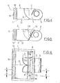
- a deflector box 6, assembled sealingly inside the tank in front of the opening 5 and provided with calibrated lateral orifices 7 and 8, for communication with the tank, forms a distribution box at the inlet of the evaporation chamber formed by the rest of the tank.
- a spray nozzle 9, 10 connected to a conventional water supply, comprising in particular a water tank and a pump (not shown) mounted on the machine.
- the nozzles 9 and 10 are supported by the wall 35 which has the air inlet opening 5 and are directed approximately parallel to the calibrated orifices 7, 8 respectively, so that the water mist coming from each nozzle has a general direction perpendicular to the air stream exiting through the calibrated orifice, as shown by the arrows in FIG. 3.
- the wall 36 of the housing deflector 6 which faces the opening 5 has a curved shape, its concavity being turned towards this opening. It can thus form a portion of generator cylinder parallel to this opening, or, as shown in FIG. 3, also be curved in its middle part in the direction of this opening and form two deflecting elements in opposite directions which guide the air to the two opposite orifices 7 and 8 of the housing.
- the distribution box thus performs a triple function: first, it deflects the air flow received from the fan and straightens it by directing it on each side, meeting the jets of water spray from nozzles 9 and 10; secondly, it seals upstream fog water, which cannot cross the zone of calibrated openings 7 and 8 where the air speed is maximum; thirdly, it reconstitutes the partition of tank 1, preventing the flow of condensed water through the opening 5, even in the event of strong shaking.
- the air-water mixture thus obtained in the tank which constitutes an evaporation chamber, promotes the phenomenon of evaporation until saturation, which is accompanied by the cooling of the treated air.
- the air flow Before escaping from the tank 1 through an opening 11 made in the upper part of the wall 31 of the tank opposite the wall 35, the air flow passes through a droplet separating medium 12.
- This media made of cellular, porous, fibrous or spongy material, permeable to air, covers the entire internal face of the wall 31 and ensures intimate contact with the air and the water which condenses and flows towards the bottom.
- the part of the tank located below the calibrated orifices plays the role of a condensed water recovery tank, but this water collected at the bottom of the tank is permanently purged by a drain 13, and returns to the tank and to the supply pump. .
- the cover 2 of the chamber is in correspondence with the roof 14 of the cabin; the assembly is installed in a console 15.
- the air to be treated is taken through a filter 16, flows laterally between the air conditioner and the console to reach the turbo-fan; it is expelled after treatment, in a guide 17 in the direction of the air vents 18.
- the cover 12 is always in correspondence with the roof 14, but the air conditioner is installed in the reverse position from the previous one.
- the seal is ensured between the air conditioner and the console by a seal 19 to prevent recycling.
- the air conditioner is installed in a vertical position, along the wall of the passenger compartment; the cover 2 can then additionally perform the covering function of the assembly and cover the air conditioner on its front as well as its sides; the water return drain is located at the lowest point 13 of the evaporation chamber in this configuration, the calibrated openings 7, 8 being limited to the upper part of the side wall of the box 6.
- the cover 2 is cased so as to cover the device on its upper and lateral faces and to carry a suction filter 20; the compact assembly thus obtained is installed directly on the roof 14-of the cabin. The treated air is then blown into the passenger compartment through a cutout leading to a console 21 carrying the controls and diffusers 18.
- the cover 2 is cambered as before.
- the body thus obtained is assembled at its periphery, to a console 22 carrying the controls and the nozzles 18.
- a watertight partition 29 prevents the recycling of air.
- the compact monobloc assembly thus obtained forms an air conditioner ready to be installed directly in the opening of roofs which have a ventilation or safety hatch.
- the block can in this case be secured by clamping using a cross member 23 bearing under the edges of the opening, inside the cabin, assembled by the screws 24, to the air conditioner assembly the console 22 of which carries nuts 25.
- the device, object of the invention can be used in all cases where it is sought to lower the ambient temperature of a passenger compartment, or to humidify it or both simultaneously, to improve comfort. These results are obtained without the need for a compressor or a refrigerant circuit. Its design allows it to function properly even with a strong inclination and strong jolts.
- the turbo-fan which can be replaced without drawback by one or more axial fans or the like, not only is mounted upstream of the assembly and works in a dry atmosphere, but can be tightly attached to one end of the envelope, which makes it possible to produce an air conditioner with reduced volume.
- the evaporation chamber is made much more compact, and the reduction in its dimensions associated with the installation of a drain drain with immediate vertical descent prevents the condensed water from staying and therefore from making significant waves.
- the calibrated orifices are located at the upper part of the deflector housing, the limit angle of overflow at rest is very much increased.
- the compactness of the chamber-fan assembly reduces the height of the air conditioner.
- the water mist can be formed by means other than the nozzles, for example by means of one or more rotating discs associated with water inlet conduits.
- the number of calibrated orifices and nozzles, discs or other, as well as their relative positions can vary depending on the application of the air conditioner, whatever they are, the means for forming the water mist are advantageously controlled by the control of the fan so as to prohibit their operation during the latter's shutdown.
- a spongy material with open, communicating cells can be placed at the bottom of the tank in order to stabilize the surface of the water.
Landscapes
- Engineering & Computer Science (AREA)
- Chemical & Material Sciences (AREA)
- Mechanical Engineering (AREA)
- Dispersion Chemistry (AREA)
- Combustion & Propulsion (AREA)
- General Engineering & Computer Science (AREA)
- Physics & Mathematics (AREA)
- Thermal Sciences (AREA)
- Air-Conditioning For Vehicles (AREA)
- Devices For Blowing Cold Air, Devices For Blowing Warm Air, And Means For Preventing Water Condensation In Air Conditioning Units (AREA)
Abstract
Description
- La présente invention concerne les climatiseurs du type par évaporation d'eau, permettant d'abaisser la température à l'intérieur des cabines d'engins.
- Les dispositifs connus de ce genre comportent le plus souvent une chambre d'évaporation annulaire centrée sur un axe vertical qui porte, d'une part, un ventilateur d'aspiration de l'air extérieur, qui, ainsi, traverse radialement la chambre, et, d'autre part, un disque rotatif entretenant un brouillard d'eau dans cette chambre.
- La figure 1 des dessins annexés représente schématiquement un climatiseur de ce type en position d'utilisation sur le toit d'une cabine.
- Une ouverture découpée dans le toit 1_de la cabine, assure la communication entre le climatiseur 2 qui est installé sur le toit, et une console de diffusion d'air 3, suspendue en correspondance, à l'intérieur de la cabine. L'air aspiré à l'extérieur passe successivement à travers un étage de filtres secs 4, un filtre humide de forme cylindrique 5, et une chambre de forme annulaire 6 dans laquelle est entretenu un brouillard d'eau, se décharge de ses gouttelettes d'eau en traversant un deuxième filtre humide de forme cylindrique 7, et est pulsé à l'intérieur de la cabine où il sort par la console 3. Le moteur électrique 8 à double sortie d'axe, entraîne, d'une part un ventilateur 9 qui assure le mouvement de l'air, d'autre part un disque 10 qui sert à la pulvérisation centrifuge de l'eau qu'il reçoit par une tubulure située au-dessus. L'alimentation en eau, non représentée sur le dessin, comporte principalement un réservoir d'eau et une petite pompe de circulation. L'eau qui ruisselle dans les filtres humides 5 et 7 et qui se condense dans le fond de la chambre annulaire 6, est récupérée dans une cuvette 11; cette cuvette comporte un drain latéral pour la canalisation de retour d'eau 12, laquelle circule au niveau de-la base du climatiseur 2, sur le toit de la cabine, et va rejoindre le réservoir.
- Un tel dispositif de drainage perd son étanchéité dès que la cabine atteint une certaine inclinaison limite en fonctionnement statique et même bien avant cette position lorsqu'elle subit des à-coups dus au fonctionnement de l'engin, qui ont pour effet de créer des vagues dans la cuvette : dans ce cas, l'eau déborde de la cuvette, ruisselle sur le toit et dans l'intérieur du climatiseur, et s'écoule dans la console 3. La figure 2 schématise l'angle limite d'inclinaison statique.
- Par ailleurs, cette disposition implique un ventilateur de type hélicoïde, que son implantation en aval de la zone d'humidification fait travailler en ambiance saturée ce qui nuit à l'endurance du moteur. De plus, ce dispositif conduit à des appareils de grandes dimensions, dont la hauteur est parfois prohibitive lorsque les engins doivent pouvoir passer sous des obstacles.
- Il a bien été proposé d'utiliser un ventilateur centrifuge monté à l'entrée du climatiseur, mais une telle réalisation se heurte à la difficulté de l'obtention dans ce cas d'un brouillard d'eau et d'un contact prolongé air-eau, de sorte que l'efficacité du climatiseur est faible.
- La présente invention a pour but de remédier à ces inconvénients grâce à un climatiseur qui, non seulement reste étanche aux fuites malgré les fortes inclinaisons et les forts à-coups des machines, mais tout en utilisant un ventilateur monté en amont, assure dans la chambre d'évaporation un échange efficace air-brouillard d'eau.
- Cette invention a en effet pour objet un climatiseur comportant une enveloppe munie à une extrémité d'une entrée d'air à traiter et à son extrémité opposée d'une sortie d'air traité, une chambre d'évaporation à l'intérieur de cette enveloppe, des moyens pour propulser de l'air dans l'enveloppe et des moyens d'alimentation en eau, dans lequel la chambre d'évaporation comporte au moins un orifice d'entrée de l'air propulsé, relativement petit et calibré, et à proximité de cet orifice, des moyens de formation d'un brouillard d'eau qui rencontre le flux d'air accéléré sortant de l'orifice mais est maintenu écarté de l'orifice lui-même par ce flux d'air.
- Dans un tel climatiseur, la vitesse du flux d'air traversant chaque orifice calibré est telle qu'elle rend impossible tout passage de fluide à contre-courant par cet orifice, quelle que soit l'inclinaison de l'ensemble. Par contre, l'air et le brouillard d'eau sont entraînés en un mouvement tourbillonnaire assurant un échange efficace, dans la chambre d'évaporation.
- Les moyens de propulsion peuvent être constitués par un ou plusieurs ventilateurs centrifugesou hélicoîdes et sont de toutes façons implantés en amont de l'enveloppe de sorte qu'ils travaillent en atmosphère sèche.
- Selon une autre caractéristique de l'invention, un boîtier déflecteur sépare l'entrée d'air dans l'enveloppe de la chambre d'évaporation et les orifices calibrés sont percés dans ce boîtier.
- En outre., l'enveloppe forme à sa partie inférieure, en dessous des orifices calibrés et de la sortie d'air un bac de récupération de l'eau condensée purgé en permanence grâce à un drain.
- Selon un mode de réalisation, la pulvérisation de l'eau dans la chambre est obtenue au moyen de buses montées chacune à proximité d'un orifice latéral calibré d'entrée d'air du boîtier.
- Les figures 3 à 11 des dessins annexés illustrent, à titre d'exemple, un mode de réalisation du dispositif conforme à la présente invention.
- La figure 3 est une vue en perspective d'un climatiseur selon l'invention, dont le couvercle a été enlevé.
- La figure 4 est une vue en coupe suivant la ligne A-A de la figure 6.
- La figure 5 est une vue en coupe suivant la ligne B-B de la figure 6.
- La figure 6 est une vue de dessus du climatiseur dont le couvercle a été retiré, représenté sur la figure 3.
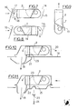
- Les figures 7 et 8 sont des vues schématiques montrant deux variantes de l'installation du climatiseur sur le toit d'une cabine.
- La figure 9 est une vue de côté d'un climatiseur monté en position verticale.
- Les figures 10 et 11 sont des vues schématiques d'autres modes d'installation du climatiseur sur le toit d'une cabine.
- Tel qu'il est représenté sur les dessins, le dispositif comporte une enveloppe formée par un bac 1 et son couvercle 2. Un groupe turbo-ventilateur 3 fixé à la paroi extérieure de ce bac pulse l'air à traiter dans le bac, à travers une ouverture 5. Un boîtier déflecteur 6, assemblé étanchement à l'intérieur du bac devant l'ouverture 5 et muni d'orifices latéraux calibrés 7 et 8, de communication avec le bac, forme une boîte de distribution à l'entrée de la chambre d'évaporation constituée par le reste du bac. De chaque côté de cette boîte est montée une buse de pulvérisation 9, 10, reliée à une alimentation en eau, classique, comprenant notamment un réservoir d'eau et une pompe (non représentés) montés sur l'engin. Les buses 9 et 10 sont supportées par la paroi 35 qui comporte l'ouverture d'entrée d'air 5 et sont dirigées approximativement parallèlement aux orifices calibrés 7, 8 respectivement, de sorte que le brouillard d'eau issu de chaque buse a une direction générale perpendiculaire au filet d'air qui sort par l'orifice calibré, comme le montrent les flèches de la figure 3. De préférence, la paroi 36 du boîtier déflecteur 6 qui fait face à l'ouverture 5, a une forme incurvée, sa concavité étant tournée vers cette ouverture. Elle peut ainsi former une portion de cylindre de génératrice parallèle à cette ouverture, ou, comme représenté sur la figure 3, être également incurvée dans sa partie médiane en direction de cette ouverture et former deux ê- léments déflecteurs en sens inverse qui guident l'air vers les deux orifices opposés 7 et 8 du boîtier. La boîte de distribution assure ainsi une triple fonction : premièrement, elle dévie le flux d'air reçu du ventilateur et le redresse en le dirigeant de chaque côté, à la rencontre des jets d'eau pulvérisée issus des buses 9 et 10; deuxièmement, elle assure l'étanchéité aux remontées de brouillard d'eau vers l'amont, lequel ne peut franchir la zone des ouvertures calibrées 7 et 8 où la vitesse de l'air est maximale; troisièmement, elle reconstitue la cloison du bac 1, empêchant l'écoulement de l'eau condensée, à travers l'ouverture 5, même en cas de fortes secousses. Le mixage air-eau ainsi obtenu dans le bac qui constitue une chambre d'évaporation, favorise le phénomène d'évaporation jusqu'à saturation, qui s'accompagne du rafraîchissement de l'air traité.
- Avant de s'échapper du bac 1 par une ouverture 11 ménagée à la partie supérieure de la paroi 31 du bac opposée à la paroi 35, le flux d'air traverse un média séparateur de gouttelettes 12.
- Ce média en matériau cellulaire, poreux, fibreux, ou spongieux, perméable à l'air, recouvre la totalité de la face interne de la paroi 31 et assure un contact intime de l'air et de l'eau qui se condense et ruisselle vers le bas. La partie du bac située en dessous des orifices calibrés joue le rôle de bac de récupération de l'eau condensée mais cette eau recueillie au fond du bac est purgée en permanence par un drain 13, et retourne au réservoir et à la pompe d'alimentation.
- Selon une application de l'invention, représentée sur la figure 7, le couvercle 2 de la chambre est en correspondance avec le toit 14 de la cabine; l'ensemble est installé dans une console 15. L'air à traiter est prélevé à travers un filtre 16, circule latéralement entre le climatiseur et la console pour atteindre le turbo-ventilateur; il est expulsé après traitement, dans un guide 17 en direction des ouies de diffusion 18.
- Selon une autre variante de l'invention, représentée à la figure 8, le couvercle 12 est toujours en correspondance avec le toit 14, mais le climatiseur est installé en position inverse de la précédente. Dans ce cas, l'étanchéité est assurée entre le climatiseur et la console par un joint étanche 19 pour empêcher le recyclage.
- Selon une autre variante de l'invention, représentée à la figure 9, le climatiseur est installé en position verticale, le long de la paroi de l'habitacle; le couvercle 2 peut alors de surcroît assurer la fonction d'habillage de l'ensemble et carrosser le climatiseur sur sa façade ainsi que ses côtés; le drain de retour d'eau est situé au point le plus bas 13 de la chambre d'évaporation dans cette configuration, les ouvertures calibrées 7, 8 étant limitées à la partie supérieure de la paroi latérale de la boîte 6.
- Selon une autre réalisation de l'invention, représentée sur la figure 10, le couvercle 2 est carrossé de manière à habiller le dispositif sur ses faces supérieure et latérales et à porter un filtre d'aspiration 20; l'ensemble compact ainsi obtenu s'installe directement sur le toit 14-de la cabine. L'air traité est alors pulsé dans l'habitacle à travers une découpe donnant sur une console 21 portant les commandes et les diffuseurs 18. Une cloison étanche 29, située entre la carrosserie et la chambre d'évaporation ou bac, sépare les zones d'aspiration et de refoulement.
- Selon une autre réalisation de l'invention, représentée sur la figure 11, le couvercle 2 est carrossé comme précédemment. La carrosserie ainsi obtenue est assemblée à sa périphérie, à une console 22 portant les commandes et les buses 18. Une cloison étanche 29 empêche le recyclage de l'air. L'ensemble compact monobloc ainsi obtenu forme un climatiseur prêt à être installé directement dans l'ouverture des toits qui possèdent une trappe d'aération ou de sécurité. La fixation du bloc peut dans ce cas être assurée par bridage à l'aide d'une traverse 23 prenant appui sous les bords de l'ouverture, à l'intérieur de la cabine, assemblée par les vis 24, à l'ensemble climatiseur dont la console 22 porte des écrous 25.
- Le dispositif, objet de l'invention, peut être utilisé dans tous les cas où l'on recherche l'abaissement de la température ambiante d'un habitacle, ou son humidification ou les deux simultanément, pour en améliorer le confort. Ces résultats sont obtenus sans nécessiter ni compresseur, ni circuit frigorigène. Sa conception lui permet de fonctionner correctement même avec une forte inclinaison et de fortes secousses.
- En effet, le turbo-ventilateur, qui peut être remplacé sans inconvénient par un ou plusieurs ventilateurs hélicoïdes ou analogue, non seulement est monté en amont de l'ensemble et travaille en atmosphère sèche, mais peut être étroitement accolé à une extrémité de l'enveloppe, ce qui permet de réaliser un climatiseur de volume réduit. La chambre d'évaporation est rendue beaucoup plus compacte, et la diminution de ses dimensions associée à l'implantation d'un drain de purge à descente verticale immédiate empêche l'eau condensée de séjourner et donc de faire des vagues importantes. Comme, en outre, les orifices calibrés sont situés à la partie supérieure du boîtier déflecteur, l'angle limite de débordement au repos est très senblemement accru. Le risque de débordement est encore réduit et même est pratiquement écarté par le fait que les orifices calibrés sont relativement petits et que les flux d'air qui en sortent ont ainsi une vitesse suffisante pour former une barrière anti-retour s'opposant au passage, par ses orifices, du brouillard d'eau ou de l'eau-condensée.
- De plus, la compacité de l'ensemble-chambre - ventilateur permet de réduire la hauteur du climatiseur.
- Bien entendu, le brouillard d'eau peut être formé par des moyens autres que les buses, par exemple au moyen d'un ou de plusieurs disques rotatifs associés à des conduits d'arrivée d'eau. Le nombre des orifices calibrés et des buses, disques ou autres, ainsi que leurs positions relatives pouvant varier en fonction de l'application du climatiseur, quels qu'ils soient, les moyens de formation du brouillard d'eau sont avantageusement asservis à la commande du ventilateur de façon à interdire leur fonctionnement pendant l'arrêt de ce dernier.
- Eventuellement, un matériau spongieux à cellules ouvertes, communicantes, peut être disposé au fond du bac afin de stabiliser la surface de l'eau.
- Des applications particulièrement intéressantes seront obtenues en climatisation pour cabines d'engins agricoles, travaux publics, manutention, mines, chantiers, tout-terrain tels que tracteurs, moissonneuses-batteuses, pelles, chargeurs, engins de piste.
Claims (12)
Applications Claiming Priority (2)
| Application Number | Priority Date | Filing Date | Title |
|---|---|---|---|
| FR7926112A FR2467761A1 (fr) | 1979-10-18 | 1979-10-18 | Climatiseur par evaporation d'eau pour cabines d'engins |
| FR7926112 | 1979-10-18 |
Publications (2)
| Publication Number | Publication Date |
|---|---|
| EP0027760A1 true EP0027760A1 (fr) | 1981-04-29 |
| EP0027760B1 EP0027760B1 (fr) | 1984-02-15 |
Family
ID=9230879
Family Applications (1)
| Application Number | Title | Priority Date | Filing Date |
|---|---|---|---|
| EP80401444A Expired EP0027760B1 (fr) | 1979-10-18 | 1980-10-09 | Climatiseur par évaporation d'eau pour cabine d'engin |
Country Status (7)
| Country | Link |
|---|---|
| US (1) | US4360368A (fr) |
| EP (1) | EP0027760B1 (fr) |
| AU (1) | AU542318B2 (fr) |
| CA (1) | CA1142759A (fr) |
| DE (1) | DE3066619D1 (fr) |
| ES (1) | ES496502A0 (fr) |
| FR (1) | FR2467761A1 (fr) |
Cited By (7)
| Publication number | Priority date | Publication date | Assignee | Title |
|---|---|---|---|---|
| US5373703A (en) * | 1990-09-06 | 1994-12-20 | Pal; Arun K. | Kar-kool |
| FR2865967A1 (fr) | 2004-02-09 | 2005-08-12 | Aerel | Systeme de traitement d'air associant climatisation et purification, pour cabine d'engin |
| KR100885128B1 (ko) | 2007-10-04 | 2009-02-23 | 청솔유기농영농조합법인 | 예냉용 보관상자 |
| FR2995827A1 (fr) * | 2012-09-24 | 2014-03-28 | Peugeot Citroen Automobiles Sa | Dispositif de refroidissement d’air |
| CN107859566A (zh) * | 2016-09-21 | 2018-03-30 | 福特环球技术公司 | 用于从机械空气调节系统提取水用于水喷射的系统和方法 |
| WO2020218947A1 (fr) * | 2019-04-26 | 2020-10-29 | Общество с ограниченной ответственностью "Экологические инновации" | Humidificateur d'air |
| US11079125B2 (en) * | 2019-10-03 | 2021-08-03 | Mistamerica Corporation | Overhead fan misting system and method therefor |
Families Citing this family (18)
| Publication number | Priority date | Publication date | Assignee | Title |
|---|---|---|---|---|
| US4851162A (en) * | 1981-08-24 | 1989-07-25 | Sperr Jr Charles J | Evaporative cooler |
| US5112535A (en) * | 1990-09-07 | 1992-05-12 | Roberson Joe E | Vehicle having a cooling system |
| US5613371A (en) * | 1995-04-07 | 1997-03-25 | Nelson; Kim L. | Method and apparatus for misting vehicle occupants |
| US6112538A (en) * | 1997-08-27 | 2000-09-05 | Mist 'n Co, Inc. | Portable air conditioning apparatus and method using evaporative cooling |
| US6182463B1 (en) * | 1998-08-27 | 2001-02-06 | Christopher J. Strussion | Portable evaporative cooling apparatus |
| ES2159486B1 (es) * | 1999-04-12 | 2002-05-01 | Col Ven Sa | Climatizador de aire para cabinas de transportes y metodo para instalarlo sobre un techo inclinado. |
| ES2159485B1 (es) * | 1999-04-12 | 2002-05-01 | Col Ven Sa | Unidad evaporadora para climatizador de aire |
| US6389835B1 (en) | 1999-06-02 | 2002-05-21 | Joel S. Uranga | Misting system for vehicles |
| US6151907A (en) * | 1999-09-29 | 2000-11-28 | Hale; Roger G. | Misting system for vehicle |
| US6422030B1 (en) | 2001-03-27 | 2002-07-23 | General Shelters Of Texas, S.B., Ltd. | Portable evaporative cooler |
| US20060091234A1 (en) * | 2004-11-01 | 2006-05-04 | Wallander James J | Portable misting system |
| US20070271934A1 (en) * | 2005-02-03 | 2007-11-29 | Aerel | Air Treatment System for Conditioning and Purifying the Air of a Vehicle Cabin |
| EP2379949B1 (fr) * | 2009-01-18 | 2020-02-26 | Lux et Libertas B.V. | Dispositif de refroidissement |
| US8403304B2 (en) * | 2009-07-22 | 2013-03-26 | Golf Cart Misters, Inc. | Open air vehicle cooling device and method |
| US9138761B2 (en) * | 2012-11-28 | 2015-09-22 | CoolFactor, LLC | Intermixing assembly evaporative air conditioner system |
| US20160018118A1 (en) * | 2014-07-15 | 2016-01-21 | Sharon Lee Pirozzi | Mist projector for a riding lawnmower |
| CA3089000A1 (fr) * | 2018-01-19 | 2019-07-25 | Dri-Steem Corporation | Humidificateur avec determination automatique d'intervalle de vidange |
| EP3740715B1 (fr) | 2018-01-19 | 2023-12-20 | DRI-Steem Corporation | Humidificateur à condensation alimenté au gaz présentant une émission ultra-faible de nox |
Citations (12)
| Publication number | Priority date | Publication date | Assignee | Title |
|---|---|---|---|---|
| FR851937A (fr) * | 1938-09-30 | 1940-01-18 | Pulvérisateur-diffuseur à disque | |
| US2267456A (en) * | 1939-11-08 | 1941-12-23 | Howard A Glenn | Cooling unit for vehicles |
| US2596324A (en) * | 1949-06-20 | 1952-05-13 | F A Patchett | Air cooler |
| FR1450898A (fr) * | 1965-10-06 | 1966-06-24 | Defensor Ag | Pulvérisateur de liquide |
| DE1265953B (de) * | 1963-07-22 | 1968-04-11 | Ind Companie Kleinewefers Kons | Befeuchtungsvorrichtung fuer Klimaanlagen |
| US3472147A (en) * | 1967-11-24 | 1969-10-14 | G & G Eng Corp | Air processing system for vehicle cab |
| US3834680A (en) * | 1972-06-12 | 1974-09-10 | W Walker | Air conditioning apparatus for a vehicle cab |
| FR2246831A1 (en) * | 1973-10-09 | 1975-05-02 | Evercool Pty Ltd | Air-conditioning unit - has coolant sprayed onto air-permeable component through which air is driven |
| US3978174A (en) * | 1974-04-01 | 1976-08-31 | Great Plains Industries, Inc. | Evaporator cooler apparatus |
| AU495651B2 (en) * | 1975-04-22 | 1977-10-27 | Metropolitan (Perth) Passenger Transport Trust | Evaporating air cooling unit |
| GB1504385A (en) * | 1976-09-09 | 1978-03-22 | Mann & Son Ltd | J air conditioning apparatus |
| FR2420723A1 (fr) * | 1978-03-20 | 1979-10-19 | Lyon Roland | Dispositif etanche de recuperation d'eau pour climatiseur par evaporation |
Family Cites Families (8)
| Publication number | Priority date | Publication date | Assignee | Title |
|---|---|---|---|---|
| US816371A (en) * | 1905-10-18 | 1906-03-27 | Firm Of Franz Schorg Inhaber L Schorg & K Lohner | Air-purifier. |
| US2152251A (en) * | 1935-12-02 | 1939-03-28 | Norman H Gay | Air conditioning apparatus |
| US2493141A (en) * | 1948-04-13 | 1950-01-03 | Gen Motors Corp | Air conditioning apparatus having an evaporative type condenser |
| US2796014A (en) * | 1954-07-06 | 1957-06-18 | Elmer I Montgomery | Damp air auto cooler |
| US2817960A (en) * | 1954-07-13 | 1957-12-31 | Rheem Mfg Co | Heat exchangers |
| US2983212A (en) * | 1957-08-26 | 1961-05-09 | Poole Gregory | Removable air conditioning units for automobiles |
| US3637195A (en) * | 1968-07-05 | 1972-01-25 | Blazer Corp | Cooling tower apparatus |
| US3686833A (en) * | 1970-05-06 | 1972-08-29 | Richard W Rush | Self-cleaning air scrubber |
-
1979
- 1979-10-18 FR FR7926112A patent/FR2467761A1/fr active Granted
-
1980
- 1980-10-09 DE DE8080401444T patent/DE3066619D1/de not_active Expired
- 1980-10-09 EP EP80401444A patent/EP0027760B1/fr not_active Expired
- 1980-10-10 AU AU63166/80A patent/AU542318B2/en not_active Ceased
- 1980-10-15 US US06/197,324 patent/US4360368A/en not_active Expired - Lifetime
- 1980-10-17 CA CA000362664A patent/CA1142759A/fr not_active Expired
- 1980-10-17 ES ES496502A patent/ES496502A0/es active Granted
Patent Citations (12)
| Publication number | Priority date | Publication date | Assignee | Title |
|---|---|---|---|---|
| FR851937A (fr) * | 1938-09-30 | 1940-01-18 | Pulvérisateur-diffuseur à disque | |
| US2267456A (en) * | 1939-11-08 | 1941-12-23 | Howard A Glenn | Cooling unit for vehicles |
| US2596324A (en) * | 1949-06-20 | 1952-05-13 | F A Patchett | Air cooler |
| DE1265953B (de) * | 1963-07-22 | 1968-04-11 | Ind Companie Kleinewefers Kons | Befeuchtungsvorrichtung fuer Klimaanlagen |
| FR1450898A (fr) * | 1965-10-06 | 1966-06-24 | Defensor Ag | Pulvérisateur de liquide |
| US3472147A (en) * | 1967-11-24 | 1969-10-14 | G & G Eng Corp | Air processing system for vehicle cab |
| US3834680A (en) * | 1972-06-12 | 1974-09-10 | W Walker | Air conditioning apparatus for a vehicle cab |
| FR2246831A1 (en) * | 1973-10-09 | 1975-05-02 | Evercool Pty Ltd | Air-conditioning unit - has coolant sprayed onto air-permeable component through which air is driven |
| US3978174A (en) * | 1974-04-01 | 1976-08-31 | Great Plains Industries, Inc. | Evaporator cooler apparatus |
| AU495651B2 (en) * | 1975-04-22 | 1977-10-27 | Metropolitan (Perth) Passenger Transport Trust | Evaporating air cooling unit |
| GB1504385A (en) * | 1976-09-09 | 1978-03-22 | Mann & Son Ltd | J air conditioning apparatus |
| FR2420723A1 (fr) * | 1978-03-20 | 1979-10-19 | Lyon Roland | Dispositif etanche de recuperation d'eau pour climatiseur par evaporation |
Cited By (8)
| Publication number | Priority date | Publication date | Assignee | Title |
|---|---|---|---|---|
| US5373703A (en) * | 1990-09-06 | 1994-12-20 | Pal; Arun K. | Kar-kool |
| FR2865967A1 (fr) | 2004-02-09 | 2005-08-12 | Aerel | Systeme de traitement d'air associant climatisation et purification, pour cabine d'engin |
| WO2005082654A1 (fr) | 2004-02-09 | 2005-09-09 | Aerel | Systeme de traitement d’air associant climatisation et purification, pour cabine d’engin |
| KR100885128B1 (ko) | 2007-10-04 | 2009-02-23 | 청솔유기농영농조합법인 | 예냉용 보관상자 |
| FR2995827A1 (fr) * | 2012-09-24 | 2014-03-28 | Peugeot Citroen Automobiles Sa | Dispositif de refroidissement d’air |
| CN107859566A (zh) * | 2016-09-21 | 2018-03-30 | 福特环球技术公司 | 用于从机械空气调节系统提取水用于水喷射的系统和方法 |
| WO2020218947A1 (fr) * | 2019-04-26 | 2020-10-29 | Общество с ограниченной ответственностью "Экологические инновации" | Humidificateur d'air |
| US11079125B2 (en) * | 2019-10-03 | 2021-08-03 | Mistamerica Corporation | Overhead fan misting system and method therefor |
Also Published As
| Publication number | Publication date |
|---|---|
| EP0027760B1 (fr) | 1984-02-15 |
| FR2467761B1 (fr) | 1984-05-25 |
| ES8201484A1 (es) | 1981-12-16 |
| FR2467761A1 (fr) | 1981-04-30 |
| ES496502A0 (es) | 1981-12-16 |
| CA1142759A (fr) | 1983-03-15 |
| AU6316680A (en) | 1981-04-30 |
| DE3066619D1 (en) | 1984-03-22 |
| AU542318B2 (en) | 1985-02-21 |
| US4360368A (en) | 1982-11-23 |
Similar Documents
| Publication | Publication Date | Title |
|---|---|---|
| EP0027760B1 (fr) | Climatiseur par évaporation d'eau pour cabine d'engin | |
| EP0392418B1 (fr) | Dispositif de ventilation de moteur de traction ferroviaire et d'épuration de l'air de ventilation | |
| CN102089591B (zh) | 加湿装置 | |
| EP3311721B1 (fr) | Aspirateur | |
| KR20180063725A (ko) | 가습청정장치 | |
| US20190091618A1 (en) | Oil separator | |
| FR2623455A1 (fr) | Dispositif de canalisation de l'eau de pluie pour caisson d'auvent de vehicule automobile | |
| CN108443975A (zh) | 一种空气净化器 | |
| EP0078354B1 (fr) | Dispositif d'insonorisation pour moteurs à combustion interne, notamment pour engins de travaux publics ou agricoles, et engins équipés d'un tel dispositif | |
| US20200325807A1 (en) | Oil separator | |
| JP2006028873A (ja) | 建設機械の吸気装置 | |
| FR2606094A1 (fr) | Pompe centrifuge en tant que pompe de circulation pour des installations de chauffage | |
| JPS63151328A (ja) | 空気浄化装置 | |
| JP3805076B2 (ja) | 自動車用空気調和装置のフィルター | |
| JPH0688490B2 (ja) | 車両用ブロワモ−タ装置 | |
| JPH115429A (ja) | 自動車用空気調和装置のフィルター | |
| JP4985589B2 (ja) | 加湿装置 | |
| CA3026753A1 (fr) | Module de ventilation pour une tour d'aero-refrigeration integrant une roue libre d'aspiration d'air exterieur et de refoulement d'air | |
| JP2569263B2 (ja) | 換気扇用ウェザーカバー | |
| KR100986035B1 (ko) | 에어 덕트의 이물질 배출장치 | |
| KR100860399B1 (ko) | 물필터 | |
| EP1729986B1 (fr) | Systeme de traitement d'air associant climatisation et purification pour cabine d'engin | |
| JP2001219871A (ja) | タイヤハウス | |
| FR2499687A3 (fr) | Humidificateur d'air par evaporation a ventilation forcee | |
| JPS60222394A (ja) | 船外機用導風板付空気取入れ装置 |
Legal Events
| Date | Code | Title | Description |
|---|---|---|---|
| PUAI | Public reference made under article 153(3) epc to a published international application that has entered the european phase |
Free format text: ORIGINAL CODE: 0009012 |
|
| AK | Designated contracting states |
Designated state(s): BE DE GB IT NL SE |
|
| 17P | Request for examination filed |
Effective date: 19810723 |
|
| ITF | It: translation for a ep patent filed | ||
| GRAA | (expected) grant |
Free format text: ORIGINAL CODE: 0009210 |
|
| AK | Designated contracting states |
Designated state(s): BE DE GB IT NL SE |
|
| REF | Corresponds to: |
Ref document number: 3066619 Country of ref document: DE Date of ref document: 19840322 |
|
| PLBE | No opposition filed within time limit |
Free format text: ORIGINAL CODE: 0009261 |
|
| STAA | Information on the status of an ep patent application or granted ep patent |
Free format text: STATUS: NO OPPOSITION FILED WITHIN TIME LIMIT |
|
| 26N | No opposition filed | ||
| ITTA | It: last paid annual fee | ||
| EAL | Se: european patent in force in sweden |
Ref document number: 80401444.7 |
|
| PGFP | Annual fee paid to national office [announced via postgrant information from national office to epo] |
Ref country code: GB Payment date: 19971003 Year of fee payment: 18 |
|
| PGFP | Annual fee paid to national office [announced via postgrant information from national office to epo] |
Ref country code: DE Payment date: 19971024 Year of fee payment: 18 |
|
| PGFP | Annual fee paid to national office [announced via postgrant information from national office to epo] |
Ref country code: SE Payment date: 19971027 Year of fee payment: 18 |
|
| PGFP | Annual fee paid to national office [announced via postgrant information from national office to epo] |
Ref country code: NL Payment date: 19971029 Year of fee payment: 18 |
|
| PGFP | Annual fee paid to national office [announced via postgrant information from national office to epo] |
Ref country code: BE Payment date: 19971118 Year of fee payment: 18 |
|
| PG25 | Lapsed in a contracting state [announced via postgrant information from national office to epo] |
Ref country code: GB Free format text: LAPSE BECAUSE OF NON-PAYMENT OF DUE FEES Effective date: 19981009 |
|
| PG25 | Lapsed in a contracting state [announced via postgrant information from national office to epo] |
Ref country code: SE Free format text: LAPSE BECAUSE OF NON-PAYMENT OF DUE FEES Effective date: 19981010 |
|
| PG25 | Lapsed in a contracting state [announced via postgrant information from national office to epo] |
Ref country code: BE Free format text: LAPSE BECAUSE OF NON-PAYMENT OF DUE FEES Effective date: 19981031 |
|
| BERE | Be: lapsed |
Owner name: LYON ROLAND Effective date: 19981031 |
|
| PG25 | Lapsed in a contracting state [announced via postgrant information from national office to epo] |
Ref country code: NL Free format text: LAPSE BECAUSE OF NON-PAYMENT OF DUE FEES Effective date: 19990501 |
|
| GBPC | Gb: european patent ceased through non-payment of renewal fee |
Effective date: 19981009 |
|
| EUG | Se: european patent has lapsed |
Ref document number: 80401444.7 |
|
| NLV4 | Nl: lapsed or anulled due to non-payment of the annual fee |
Effective date: 19990501 |
|
| PG25 | Lapsed in a contracting state [announced via postgrant information from national office to epo] |
Ref country code: DE Free format text: LAPSE BECAUSE OF NON-PAYMENT OF DUE FEES Effective date: 19990803 |