EP0027766A1 - Verfahren zur numerischen Herstellung beweglicher Bilder identischer Ziele zum elektronischen Eindrücken in ein Landschaftsbild - Google Patents
Verfahren zur numerischen Herstellung beweglicher Bilder identischer Ziele zum elektronischen Eindrücken in ein Landschaftsbild Download PDFInfo
- Publication number
- EP0027766A1 EP0027766A1 EP19800401482 EP80401482A EP0027766A1 EP 0027766 A1 EP0027766 A1 EP 0027766A1 EP 19800401482 EP19800401482 EP 19800401482 EP 80401482 A EP80401482 A EP 80401482A EP 0027766 A1 EP0027766 A1 EP 0027766A1
- Authority
- EP
- European Patent Office
- Prior art keywords
- period
- grid
- target
- during
- image
- Prior art date
- Legal status (The legal status is an assumption and is not a legal conclusion. Google has not performed a legal analysis and makes no representation as to the accuracy of the status listed.)
- Granted
Links
Images


Classifications
-
- G—PHYSICS
- G06—COMPUTING OR CALCULATING; COUNTING
- G06T—IMAGE DATA PROCESSING OR GENERATION, IN GENERAL
- G06T15/00—Three-dimensional [3D] image rendering
- G06T15/10—Geometric effects
- G06T15/20—Perspective computation
Definitions
- the invention relates to a system for the digital production of animated images of identical targets for electronic inlay in a landscape image, in particular for training simulators for cannon shooting.
- a landscape image is produced on the screen of a visualization device, and presented to the student-gunner in the scope of the exercise tank, by means of a optical collimation coupling.
- On this image appears a moving target on which, by means of commands simulating the real commands of the tank and in relation to a calculator, the student practices aiming and shooting.
- the target image is embedded in the landscape image according to any known method, for example by means of a television camera oriented on a model.
- the presentation of several targets according to this principle requires as many cameras oriented respectively on as many separate models of targets and becomes expensive with the increase in the number of targets, due to the costs: cameras, variable magnification optics and systems. of control which ensure the animation of the models.
- the system according to the invention is designed for a "platoon" shooting simulator in which must be represented several identical battle tanks but animated by their own movements. If it also allows to include, economically, for example, a dozen identical targets in the landscape image, it can possibly, relatively relatively, include targets of two types without the result is a prohibitive increase in cost.
- the description which follows relates, for the simplification of the explanation, to the representation of identical targets.
- n images of targets embedded in a landscape image are produced, from m images of target models digitized and assimilated to sets of light elements arranged according to a first grid defined by the numbering method. used and limited by a rectangular mock-up image outline and not part of the apparent outline of the target considered; each of the model images corresponding to a particular a model; the target being assumed to be located at a reference distance from the observer and seen by the latter by means of a telescope adjusted with a reference magnification.
- the target images are assimilated to sets of light elements arranged in a second grid identical to the first grid but limited by a contour homothetic to the outline of the model image according to a first homothetic ratio. equal to 1 / k; the quantity k being a function, on the one hand, of the ratio between the effective distance of the simulated target and the reference distance, and on the other hand, of the ratio between the effective magnification of the telescope and the reference magnification.
- the determination of the light intensity of each light element of a target image consists of: superimposing on the first grid belonging to the model image which is associated with the target image considered , a third grid which is homothetic to the first grid (and to the second grid) according to a second homothetic ratio equal to k, and limited by a homothetic contour to the outline of the model image according to the second homothetic ratio; and to equal the light intensity of each element of the second grid, to the sum of the light intensities divided by k 2 , of the elements and of fractions of elements of the first grid delimited by the particular element of the third grid which is the counterpart of the element of the second grid considered, according to the second homothetic report.
- the dimensions of the elements and of the fractions of elements of the first grid delimited by each element of the third grid are calculated as a function of values - rounded of k and of the coordinates of the center of the element of the third grid considered in relation to the element of the first grid in which the center is located, then, after having been divided by k , are recorded in tables which supply them as the images are calculated.
- the calculation of the luminous intensity honest n divided by k 2, of each component or fraction of each element of the first grid comprises, inter alia, a first product made divided between the two dimensions each by k, of the element or fraction of element considered, and a second product made between the first product and the luminance of this element or this fraction of element.
- the calculations of the first product and of the second product are carried out by a specialized cable operator.
- the action which is supposed to take place on the ground (fig. 1) and which, in the simulation, the student-shooter observes by means of a telescope consists for example, in the passage of several targets CI, C2 ... Cn, in this case battle tanks, following predetermined routes I1, 12, ... In.
- the targets move, from points 01, 02 ... On , at speeds, possibly variable, determined by an instructor. They are located at distances dl, d2, ... dn, from point P where the tank of the student-shooter is supposed to be placed.
- the displacements are calculated by calculation means which assimilate the routes to broken lines formed by predetermined joined segments, on each of which the attitude of each target is invariable.
- the role of the system according to the invention consists, during each image scan of the display device, in producing n target images as a function of the progress of the action in the field, from m digitized images of model and (fig. 4) to embed the n target images calculated during the previous scan, in the landscape image and from the start points of inlay D1, D2, ... Dn whose coordinates are determined by the relative positions of targets and shooter.
- a conventional system which includes, for example: a camera CA, an EN digitization unit, a coupler C, a calculator CL, and a disk D, makes it possible to obtain on the disk D, m digitized images of a model M.
- a set of m digital model images are stored in the form of m groups of first digital data in storage means and correspond to m attitudes different from the model, these storage means are, for example, a magnetic computer disc.
- each model image is assimilated to a set of light elements arranged according to a first grid defined by the digitization process and for each of which the luminance Lij is uniform (FIG. 3).
- This set of elements is limited by a contour of the image of a rectangular model, which is not included in the outline of the target in the attitude considered, and includes 1 rows and J columns of light elements along two axes Oi and Oj.
- the size of the model images corresponds to a reference magnification of the telescope and to a reference distance at which the target is assumed to be located.
- the first digital data includes, for each model image: a first word I giving the number of lines, a second word J giving the number of columns (or of elements per line), as well as a list of words representing respectively the value of the luminance of the elements of the first grid considered successively in the order of the rows and the columns.
- the target images are each formed by a set light elements arranged in a second grid identical to the first grid but limited by a homothetic contour to the outline of the model image in a first homothetic ratio equal to 1 / k; the quantity k being a function, on the one hand, of the ratio between the effective distance of the simulated target and the reference distance, and on the other hand, of the ratio between the effective magnification of the telescope and the reference magnification.
- This function can be easily defined from the laws of classical optics.
- the determination of the light intensity of each light element of a target image consists of: superimposing (fig. 5) on the first grid 1 belonging to the model image which is associated with the target image considered, a third grid 3 homothetic to the first grid and to the second grid according to a second homothetic ratio equal to k and limited by a contour (not shown in fig. 5) homothetic to the outline of the model image, according to the second homothetic ratio ; and equal (fig. 6) the light intensity of each element of the second grid, to the sum of the light intensities divided by k 2 , of the elements and fractions of elements of the first grid delimited by the particular element of the third grid which is the counterpart according to the second ratio of homothety of the element considered of the second grid.
- the elements and the fractions of elements of the first grid delimited by an element of the third grid are thereafter, for simplification, designated under the single term of "plots".
- the dimensions of the elements of the first grid are considered to be equal to the unit while the dimensions of the elements of the third grid are therefore equal to k.
- the center Cmn of each element of the third grid is identified in this third grid as being at the intersection of the nth line and the mth column (fig. 5). It is located inside a determined element of the first grid and identified with respect to this element by the x and y coordinates (fig. 6). These x and y coordinates are linked to the X and Y coordinates of the center considered, with respect to the axes 0i and 0j of the first grid, by the two relations: in which: m and n> 1 are incremented; k is determined by the distance from the target and the magnification of the telescope; i and j are the integer parts and x and y are the fractional parts of the calculated values of X and Y.
- the first grid divides the sides of each element of the third grid into segments identifiable by the indices of the elements of the first grid in which these segments are located.
- the number of these segments in a third grid element depends on the value of k. In Figure 6, for example, this value is between 3 and 4.
- the "horizontal" segments, or crosspieces a are designated by the notations: a (i-2), a (i-1 ), ai, a (i + 1), a (i + 2), while the "vertical" segments, or uprights b, are designated by the notations -b (i-2), b (i-1), bi, b (i + 1), b (i + 2).
- the length of the segments which constitute the dimensions of the plots are easily calculated as a function of x, y and k.
- the preceding relations 1 and 2 provide the values of i, j, x and y; x and y being necessarily less than i and j.
- the table in FIG. 7 gives, for example, the lengths of the crosspieces a as a function of x, when 1 ⁇ k ⁇ 2.
- the lengths of segments a and b are calculated, once and for all, for a set of discrete values k ', x', y 'of k, x and y.
- the calculated lengths are divided by k and then recorded in tables which provide them as the images are calculated.
- the notations a and b are used, for simplicity, both to designate the segments themselves, and their lengths divided by k.
- the light intensities of the elements of the second grids are thus determined in relation to the homologous elements of the third grids.
- these intensities are given by the relation: Lij being the luminance of the element of indices i and j of the first grid.
- the plots form in the element of the third grid a matrix with c columns delimiting c crosspieces a per line and with l lines delimiting l amounts b per column.
- the light intensities of the plots are calculated, depending on the positions of these last in the matrix by considering them successively, column by column, and simultaneously inside each column.
- the areas of the plots equal to the products of the dimensions of the uprights by those of the crosspieces, as well as the light intensities of the plots divided by k 2 , are calculated at each image scanning period of the display device, for each target image and for each element of the third grid.
- a specialized wired circuit performs, for each element of the third grid and under conditions which will be described later, first a first product P equal to aj. bi and then a second product equal to P. Lij.
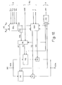
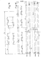
- the general diagram (fig. 8) and the general chronogram (fig. 15) give an overview of the structure and operation of the system according to the invention.
- the storage means MS contain m groups of first digital data representing the light intensities of the elements of m model images.
- the calculation means EC at each image scanning period Tv (fig. 15) of the display device V and during n successive periods Tcl, ... Tcn, carry out the calculations of the light intensities of the elements of n target images and, in addition to data X D , Y Dl ADE, I and J, transfer the n groups of second digital data SDN representing these images, into n storage means EMl, ... EMn.
- EMI storage means ...
- EMn each with two memories MI and M2 mounted "rocker", receive at each scanning period Tv and after the calculation of the nth image, n groups of second digital data and supply a converter digital / analog CDA the n groups of second digital data received during the previous Tv period. This last operation is carried out at the rate of the image scanning of the display device.
- the digital data are received, for example, in the memories Ml during the writing times el, ... in, while the incrustations are carried out by reading the digital data contained in memories 142 during times £ 1, ... ln.
- a conventional GI image generator provides an analog image signal representing the landscape image.
- a conventional overlay system I receives the analog target image signals from the CDA converter as well as the landscape image signal. It transmits all these signals to the visualization V by giving priority to the analog signals of target images.
- a PC control panel allows the instructor responsible for conducting the shooting exercise to display the various parameters relating, for example, to target speeds and the choice of routes.
- a synchronization assembly S distributes the necessary conventional signals to all the circuits mentioned.
- the display device V of the "television monitor" type, supplies the final image formed by the landscape image in which the target images are embedded.
- the general diagram of the calculation means is shown in FIG. 9. They include a central unit UC, a main memory MP, prerecorded tables T and a specialized operator OS. All these means are connected together as well as to the other circuits of the system, by two "bus" connection assemblies, Bl and B2.
- the conventional structure of these links being of no interest for the description of the invention, for the purpose of simplification, the exchange of data and signals are represented in all of the diagrams by equivalent functional links.
- the computing means and more particularly, the central unit and the main memory perform different functions. They determine the values of the calculation parameters relating to each target, namely, inter alia: the coordinates of the target on the ground, its distance d, the route segment on which it is located, the corresponding model image at this segment, the value k, the coordinates X D and Y of the point of beginning of incrustation. They call in the storage means the first digital data corresponding to the selected model image. All these operations take place (fig. 16) during a period Tp located at the start of the period Tc relating to the target considered. They manage the intensity calculations of the target image elements for as many periods Te (Te 11, Te 12, ...
- the data tables T contain and supply the lengths divided by k of the crosspieces a and the amounts b of the plots of the first grid according to the rounded values of k, x and z.
- the specialized wired operator OS performs, at each period T, the 2 calculations of the light intensities divided by k 2 , plots of the first grid delimited by the element of third grid to which the period T considered corresponds. Successive calculations are performed based on the positions of the plots in the matrix of the third grid element.
- the lengths divided by k of the crosspieces a are selected (fig. 17) successively during c periods d2 located at the beginning of c successive periods dl in the period T.
- the lengths divided by k of the uprights b are selected simultaneously (fig. 18) at each of the periods d4 situated at the start of the periods d2.
- the calculation of the light intensity of each plot includes, (fig.
- the diagram of the specialized cable operator is shown in FIG. 10.
- the specialized cable operator comprises: a first register RA comprising as many cells as columns in the matrix, a second register RB comprising as many cells as lines in the matrix, a third RC register comprising as many cells as lines in the matrix, CAI, ... CAl and three-state gates, Pl, ... P £ in number equal to the number of lines.
- the c cells of the first register RA are supplied by the central unit and the main memory at each period d7. They contain the c lengths divided by k, crosspieces a belonging to the plots delimited by the element of the third grid, the intensity of which is being calculated. They supply these lengths, successively, and on a common output S, during the periods d2 included respectively during the c periods dl, and under the action of signals SAl, ... SAc.
- the l cells of the second register RB are supplied by the central unit and the main memory at each period d7 and contain the l lengths divided by k of the amounts b of the plots of the element whose intensity is being calculated.
- Each calculation circuit CA has an input 1 connected exclusively to the output of a cell of the register RB, an input 2 connected to the common output S of the first register RA, an input 4 connected exclusively to a cell of the register RC.
- Each calculation circuit calculates during the c periods d2 included in a period T, the first products and the second products relating to the c plots of this line and of the element relating to the period T considered; the l calculation circuits, simultaneously calculating at each period d2 the first products then the second products relating to the plots of each column of this element.
- the doors P1, ... Pl the inputs of which are each connected to the output of a calculation circuit, are opened successively during the l periods d3 situated at the end of each period dl. Their outputs are connected together and thus route, successively to each period dl, the l second products relating to a column, to the central unit and to the main memory.
- Each calculation circuit comprises a multiplier M, two register cells R1 and R2 and three gates Pa, Pb and Pc with three states.
- a link L is established between the output of the first gate Pa and the output of the third gate Pc.
- the multiplier provides on its output s, the product between the digital data presented to it at its two inputs el and e2. He performs the first product a. b during period d5 and the second product a. b. L during period d6.
- the first gate Pa the input of which constitutes the input 2 of the calculation circuit, is opened by a signal VI (fig. 18) present during the period d4. It provides the data a.
- the second gate Pb has its input connected to a cell of the register Rc. This input constitutes input 4 of the calculation circuit. Its output is connected to the input of the second register. Its opening is controlled by a signal V4 which is only present at each period d2 except during period d4. It provides the value of the luminance L.
- the third gate Pc has its input connected to the output of the multiplier circuit. Its output constitutes output 3 of the calculation circuit. Its opening is controlled by a signal V3 absent only during period d4. It first supplies the first product and then the second product.
- the first cell RI has its input connected, on the one hand, to the output of the first gate Pa and, on the other hand, to the output of the third gate Pc, by the link L.
- the second cell R2 has an input which constitutes the input 1 of the calculation circuit and which is connected to the output of the gate Pb. It registers and supplies to the input c2 of the multiplier and on command of the signal V2, the data b during period d5 then the luminance L during period d6.
- FIG. 12 represents the diagram of a storage unit EM.
- the memories MI and M2 operate "in flip-flop": when one of them receives the second digital data SD4 relating to the next image scanning period Tv from the calculation set (fig. 15), the other provides the digital to analog converter CDA with the second digital data relating to the current scanning period.
- This type of operation is controlled by two signals, in opposition, V and V which determine alternately, at each scanning period, which of the memories is read and which is written.
- the memories also receive signals AI and A2 consisting of the successive addresses of the memory boxes, alternately considered for the reading and writing.
- the memories are constituted by current integrated circuits. Due to the structure of these circuits, the digital data present at their outputs should only be taken into account during the periods when these actually constitute useful data.
- a GAL read address generator provides, in each scanning period, the successive ADL addresses of all the memory boxes. These addresses are formed by a line number NL and by a number NE of elements in the line.
- the addresses AD E for writing the data to the memories are provided by the calculation unit.
- a switching system SC controlled by the signal V, transmits to each of the memories, in the form of the signals AI or A2, and depending on the state of the memory, either the read addresses ADL or the write addresses ADE .
- a memory output validation system VSM supplies the signals V1 and V2.
- a rocker system SB controlled by a signal SV, of period TV, provides the two signals V and V in phase opposition.
- the diagram of the GAL generator is represented in FIG. 13.
- the coordinates Xc and Yc, in the landscape image, of the element scanned, are compared, at each instant, and respectively, to the coordinates X D and Y D of the point at the start of inlay in this landscape image, of the target image corresponding to the storage unit considered.
- a COE comparator supplies a signal 1 when X C > X D.
- a COL comparator supplies a signal 2 when Y C ⁇ Y D.
- Signal 2 resets a CTL counter to zero and allows it to be incremented by a HL clock signal at the rate of line scanning. The capacity of this counter is greater than the largest number of lines provided for a target image.
- the digital content of this counter constitutes, when it is less than I, an NL number which determines a line of the target image to be superimposed.
- an AND circuit provides a signal 3 which resets a CTE counter and allows its incrementation by a clock signal HE at the rate of scanning of the successive elements in a line.
- the capacity of the CTE counter is greater than the number of largest elements expected in a line of the target image.
- the digital content of this counter constitutes, when it is less than J, a NE number which determines a particular element in the line determined by the NL number.
- the signals Xc, Yc, HE and HL come from the synchronization system.
- a comparator CL supplies a signal 1 when the line number NL is greater than the number of lines I in the target image being read.
- a comparator CE supplies a signal 2 when the element number NE is greater than the number of elements J.
- a signal 3 is supplied by an inverter IN when none of the signals 1 and 2 is present at the outputs of the comparators.
- the signals V1 and V2 respectively control the opening of the doors Pl and P2.
- Gate P1 provides signal VI when signal 3 and signal V are present simultaneously while gate P2 provides signal V2 when signal 3 and signal V are present simultaneously.
Landscapes
- Engineering & Computer Science (AREA)
- Theoretical Computer Science (AREA)
- Physics & Mathematics (AREA)
- Computing Systems (AREA)
- Geometry (AREA)
- Computer Graphics (AREA)
- General Physics & Mathematics (AREA)
- Image Processing (AREA)
Applications Claiming Priority (2)
| Application Number | Priority Date | Filing Date | Title |
|---|---|---|---|
| FR7925876A FR2468264A1 (fr) | 1979-10-18 | 1979-10-18 | Systeme de production numerique d'images animees de cibles identiques pour incrustation electronique dans une image de paysage |
| FR7925876 | 1979-10-18 |
Publications (2)
| Publication Number | Publication Date |
|---|---|
| EP0027766A1 true EP0027766A1 (de) | 1981-04-29 |
| EP0027766B1 EP0027766B1 (de) | 1983-09-21 |
Family
ID=9230794
Family Applications (1)
| Application Number | Title | Priority Date | Filing Date |
|---|---|---|---|
| EP19800401482 Expired EP0027766B1 (de) | 1979-10-18 | 1980-10-17 | Verfahren zur numerischen Herstellung beweglicher Bilder identischer Ziele zum elektronischen Eindrücken in ein Landschaftsbild |
Country Status (3)
| Country | Link |
|---|---|
| EP (1) | EP0027766B1 (de) |
| DE (1) | DE3064961D1 (de) |
| FR (1) | FR2468264A1 (de) |
Cited By (4)
| Publication number | Priority date | Publication date | Assignee | Title |
|---|---|---|---|---|
| FR2577097A1 (fr) * | 1985-01-31 | 1986-08-08 | Thomson Csf | Systeme numerique d'incrustation et de masquage de cibles mobiles dans une image de paysage |
| FR2604273A1 (fr) * | 1986-09-20 | 1988-03-25 | Messerschmitt Boelkow Blohm | Procede de generation d'informations de vision pour un systeme de visualisation exterieure pour appareils d'instruction, notamment pour la formation d'equipages de chars |
| EP0439201A3 (en) * | 1986-01-25 | 1993-08-04 | Fujitsu Limited | Consecutive image processing system |
| CN1044159C (zh) * | 1988-09-23 | 1999-07-14 | 汤姆森日用电子产品公司 | 动画图像系列中运动估算的方法和装置 |
Families Citing this family (1)
| Publication number | Priority date | Publication date | Assignee | Title |
|---|---|---|---|---|
| EP0100097B1 (de) * | 1982-07-30 | 1991-01-30 | Honeywell Inc. | Rechnergesteuertes Abbildungssystem |
Citations (2)
| Publication number | Priority date | Publication date | Assignee | Title |
|---|---|---|---|---|
| US3816726A (en) * | 1972-10-16 | 1974-06-11 | Evans & Sutherland Computer Co | Computer graphics clipping system for polygons |
| US4045789A (en) * | 1975-10-29 | 1977-08-30 | Atari, Inc. | Animated video image display system and method |
-
1979
- 1979-10-18 FR FR7925876A patent/FR2468264A1/fr active Granted
-
1980
- 1980-10-17 EP EP19800401482 patent/EP0027766B1/de not_active Expired
- 1980-10-17 DE DE8080401482T patent/DE3064961D1/de not_active Expired
Patent Citations (2)
| Publication number | Priority date | Publication date | Assignee | Title |
|---|---|---|---|---|
| US3816726A (en) * | 1972-10-16 | 1974-06-11 | Evans & Sutherland Computer Co | Computer graphics clipping system for polygons |
| US4045789A (en) * | 1975-10-29 | 1977-08-30 | Atari, Inc. | Animated video image display system and method |
Cited By (4)
| Publication number | Priority date | Publication date | Assignee | Title |
|---|---|---|---|---|
| FR2577097A1 (fr) * | 1985-01-31 | 1986-08-08 | Thomson Csf | Systeme numerique d'incrustation et de masquage de cibles mobiles dans une image de paysage |
| EP0439201A3 (en) * | 1986-01-25 | 1993-08-04 | Fujitsu Limited | Consecutive image processing system |
| FR2604273A1 (fr) * | 1986-09-20 | 1988-03-25 | Messerschmitt Boelkow Blohm | Procede de generation d'informations de vision pour un systeme de visualisation exterieure pour appareils d'instruction, notamment pour la formation d'equipages de chars |
| CN1044159C (zh) * | 1988-09-23 | 1999-07-14 | 汤姆森日用电子产品公司 | 动画图像系列中运动估算的方法和装置 |
Also Published As
| Publication number | Publication date |
|---|---|
| DE3064961D1 (en) | 1983-10-27 |
| FR2468264A1 (fr) | 1981-04-30 |
| FR2468264B1 (de) | 1984-05-04 |
| EP0027766B1 (de) | 1983-09-21 |
Similar Documents
| Publication | Publication Date | Title |
|---|---|---|
| EP0171120B1 (de) | Verfahren und Vorrichtung zur Erzeugung und Veränderung von einem synthetischen Bild | |
| US5949433A (en) | Processing image data | |
| US4965753A (en) | System for constructing images in 3-dimension from digital data to display a changing scene in real time in computer image generators | |
| FR2580840A1 (fr) | Poste d'affichage graphique video et systeme de traitement de donnees graphiques pour poste de travail de conception assistee par ordinateur | |
| FR2493653A1 (fr) | Systeme de restitution de videodisques a vitesse variable | |
| JPS58181172A (ja) | 画像処理装置 | |
| FR2528604A1 (fr) | Procede et appareil pour afficher une image coordonnee sur les ecrans de plusieurs dispositifs d'affichage | |
| FR2566949A1 (fr) | Systeme d'affichage d'images video sur un ecran a balayage ligne par ligne et point par point | |
| IL112940A (en) | Apparatus and method for simulating a terrain and objects thereabove | |
| EP0027766B1 (de) | Verfahren zur numerischen Herstellung beweglicher Bilder identischer Ziele zum elektronischen Eindrücken in ein Landschaftsbild | |
| US5550959A (en) | Technique and system for the real-time generation of perspective images | |
| FR2535871A1 (fr) | Terminal graphique a memoire de points muni d'un systeme d'ecriture en memoire d'image de signaux de texture d'image | |
| DE3323946C2 (de) | Einrichtung zur Erzeugung von Großbildern | |
| DE3035213A1 (de) | Verfahren und vorrichtung zur gewinnung und wiedergabe von gelaendebildern fuer sichtsimulatoren | |
| US4614941A (en) | Raster-scan/calligraphic combined display system for high speed processing of flight simulation data | |
| EP0015839A1 (de) | Verfahren und Systeme zur elektronischen Bilderzeugung in einem grossen Winkelbereich für ein Übungsgerät zur Schiffssteuerung | |
| WO2013016707A1 (en) | Interactive digital content applications | |
| Hristov et al. | A Study on the Digitalization Methods, Visualization Technologies and Interactive Information Systems for Popularization of Tangible and Intangible Heritage | |
| GB2312125A (en) | Virtual studio with zoom control | |
| JPH0241785B2 (de) | ||
| US20070298396A1 (en) | Computer executable dynamic presentation system for simulating human meridian points and method thereof | |
| Hanke et al. | Manufacturing processes of complex shapes and structures using 3D printing and augmented reality | |
| EP0780796B1 (de) | Symbolisches Bildanzeigesystem und -verfahren | |
| Velentzas et al. | SISIFOS: Specialized Illumination SImulator for Orbiting Spacecraft | |
| Tharib | The liminal narrative in temporal reality of sequential art forms: SAFA THARIB |
Legal Events
| Date | Code | Title | Description |
|---|---|---|---|
| PUAI | Public reference made under article 153(3) epc to a published international application that has entered the european phase |
Free format text: ORIGINAL CODE: 0009012 |
|
| AK | Designated contracting states |
Designated state(s): BE DE IT NL |
|
| 17P | Request for examination filed |
Effective date: 19810527 |
|
| GRAA | (expected) grant |
Free format text: ORIGINAL CODE: 0009210 |
|
| ITF | It: translation for a ep patent filed | ||
| AK | Designated contracting states |
Designated state(s): BE DE IT NL |
|
| REF | Corresponds to: |
Ref document number: 3064961 Country of ref document: DE Date of ref document: 19831027 |
|
| PLBE | No opposition filed within time limit |
Free format text: ORIGINAL CODE: 0009261 |
|
| STAA | Information on the status of an ep patent application or granted ep patent |
Free format text: STATUS: NO OPPOSITION FILED WITHIN TIME LIMIT |
|
| 26N | No opposition filed | ||
| PGFP | Annual fee paid to national office [announced via postgrant information from national office to epo] |
Ref country code: DE Payment date: 19930920 Year of fee payment: 14 |
|
| PGFP | Annual fee paid to national office [announced via postgrant information from national office to epo] |
Ref country code: BE Payment date: 19930924 Year of fee payment: 14 |
|
| ITTA | It: last paid annual fee | ||
| PGFP | Annual fee paid to national office [announced via postgrant information from national office to epo] |
Ref country code: NL Payment date: 19931031 Year of fee payment: 14 |
|
| PG25 | Lapsed in a contracting state [announced via postgrant information from national office to epo] |
Ref country code: BE Effective date: 19941031 |
|
| BERE | Be: lapsed |
Owner name: THOMSON-CSF Effective date: 19941031 |
|
| PG25 | Lapsed in a contracting state [announced via postgrant information from national office to epo] |
Ref country code: NL Effective date: 19950501 |
|
| NLV4 | Nl: lapsed or anulled due to non-payment of the annual fee | ||
| PG25 | Lapsed in a contracting state [announced via postgrant information from national office to epo] |
Ref country code: DE Effective date: 19950701 |