EP0028433A1 - Antriebsvorrichtung für ein Gerät, welches eine Schrittschaltung benötigt - Google Patents
Antriebsvorrichtung für ein Gerät, welches eine Schrittschaltung benötigt Download PDFInfo
- Publication number
- EP0028433A1 EP0028433A1 EP80201020A EP80201020A EP0028433A1 EP 0028433 A1 EP0028433 A1 EP 0028433A1 EP 80201020 A EP80201020 A EP 80201020A EP 80201020 A EP80201020 A EP 80201020A EP 0028433 A1 EP0028433 A1 EP 0028433A1
- Authority
- EP
- European Patent Office
- Prior art keywords
- motor
- time
- movable member
- electronic
- shaft
- Prior art date
- Legal status (The legal status is an assumption and is not a legal conclusion. Google has not performed a legal analysis and makes no representation as to the accuracy of the status listed.)
- Granted
Links
Images

Classifications
-
- G—PHYSICS
- G04—HOROLOGY
- G04C—ELECTROMECHANICAL CLOCKS OR WATCHES
- G04C3/00—Electromechanical clocks or watches independent of other time-pieces and in which the movement is maintained by electric means
- G04C3/16—Electromechanical clocks or watches independent of other time-pieces and in which the movement is maintained by electric means incorporating an electro-dynamic continuously rotating motor
-
- H—ELECTRICITY
- H02—GENERATION; CONVERSION OR DISTRIBUTION OF ELECTRIC POWER
- H02P—CONTROL OR REGULATION OF ELECTRIC MOTORS, ELECTRIC GENERATORS OR DYNAMO-ELECTRIC CONVERTERS; CONTROLLING TRANSFORMERS, REACTORS OR CHOKE COILS
- H02P7/00—Arrangements for regulating or controlling the speed or torque of electric DC motors
- H02P7/06—Arrangements for regulating or controlling the speed or torque of electric DC motors for regulating or controlling an individual DC dynamo-electric motor by varying field or armature current
- H02P7/18—Arrangements for regulating or controlling the speed or torque of electric DC motors for regulating or controlling an individual DC dynamo-electric motor by varying field or armature current by master control with auxiliary power
- H02P7/24—Arrangements for regulating or controlling the speed or torque of electric DC motors for regulating or controlling an individual DC dynamo-electric motor by varying field or armature current by master control with auxiliary power using discharge tubes or semiconductor devices
- H02P7/28—Arrangements for regulating or controlling the speed or torque of electric DC motors for regulating or controlling an individual DC dynamo-electric motor by varying field or armature current by master control with auxiliary power using discharge tubes or semiconductor devices using semiconductor devices
- H02P7/285—Arrangements for regulating or controlling the speed or torque of electric DC motors for regulating or controlling an individual DC dynamo-electric motor by varying field or armature current by master control with auxiliary power using discharge tubes or semiconductor devices using semiconductor devices controlling armature supply only
- H02P7/29—Arrangements for regulating or controlling the speed or torque of electric DC motors for regulating or controlling an individual DC dynamo-electric motor by varying field or armature current by master control with auxiliary power using discharge tubes or semiconductor devices using semiconductor devices controlling armature supply only using pulse modulation
- H02P7/291—Arrangements for regulating or controlling the speed or torque of electric DC motors for regulating or controlling an individual DC dynamo-electric motor by varying field or armature current by master control with auxiliary power using discharge tubes or semiconductor devices using semiconductor devices controlling armature supply only using pulse modulation with on-off control between two set points, e.g. controlling by hysteresis
Definitions
- the present invention relates to a drive device for apparatus requiring, for a long period free of maintenance, a safe intermittent drive with a certain mechanical torque.
- Such drive devices are used in particular for recording devices of various parameters, for example technological (mechanical stresses in bridges and engineering structures), economic (flow of pipelines, gas pipelines, etc.), meteorological (pollution of air and water, radiation, sunshine, etc.). Intermittent drives still find many other uses in a wide variety of fields.
- a type of electric motor capable of rendering the desired service, which is characterized by extremely low wear, allowing it to operate, intermittently for several years (up to ten years) without any maintenance service.
- This is the stepper motor.
- the use of a stepping motor in a drive device of the aforementioned type therefore provides a good solution to the second aforementioned problem, encountered in the way of satisfying the imperative in question.
- the stepper motor is not able to provide an adequate solution to the first problem mentioned above, that of great energy saving, that is to say good efficiency.
- the conditions of electrical pulses are fixed and they must be such that sufficient energy is supplied to each step to the motor, taking into account the most severe resistance torque conditions which can be encountered.
- the "on / off" switches of the The DC motor supply was carried out, at least in large part, by electro-mechanical switching members. Mention may be made, in particular, of the device provided for in the single figure of the description DE-AS 23 45 103, device in which a direct current motor is used to provide an intermittent drive and with its main supply current switched on by electronic means, but triggered by electro-mechanical means.
- the object of the present invention is to provide an intermittent training device, of the generic type previously defined, which responds in a completely satisfactory manner to the requirement of very long autonomous life, that is to say that is, it satisfies both the requirement for very good performance and the requirement for very low wear.
- the invention provides a drive device for apparatus requiring, for a long maintenance-free period, an intermittent drive with a certain mechanical torque, characterized in that it comprises: a current motor continuous, an electronic switching circuit capable of establishing and breaking the electrical supply of the DC motor by non-electro-mechanical switching members, latching control means controlling the electronic switching circuit repeatedly, for make it establish said supply, and trigger control means, operating in dependence on a mobile member carried or driven by the output shaft of said motor, and controlling said electronic switching circuit to make it, each time, break said supply as soon as the motor caused said movable member to make a predetermined stroke.
- the DC motor Taking into account its constructive peculiarities and also taking into account the supply voltage (and if necessary the internal resistance of the electric power source) the DC motor will be able to supply a certain maximum torque which, having regard still, if necessary, at a certain kinematic multiplication or reduction, will ensure the mechanical torque necessary in the most unfavorable case for the apparatus to be driven. In any case, less unfavorable. bles, where such a high torque will not be necessary, the DC motor - as this is one of its essential characteristics - will deliver less torque and accelerate further, while limiting the consumption of electrical energy.
- non-electro-mechanical switching elements will be free of twists and will thus limit the wear of the engine as far as possible, which means that we will be able to benefit, as regards the life of the engine without any particular maintenance, of almost all the coefficient "effective walking time / total time". It has been established on the test bench that a device of this kind remains free of prohibitive wear during at least more than five years of operation in intermittent mode, with an effective time of operation approximately equal to 30th of the total time.
- said engagement control means comprise electronic time counting means which periodically deliver engagement pulses to said electronic switching circuit, these time counting means being preferably controlled by a quartz time base.
- these time counting means will advantageously be programmable to deliver said periodic switching pulses at different rates, depending on the type of device driven by the device.
- the said trigger control means comprise a reed contact and at least one magnet disposed on said movable member, so as to act on the reed contact at the end of said predetermined stroke, this reed contact delivering to said electronic switching circuit a trigger pulse each time it passes from the open state to the closed state.
- said predetermined stroke will be a complete revolution of this movable member.
- this movable member is mounted directly on the motor output shaft, the motor will will perform exactly one complete revolution (ignoring any small non-cumulative irregularities) each time the latching control means have caused said electronic switching circuit to establish the supply of the DC motor. If a multiplier or multiplier mechanism is installed between the motor output shaft and said movable member, the motor will perform a fraction of a revolution or more than one revolution each time. Said mechanical torque may be taken from the output shaft of the engine, or from the shaft of said mobile member, or from a mobile intermediate between them. The multiplication or reduction ratio between the motor output shaft and the shaft from which said mechanical torque is taken will, according to an inverse function, a reduction or a multiplication of the mechanical torque obtained compared to the mechanical torque delivered by the engine.
- the reduction or multiplication between the shaft from which said mechanical torque is taken and said movable member will provide a coefficient determining the number of turns or the fraction of a turn that the shaft providing the mechanical torque will perform at each period of motor supply.
- a kinematic chain will exist between the engine output shaft and said movable member, and the construction will be such that the multiplication or reduction ratios will be easily modifiable, so as to establish at will the value of the mechanical torque provided by the device as well as the unit angular stroke of the shaft providing this mechanical torque.
- circuits on the market in the form of integrated circuits, which provide, under the control of a quartz crystal, a predetermined output frequency, preferably 1 Hz.
- these commercial circuits provide one pulse per period. elementary time of a predetermined value (for example 1 ⁇ 2 second, 1 second, 2 seconds, etc.). From disposi Devices of this kind are often supplied with devices which have to take a step at regular time intervals, in particular every minute or every 36 seconds (hundredths of an hour). These existing devices are designed to take a step for example when they have received 60 quantas of elementary angular displacements.
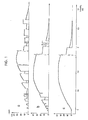
- the other trace corresponds to the case where a diode is connected in anti-parallel to the motor (such as for example the diode D 2 in the diagram of fig. 2); in this case, the inductivity of the motor can maintain a certain current when the contact, connected in series with the parallel mounting of the motor and the diode, is open.
- the diagrams in fig. 1, correspond to the case of a small direct current motor, receiving pulses of the order of 2.5 V and allowing a current of approximately 40 mA to pass on switching on (while it is not yet turning) , current which drops to a much lower value when the motor is in motion.
- the very duration of the pulse is not taken into account (it could be for example between 5 and 20 ms)
- the time scale is indicated for the transient phenomena of establishment of the current and disappearance of the current, and we see that, for example, when the current is switched on using a usual electromechanical contact, rebounds occur during a period which comes to pass 1 ms (with other types of electro-mechanical contacts, this period during which twists occur could even be even longer in particular).
- Fig. 2 shows the diagram of an intermittent drive device in accordance with the proposed design. It is noted that in this case it is a question of supplying, on an output shaft S of the device, mechanical drive pulses repeating at a certain rate, these mechanical pulses having to be supplied with a certain mechanical torque which must being able to reach a certain determined value, corresponding to the most unfavorable driving conditions, and each pulse having to provide a certain angular displacement adapted to the construction and to the operating mode of the device driven by the device.
- the circuits and arrangements provided for operating the motor 11 intermittently include an electronic switching circuit 12, an electronic engagement control circuit 13, and trigger control means 14, comprising a reed contact 17.
- these three circuits or arrangements 12, 13 and 14 are shown framed by a line in lines mixed.
- the electronic circuits 13 and 14 are produced in a form which unites them, an integrated circuit 15, comprising a flip-flop and a programmable divider, forming part for one part of the electronic switching circuit 12 and for the other part of the interlocking control circuit 13.
- a battery or accumulator 21 is connected to two inputs of the interlocking control circuit 13; moreover, a 12 V alternating current supply input is provided between two connection terminals 24, also connected to the interlocking control circuit 13.
- the device shown in FIG. 2 which constitutes a very particular embodiment of the proposed design, can be used in two modes. According to a first mode, which can be applied when an alternating current source is available, the device works mainly by drawing its energy from the alternating current inputs 24, the energy reservoir 21, which is then an accumulator, serving only to provide a power reserve in case the AC power supply fails.
- an accumulator with a capacity of approximately 1.5 Ah can provide sufficient power reserve for more than a month and a half, a duration certainly greater than the longest network outage that one may have to contemplate.
- the second mode of use is suitable if the device is located in a place deprived of any AC power supply.
- the input terminals 24 are not connected and the power source 21 will preferably be a battery or a group of batteries. It is desired to obtain a maintenance-free operating life of several years, typically five years or more. This relatively long duration explains the choice of a battery rather than an accumulator; we do not hardly knows any accumulator, even of a very high performance type, which is capable of conserving the energy with which it is charged for a period exceeding a year.
- very high reliability batteries which have only an insignificant internal leakage current and which are capable of delivering the energy corresponding to most of their initial capacity in the form of a current of the order of 1 mA for at least five years.
- a total discharge current (including the very low internal discharge of the battery) slightly less than 1 mA, it will be possible to reach a completely autonomous operating life of approximately six years.
- Current consumption is established as follows: permanent consumption of electronic circuits, 0.28 mA, integrated motor consumption (average pulse current about 20 mA, pulse ratio about ln65) 0.32 mA, leakage current 0.2 mA internal battery.
- the presently described embodiment proposes the delivery of pulsed pulses, that is to say repeating with a fixed period, but it is quite clear that the proposed design, the main part of which resides in the DC motor. 11, the electronic switching circuit 12, and its control circuits and means (but not necessarily those shown in FIG. 2), would also be suitable for a device giving drive pulses at an arbitrary or random rhythm, depending for example on a meteorological phenomenon.
- the interlocking control circuit 13 is provided with an integrated circuit 16, of a type available on the market.
- This integrated circuit is planned to operate with a quartz Q 1 , at four MHz, and to deliver on its output 3 a frequency of 1 Hz, normally applicable to a stepping motor or to the control stage of a stepping motor.
- Two capacitors CI and C 2 the second variable, allow the frequency to be adjusted.
- the DC voltage supply source (battery constituting the only supply in the second mode of use, power reserve accumulator in the first mode of use) is connected between a common point (connections 7 and 8 of the integrated circuit 16 ) and an input 5 of the integrated circuit 16.
- the alternating voltage, rectified by a diode D 1 , is applied between the same common point and one end of a resistor R 2 whose other end is connected to the input 6 of the integrated circuit.
- a capacitor C 3 filters the rectified voltage.
- the latter is also applied, via a resistor R 1 , to the input point 5 of the integrated circuit, so as to ensure recharging of the accumulator in the case of the first mode of use.
- one could advantageously disconnect the capacitor C 3 ' if it had too great a leakage current; possibly it could be replaced by another capacitor of lower capacity and without leakage current.
- control pulses are obtained, at the output point 3 of the integrated circuit 16, in the interlocking control circuit 13.
- any other method of obtaining control pulses could also be applied to achieve the operation of the device according to the proposed design.
- These pulses in this case at 1 Hz, are applied to the input point A of the integrated circuit 15 which includes the programmable frequency divider. According to presence or absence of a high or low voltage level on three programming inputs B, C and D of this integrated circuit 15, this divider operates with different division cycles and supplies pulses at different frequencies.
- the programmable divider only transmits the second pulses (i.e. works with a division ratio of 1), so that the flip-flop, contained in the same integrated circuit 15, but in the portion thereof which is part of the electronic switching circuit 12, receives a brief pulse every second.
- This flip-flop being of the RS type, this pulse makes it pass to the working state, so that a low level appears on an output F of the integrated circuit 15, which output constitutes an inverted output of the flip-flop.
- An inverter formed by a PNP transistor T 1 and an NPN transistor T 2 is controlled by two resistors R 3 and R 4 , by the output F of the flip-flop 15.
- the transistor T 1 When the latter goes low , the transistor T 1 turns on, while the transistor T 2 is blocked. The positive voltage, coming from the battery, the accumulator or the rectifier (formed by the diode D 1 , the resistor R 2 and the capacitor C 3 ) ' is then brought, by the transistor T 1 to the on state.
- the motor 11 one of the connections of the motor 11, the other connection of which is connected to the negative pole of the power source.
- This motor is activated and actuates a device mul - tiplication or kinematic gear 20, and, at the other end thereof, a movable member 18 carrying a small permanent magnet 19.
- This voltage jump caused the flip to return to the state of rest flop and the passage of the output connection F of the integrated circuit 15 to the high logic level, that is to say at the level of the positive supply voltage.
- the transistor T. comes to the off state, while the transistor T 2 comes to the on state.
- the motor 11 ceases to be supplied by the positive voltage and, moreover, it is short-circuited by the transistor T 2 in the on state.
- a diode D 2 is also mounted in anti-parallel mode on the motor 11 and the emitter-base section of the transistor T 2 , so as to prevent the development of a reverse polarity voltage across the terminals of the motor, when switching off the current. The latter in fact tends to be maintained, due to the inductivity of the motor, with a polarity which is not that for which the transistor T 2 is in the on state.
- the multiplication ratio between the mobile from which the mechanical output torque is taken and the mobile member 18 will make it possible to determine the angular displacement (whole or fractional number of turns) which will be carried out each time by the output shaft of the device.
- the small DC motor 11 can operate without requiring maintenance for a very long period which may extend to at least 5 or 6 years, even 10 years, the ratio of the actual operating time of the motor to total elapsed time being for example of the order of 1/60.
- An intermittent drive of the kind shown in FIG. 2 can advantageously be used for the control of a time indicator (for example with folding panels) or of time marking drums (for example in an obliterating or "stamping" apparatus).
- Existing devices of this type are generally designed to receive mechanical advancement pulses at the rate of one per second, and they include an internal arrangement which causes them to cause the panels to be folded down every minute, or to advance the drum at every minute, or at the end of each 36 second period (hundredth of an hour marking). In this case, it does not matter whether the 60 mechanical pulses are supplied regularly and in isolation or whether they are supplied in one or more blocks. It is here that advantageously comes into play the programmable divider included in the integrated circuit 15.
- the flip-flop 15 will receive a setting pulse in working condition once every 12 seconds.
- the multiplication or reduction ratio will be established between the mobile which supplies the mechanical output torque S and the mobile member 18 so that, for one revolution of the mobile member 18, the output mobile makes a movement angular equal to 12 times that corresponding to a drive step of the device to be controlled.
- the latter instead of receiving 60 mechanical drives, will receive only 5, but 12 times longer, or else, instead of receiving 36 drives, he will receive only 3, but 12 times longer.
- kinematic means connecting the output shaft of the motor 11 to the magnet 19 can be established in different ways.
- the multiplier means Motion multipliers or multipliers can be of different types (gears, chains, etc.) to achieve either a reduction or an amplification of the movement, this being a question of choice and adaptation to the conditions of the device to be driven. It would also be possible to have several magnets 19 at regular angular spacing, on the movable member 18.
- the advantage of grouping the pulses into a single longer mechanical pulse consists of even less wear and tear on the DC motor, as well as an even greater energy saving, since the number of starts and stops is reduced in the proportion of the grouping factor of the pulses.
- the engagement control circuit 13 would be a circuit comprising a calculator for automatically developing an adequate number of pulses, taking into account the position of the panel to be displayed. These pulses could be applied at any suitable speed, regular or irregular, regardless of any question relating to the measurement or the indication of time.
- the elementary period of time may very well be different from one second and even be in an irrational relationship with a period of one second.
- the elementary period of time was one second and the ratio, called M, of "the time interval for the operation of the trained device" to "the elementary period” was 60 or 36.
- the grouping factor (called number N) was 12.
- all the factors of 60, namely 2, 3, 4, 5, 6, 10, 12, 15, 20, 30 may be suitable as group factors N
- a grouping factor of the order of 10 to 15 proves to be adequate with regard to savings in wear and energy consumption.
Landscapes
- Engineering & Computer Science (AREA)
- Power Engineering (AREA)
- Physics & Mathematics (AREA)
- General Physics & Mathematics (AREA)
- Control Of Direct Current Motors (AREA)
- Transmission Devices (AREA)
Applications Claiming Priority (2)
| Application Number | Priority Date | Filing Date | Title |
|---|---|---|---|
| FR7927047A FR2469037A1 (fr) | 1979-10-31 | 1979-10-31 | Dispositif d'entrainement pour appareil necessitant un entrainement intermittent |
| FR7927047 | 1979-10-31 |
Publications (2)
| Publication Number | Publication Date |
|---|---|
| EP0028433A1 true EP0028433A1 (de) | 1981-05-13 |
| EP0028433B1 EP0028433B1 (de) | 1985-08-28 |
Family
ID=9231241
Family Applications (1)
| Application Number | Title | Priority Date | Filing Date |
|---|---|---|---|
| EP80201020A Expired EP0028433B1 (de) | 1979-10-31 | 1980-10-28 | Antriebsvorrichtung für ein Gerät, welches eine Schrittschaltung benötigt |
Country Status (4)
| Country | Link |
|---|---|
| US (1) | US4492905A (de) |
| EP (1) | EP0028433B1 (de) |
| DE (1) | DE3071039D1 (de) |
| FR (1) | FR2469037A1 (de) |
Families Citing this family (2)
| Publication number | Priority date | Publication date | Assignee | Title |
|---|---|---|---|---|
| US20110215748A1 (en) * | 2010-03-05 | 2011-09-08 | Yamatake Corporation | Electric actuator and module for supplying power during a power failure |
| CN113742880B (zh) * | 2020-05-27 | 2024-06-04 | 台达电子工业股份有限公司 | 进给系统的摩擦力预测与补偿方法及电脑可读取存储媒体 |
Citations (4)
| Publication number | Priority date | Publication date | Assignee | Title |
|---|---|---|---|---|
| FR1332784A (fr) * | 1962-06-28 | 1963-07-19 | Procédé pour maintenir constante avec précision la vitesse d'un moteur électrique de faible puissance et dispositif pour sa mise en oeuvre | |
| CH451829A (fr) * | 1965-11-05 | 1968-05-15 | Ebauches Sa | Dispositif de synchronisation d'un moteur à courant continu |
| US3881144A (en) * | 1972-09-08 | 1975-04-29 | Kabushikikaisha Copal | Device for intermittently driving an electromagnetic device |
| US3971204A (en) * | 1974-01-17 | 1976-07-27 | Norio Kawaguchi | Circuit for driving a DC motor for a clock |
Family Cites Families (4)
| Publication number | Priority date | Publication date | Assignee | Title |
|---|---|---|---|---|
| US3617837A (en) * | 1970-10-06 | 1971-11-02 | Honeywell Inc | Pulse actuated motor control circuit |
| GB1450071A (en) * | 1972-10-02 | 1976-09-22 | Citizen Watch Co Lgd | Electronic timepiece |
| JPS5542356B2 (de) * | 1972-12-22 | 1980-10-30 | ||
| US4176517A (en) * | 1974-09-30 | 1979-12-04 | Citizen Watch Co. Ltd. | Integrated circuit for timepiece |
-
1979
- 1979-10-31 FR FR7927047A patent/FR2469037A1/fr active Granted
-
1980
- 1980-10-28 EP EP80201020A patent/EP0028433B1/de not_active Expired
- 1980-10-28 DE DE8080201020T patent/DE3071039D1/de not_active Expired
-
1983
- 1983-03-04 US US06/472,291 patent/US4492905A/en not_active Expired - Lifetime
Patent Citations (4)
| Publication number | Priority date | Publication date | Assignee | Title |
|---|---|---|---|---|
| FR1332784A (fr) * | 1962-06-28 | 1963-07-19 | Procédé pour maintenir constante avec précision la vitesse d'un moteur électrique de faible puissance et dispositif pour sa mise en oeuvre | |
| CH451829A (fr) * | 1965-11-05 | 1968-05-15 | Ebauches Sa | Dispositif de synchronisation d'un moteur à courant continu |
| US3881144A (en) * | 1972-09-08 | 1975-04-29 | Kabushikikaisha Copal | Device for intermittently driving an electromagnetic device |
| US3971204A (en) * | 1974-01-17 | 1976-07-27 | Norio Kawaguchi | Circuit for driving a DC motor for a clock |
Also Published As
| Publication number | Publication date |
|---|---|
| DE3071039D1 (en) | 1985-10-03 |
| FR2469037A1 (fr) | 1981-05-08 |
| EP0028433B1 (de) | 1985-08-28 |
| US4492905A (en) | 1985-01-08 |
| FR2469037B1 (de) | 1983-08-12 |
Similar Documents
| Publication | Publication Date | Title |
|---|---|---|
| EP0239820B1 (de) | Umformer von mechanischer in elektrische Energie | |
| FR2529032A1 (fr) | Procede d'alimentation d'un moteur pas a pas monophase pour piece d'horlogerie | |
| EP3299908B1 (de) | Armbanduhr mit automatischem aufzug | |
| EP0161582B1 (de) | Schrittmotoranordnung | |
| EP0028433B1 (de) | Antriebsvorrichtung für ein Gerät, welches eine Schrittschaltung benötigt | |
| CH690523A5 (fr) | Pièce d'horlogerie comportant une génératrice d'énergie électrique. | |
| EP1230726B1 (de) | Stellantrieb für das klimaanlageventil eines kraftfahrzeugs | |
| EP0013225B1 (de) | Vorrichtung zur Steuerung der hin- und hergehenden Bewegung einer beweglichen Ausrüstung, wie z.B. des Wagens einer elektrostatischen Spritzeinheit durch Verwendung eines Asynchronmotors mit Käfigläufer | |
| EP3664280A1 (de) | Kontinuierlich drehender elektromotor mit einem rotor mit dauermagneten | |
| CH671496B5 (de) | ||
| EP0108711B1 (de) | Verfahren und Vorrichtung zur Steuerung eines Schrittmotors | |
| CH637464A5 (en) | Solar power collector | |
| EP0062273B1 (de) | Verfahren zur Steuerung eines Schrittmotors | |
| EP4203296B1 (de) | Vorrichtung zur steuerung eines kontinuierlich drehenden motors | |
| EP0155661A1 (de) | Regelschaltung für einen Schrittmotor | |
| CA1199390A (fr) | Dispositif de commande electrique d'une cisaille | |
| EP0848306B1 (de) | Zeitmessgerät mit einem Generator zur Erzeugung elektrischer Energie | |
| CH719314A2 (fr) | Dispositif de commande d'un moteur à rotation continue. | |
| EP0190591A1 (de) | Motorwerk geeignet für hohe Geschwindigkeit | |
| CH495005A (fr) | Pièce d'horlogerie électrique comportant un ensemble balancier-spiral commandé par un transducteur | |
| EP1014230B1 (de) | Zeitmessgerät mit Generator zur Erzeugung elektrischer Energie | |
| CH654700A5 (fr) | Ensemble comportant un moteur synchrone diphase et un dispositif entraine par ce moteur. | |
| BE1016579A6 (fr) | Centrale energetique autonome. | |
| CH133248A (fr) | Dispositif chronométrique électrique. | |
| EP0875807A1 (de) | Elektronisches Uhrwerk gespeist von einem Generator, der durch eine mechanische Energiequelle angetrieben wird |
Legal Events
| Date | Code | Title | Description |
|---|---|---|---|
| PUAI | Public reference made under article 153(3) epc to a published international application that has entered the european phase |
Free format text: ORIGINAL CODE: 0009012 |
|
| AK | Designated contracting states |
Designated state(s): CH DE GB IT LI |
|
| 17P | Request for examination filed |
Effective date: 19811012 |
|
| ITF | It: translation for a ep patent filed | ||
| GRAA | (expected) grant |
Free format text: ORIGINAL CODE: 0009210 |
|
| AK | Designated contracting states |
Designated state(s): CH DE GB IT LI |
|
| REF | Corresponds to: |
Ref document number: 3071039 Country of ref document: DE Date of ref document: 19851003 |
|
| PLBE | No opposition filed within time limit |
Free format text: ORIGINAL CODE: 0009261 |
|
| STAA | Information on the status of an ep patent application or granted ep patent |
Free format text: STATUS: NO OPPOSITION FILED WITHIN TIME LIMIT |
|
| 26N | No opposition filed | ||
| PGFP | Annual fee paid to national office [announced via postgrant information from national office to epo] |
Ref country code: DE Payment date: 19880930 Year of fee payment: 9 |
|
| PG25 | Lapsed in a contracting state [announced via postgrant information from national office to epo] |
Ref country code: GB Effective date: 19891028 |
|
| PG25 | Lapsed in a contracting state [announced via postgrant information from national office to epo] |
Ref country code: LI Effective date: 19891031 Ref country code: CH Effective date: 19891031 |
|
| GBPC | Gb: european patent ceased through non-payment of renewal fee | ||
| REG | Reference to a national code |
Ref country code: CH Ref legal event code: PL |
|
| PG25 | Lapsed in a contracting state [announced via postgrant information from national office to epo] |
Ref country code: DE Effective date: 19900703 |