EP0028534A1 - Vorrichtung und Verfahren zum Abbauen von Holzpaletten - Google Patents
Vorrichtung und Verfahren zum Abbauen von Holzpaletten Download PDFInfo
- Publication number
- EP0028534A1 EP0028534A1 EP19800303943 EP80303943A EP0028534A1 EP 0028534 A1 EP0028534 A1 EP 0028534A1 EP 19800303943 EP19800303943 EP 19800303943 EP 80303943 A EP80303943 A EP 80303943A EP 0028534 A1 EP0028534 A1 EP 0028534A1
- Authority
- EP
- European Patent Office
- Prior art keywords
- pallet
- stringers
- slats
- stringer
- blades
- Prior art date
- Legal status (The legal status is an assumption and is not a legal conclusion. Google has not performed a legal analysis and makes no representation as to the accuracy of the status listed.)
- Withdrawn
Links
- 239000002023 wood Substances 0.000 title claims abstract description 39
- 238000000034 method Methods 0.000 title claims description 12
- 238000005520 cutting process Methods 0.000 claims abstract description 104
- 230000000694 effects Effects 0.000 claims description 17
- 238000010008 shearing Methods 0.000 description 7
- 230000000712 assembly Effects 0.000 description 4
- 238000000429 assembly Methods 0.000 description 4
- 239000012530 fluid Substances 0.000 description 4
- 238000010276 construction Methods 0.000 description 3
- 238000004519 manufacturing process Methods 0.000 description 2
- 241000282472 Canis lupus familiaris Species 0.000 description 1
- 229910000639 Spring steel Inorganic materials 0.000 description 1
- 230000006835 compression Effects 0.000 description 1
- 238000007906 compression Methods 0.000 description 1
- 239000004519 grease Substances 0.000 description 1
- 210000003127 knee Anatomy 0.000 description 1
- 238000005461 lubrication Methods 0.000 description 1
- 239000000463 material Substances 0.000 description 1
- 230000000284 resting effect Effects 0.000 description 1
- 230000000717 retained effect Effects 0.000 description 1
Images


Classifications
-
- B—PERFORMING OPERATIONS; TRANSPORTING
- B23—MACHINE TOOLS; METAL-WORKING NOT OTHERWISE PROVIDED FOR
- B23P—METAL-WORKING NOT OTHERWISE PROVIDED FOR; COMBINED OPERATIONS; UNIVERSAL MACHINE TOOLS
- B23P19/00—Machines for simply fitting together or separating metal parts or objects, or metal and non-metal parts, whether or not involving some deformation; Tools or devices therefor so far as not provided for in other classes
- B23P19/04—Machines for simply fitting together or separating metal parts or objects, or metal and non-metal parts, whether or not involving some deformation; Tools or devices therefor so far as not provided for in other classes for assembling or disassembling parts
- B23P19/041—Machines for simply fitting together or separating metal parts or objects, or metal and non-metal parts, whether or not involving some deformation; Tools or devices therefor so far as not provided for in other classes for assembling or disassembling parts for disassembling pallets
-
- Y—GENERAL TAGGING OF NEW TECHNOLOGICAL DEVELOPMENTS; GENERAL TAGGING OF CROSS-SECTIONAL TECHNOLOGIES SPANNING OVER SEVERAL SECTIONS OF THE IPC; TECHNICAL SUBJECTS COVERED BY FORMER USPC CROSS-REFERENCE ART COLLECTIONS [XRACs] AND DIGESTS
- Y10—TECHNICAL SUBJECTS COVERED BY FORMER USPC
- Y10T—TECHNICAL SUBJECTS COVERED BY FORMER US CLASSIFICATION
- Y10T29/00—Metal working
- Y10T29/51—Plural diverse manufacturing apparatus including means for metal shaping or assembling
- Y10T29/5136—Separate tool stations for selective or successive operation on work
- Y10T29/5137—Separate tool stations for selective or successive operation on work including assembling or disassembling station
- Y10T29/5139—Separate tool stations for selective or successive operation on work including assembling or disassembling station and means to sever work prior to disassembling
-
- Y—GENERAL TAGGING OF NEW TECHNOLOGICAL DEVELOPMENTS; GENERAL TAGGING OF CROSS-SECTIONAL TECHNOLOGIES SPANNING OVER SEVERAL SECTIONS OF THE IPC; TECHNICAL SUBJECTS COVERED BY FORMER USPC CROSS-REFERENCE ART COLLECTIONS [XRACs] AND DIGESTS
- Y10—TECHNICAL SUBJECTS COVERED BY FORMER USPC
- Y10T—TECHNICAL SUBJECTS COVERED BY FORMER US CLASSIFICATION
- Y10T29/00—Metal working
- Y10T29/53—Means to assemble or disassemble
- Y10T29/53683—Spreading parts apart or separating them from face to face engagement
-
- Y—GENERAL TAGGING OF NEW TECHNOLOGICAL DEVELOPMENTS; GENERAL TAGGING OF CROSS-SECTIONAL TECHNOLOGIES SPANNING OVER SEVERAL SECTIONS OF THE IPC; TECHNICAL SUBJECTS COVERED BY FORMER USPC CROSS-REFERENCE ART COLLECTIONS [XRACs] AND DIGESTS
- Y10—TECHNICAL SUBJECTS COVERED BY FORMER USPC
- Y10T—TECHNICAL SUBJECTS COVERED BY FORMER US CLASSIFICATION
- Y10T29/00—Metal working
- Y10T29/53—Means to assemble or disassemble
- Y10T29/53796—Puller or pusher means, contained force multiplying operator
- Y10T29/5383—Puller or pusher means, contained force multiplying operator having fluid operator
-
- Y—GENERAL TAGGING OF NEW TECHNOLOGICAL DEVELOPMENTS; GENERAL TAGGING OF CROSS-SECTIONAL TECHNOLOGIES SPANNING OVER SEVERAL SECTIONS OF THE IPC; TECHNICAL SUBJECTS COVERED BY FORMER USPC CROSS-REFERENCE ART COLLECTIONS [XRACs] AND DIGESTS
- Y10—TECHNICAL SUBJECTS COVERED BY FORMER USPC
- Y10T—TECHNICAL SUBJECTS COVERED BY FORMER US CLASSIFICATION
- Y10T83/00—Cutting
- Y10T83/768—Rotatable disc tool pair or tool and carrier
- Y10T83/7684—With means to support work relative to tool[s]
- Y10T83/7722—Support and tool relatively adjustable
Definitions
- This invention relates to apparatus for and method of disassembling (or partially disassembling) nailed together wooden structures, such as wooden pallets or the like.
- a pallet typically is a platform on which goods are stacked or otherwise supported with the pallet serving as a stacking platform or support so as to facilitate the handling of the entire load of goods stacked on the pallet by means of a forklift.
- a wood pallet generally consists of a plurality of spaced wood stringer members extending generally in parallel direction. Oftentimes the stringer members are made of 2 inch by 4 inch lumber and are stood on edge so that their widest sides extend vertically. A number of wooden slats made, for example, of 1 inch by 4 inch lumber or the like, are placed transversely across the stringers and are nailed to the upper and lower faces of the stringers.
- the pallets may be rectangular or square (when viewed in plan) and may have slats nailed to the top and bottom faces of the stringers or only to the top of the stringer members. It will be appreciated that with the pallet resting on the floor and with the load supported on the upper slats, the lifting tines of a forklift may be readily inserted into the pallet between the stringers below the top slats so as to facilitate lifting of the pallet together with its load.
- U.S. patent 4,152,819 discloses an improvement of the apparatus shown in the above-noted U.S. patent in which the circular knife blades are particularly well-suited to cut hardened, machine driven nails.
- the object of this invention is to provide an apparatus for and method of disassembling wooden pallets in an efficient and economical manner.
- the present invention provides apparatus for disassembling nailed together wood structures, such as wood pallets or the like, said wood structures having a plurality of generally parallel stringers extending longitudinally of the wood structure and being spaced from one another and a plurality of slats extending transversely of the stringers and being nailed to the outer faces thereof, said apparatus comprising a frame; means for receiving a wood structure to be disassembled, said means being movable relative to said frame between a loading position in which a wood structure may be placed thereon and an operative position in which the nails holding the slats of the wood of the stringers are to be cut; and'at least one nail cutting means actuatable when said means with a wood structure thereon is in its operative position so as to cut the nails holding the slats to a stringer adjacent the cutting means.
- the present invention also provides method of disassembling a nailed together wood structure, such as a wood pallet or the like, having a plurality of longitudinal stringers and a plurality of slats extending transversely of the stringers and nailed to at least one face of the stringers, said method comprising the steps of: moving a wood structure from a loading position to a cutting position, said wood structure being moved in the longitudinal direction of its above-said stringers; positioning a pair of shear blades on opposite sides of one stringer at a respective interface of said one stringer and the slats nailed thereto; and actuating said shear blades so as to shear all of the nails holding said slats to said one stringer at said one interface thereby freeing the slats from said one stringer.
- the apparatus comprises a frame, a table mounted on the frame for receiving a pallet to be disassembled, a plurality of nail cutting means, one for a respective stringer, for cutting the nails holding the slats to a respective stringer, and means for moving the table with the pallet thereon from a retracted position in which the pallet is clear of the nail cutting means and an operative position.
- means is provided for clamping the pallet on the table in position with its stringers extending parallel to the direction of movement of the table.
- Other means is provided for adjustably moving at least some of the nail cutting means transversely relative to the pallet clamped on the table so as to align the nail cutting means with respective stringers.
- the apparatus of this invention operates without causing substantial damage to the wooden members.
- the apparatus requires a minimum of repositioning of the pallet during operation. Additionally, the apparatus may be readily adjusted to accommodate pallets of various configurations and sizes.
- an embodiment of the apparatus of this invention is indicated in its entirety at reference character 1 and it is shown to comprise a frame 3 including rail members 5 extending longitudinally of the frame.
- a table is rollingly mounted on rail members 5 for movement therealong in generally longitudinal direction of the apparatus.
- a plurality of nail cutting means is supported at the other end of frame 3.
- a wooden pallet to be disassembled is positioned and supported on table 7.
- pallet P includes a plurality of parallel stringers 10 spaced apart from one another.
- pallet P includes three parallel stringer members equally spaced from one another and extending in generally longitudinal direction of the pallet.
- pallets having a number of stringers other than three may readily be used in conjunction with the apparatus of the present invention.
- a plurality of wooden slats 11 are spaced from one another and extend generally transversely of the stringers and are nailed to the upper and lower faces of the stringer by nails N (see FIG. 11).
- Table 7 comprises a platform 13 mounted on a carriage 15 by means of a parallelogram linkage arrangement 17 (see FIG. 3).
- Carriage 15 is mounted on rollers 19 which are engageable with rail members 5 for rollingly supporting the carriage and the platform on the frame as heretofore described.
- a hydraulic cylinder unit 21 (see FIG. 3) is interposed between carriage 15 and platform 13 for selectively raising and-lowering the platform on parallel linkage arrangement 17 relative to the carriage or relative to nail cutting means 9A, 9B or 9C.
- parallelogram linkage 17 maintains the platform in generally horizontal position as it is raised and lowered.
- Platform 13 has an upper surface which supports pallet P to be disassembled.
- the platform includes a stationary front abutment member 23 which extends generally transversely across the platform and which is intended to engage the lower leading edge of a pallet P placed on the platform.
- the latter is provided with a movable clamp member 25 carried by"spaced slide members 27a, 27b.
- Clamp member 25 is movable between an openposi- tion (as shown in FIG. 3) and a closed or clamping position (see FIG. 2).
- the clamp member is moved between its open and clamping position by means of a hydraulic cylinder unit 29 interposed between the platform and the clamp member.
- the clamp member further has a rear abutment member 31 extending transversely of the platform which is engageable with the lower trailing edge of the pallet.
- platform 13 is provided with a pair of endless conveyor chains 32 entrained around sprockets 33 provided at the ends of the platform.
- These chains have dogs D which extend outwardly therefrom and which protrude above the upper surface of platform 13 for engaging wood members (e.g., stringers 10) remaining on the platform after disassembly of the pallet and for conveying these loose wood members to one side of the platform.
- the chains may be driven through a cycle to remove the loose wood members from the platform by actuating a hydraulic motor (not shown) for at least a partial cycle of the chains around their respective sprockets 33.
- a hydraulic powered winch and cable assembly is provided in apparatus 1 for forceably moving table 7 relative to frame 5 between a retracted or loading position (as shown in FIGS. 1-3) in which a pallet P may be loaded on and clamped in place on platform 13 such that the pallet is clear of nail cutting means 9A, 9B and 9C and an operative position in which the stringers are in position to be'operated on by the nail cutting means.
- Winch arrangement 34 includes a hydraulic motor 35 which powers a winch 37 in both forward and reverse directions.
- a pulley 39 is journalled on frame 3 distal from the retracted position of table 7.
- a cable 41 is wound up on one side of winch 37, is trained around pulley 39, and is then wound up on the other side of the winch.
- Carriage 15 is securely fastened to the upper reach of cable 41 between winch 37 and pulley 39 by means of an attachment clamp 43 (see FIG.2).
- cable 41 is unwound from one side of the winch and is wound up on the other side of the winch causing generally horizontal movement of the upper reach of the cable which in turn causes the carriage connection 43 to move or reciprocate in horizontal direction from its position shown in FIG.2 toward pulley 39 thereby to effect movement of table 7 from its retracted position toward its operative position.
- table 7 upon reverse energization of winch 37, table 7 is caused to move toward its retracted position. It will be understood that table 7 may be stopped at any position along its path and that hydraulic motor 31 drives the table along its path at considerable speed. For example, it may take only one or two seconds for the table to make a full trip from its retracted position to its full operative position at which point attachment 43 is proximate pulley 39. Of course, the return stroke of the table may be carried out with comparable speed. It will be understood that limit switches (not shown) along the path of table 7 may be operated to terminate travel of the table at any direction at a desired location along the path of the table in a manner well known to those skilled in the art.
- Nail cutting means 9A, 9B and 9C each includes a pair of elongate, cantilevered support arms 45a, 45b. These arms are spaced from one another a distance sufficient to accommodate a stringer 10 of pallet P therebetween (see FIG. 7).
- the support arms of the center nail cutting means 9C are fixedly mounted on frame 3 so as to be generally in line with the longitudinal centerline of apparatus 1.
- the outer nail cutters 9A and 9B are.independently and selectively movable in generally horizontal transverse direction (as shown by the arrows in FIG. 1) relative to the frame so as to enable these outer nail cutters to be aligned with their respective stringers 10 on pallet P which is held in position on table 7 for disassembly. While the arms 45a, 45b of center nail cutting means 9C were hereabove described as being in fixed position, it will be understood that, the center nail cutting means 9C may also be adjustable in transverse position.
- support arms 45a, 45b for each of the outer nail cutters 9A, 9B are mounted on a respective carriage or trolley 47A, 47B which is movable on rails or tracks 49 secured to frame 3. Specifically, these carriages are movable in transverse direction relative to frame 3. As shown in FIG. 4, tracks 49 face one another and are spaced apart approximately the width of trolleys 47A, 47B.
- the latter each includes rollers 51 disposed on the top or bottom of each of the tracks 49 so as to rollingly support the trolley for transverse movement relative to the frame and for rigidly holding the arms 45a, 45b cantilevered from the trolley in generally horizontal position.
- Each trolley 47A or 47B for outer nail cutters 9A, 9B is selectively moved in transverse direction by means of a respective hydraulic cylinder unit as indicated at 53A, 53B (see FIGS. 4 and 5). These hydraulic units are interposed between frame 3 and their respective trolleys. Each of these cylinder units has a stroke of sufficient length so as to transversely move its respective nail cutter 9A or 9B from an inner position adjacent (i.e., contiguous) to the fixed center nail cutting means 9C to an outer position in which the trolleys is in positive engagement with a stop 54 on frame 5.
- the pallet when a pallet P is placed on table ' 7, the pallet is positioned so that at least one stringer 9 (i.e., the center stringer) is generally in line with the fixed center nail cutter 9C.
- the other nail cutters 9A and 9B may then be respectively aligned with their respective stringers by selectively actuating cylinder units 53A and 53B so as to move the other nail cutters 9A and 9B into alignment with their respective stringers.
- hydraulic cylinder units 53A and 53B are opened (i.e., pressure is relieved therefrom ) so that the piston and actuator rod of the hydraulic cylinder units are free to be moved in and out of their hydraulic cylinders upon application of axial force in one direction or the other to their actuator rod.
- a reaction force is, of course, applied to arms 45a, 45b if the nail cutter is not properly positioned on its respective stringer.
- the nail cutters each comprise a pair of circular cutting blades 55a, 55b carried on the outer or free ends of a respective pair of cantilever arm 45a, 45b. As'shown in FIG. 6, a portion of each of these circular blades overlap one another along the longitudinal centerline of the space or gap between arms 45a, 45b and thus are in general sliding, shearing relation in the area of overlap.
- Each of the blades is rotatably mounted on its respective arm 45a or 45b by means of an anti-friction bearing 57 (e.g., a ball or roller bearing) in such manner as to be free to rotate about a generally vertical axis and in such manner as to be positively held in place on its respective arm and to be undisturbed by the cutting of nails N in the manner as will appear.
- an anti-friction bearing 57 e.g., a ball or roller bearing
- a blade 55a is shown to be mounted on its arm 45a by means of a stud 59 which in turn is secured to a plate 60.
- a nut 61 holds stud 59 on plate 60 and the latter is positively secured to the outer end of its respective cantilever arm 45a, 45b in a manner as will be hereinafter described.
- Bearing 57 includes an inner race 63 and an outer race 65 with roller element 67 disposed therebetween.
- a sleeve 68 is fitted within inner race 63 of the bearing and stud 59 is received within the sleeve and is bolted in place on its respective arm 45a or 45b.
- Outer race 65 of the bearing is pressed into a bore 69 of a mounting member 71 so that the mounting member is rotatably supported by the bearing.
- cap screws are countersunk into the center portion of blade 55a and are threaded into mounting member 71 so that the blade is positively secured to and is rotatable with the mounting member.
- rotary cutting blades 55a and 55b are securely fastened to their respective arms 45a, 45b and are thus securely held thereon while cutting nails N.
- Blades 55a, 55b may be selectively adjusted relative to one another for the purpose of varying the amount of overlap of the cooperating circular blades.
- means is provided for selectively adjusting the relative positions of the blades relative to one another and relative to their respective arms 45a, 45b and for securely and positively locking the blades in a desired position.
- circular blades 55a, 55b are secured to their respective end plates 60 by means of mounting member 71 and bearing 57.
- the outer end of end plate 60 is preferably pointed, as indicated at 76, so as to guide respective stringers 10 into proper cutting relation with the blades.
- Means 75 is shown to comprise a pivot bolt 77 located adjacent the outer end of its respective arm 45a or 45b, and a slotted bolt connection 79 between plate 60 and its respective arm 45a or 45b, and a cam lock bolt 81 (see FIG. 6).
- plate 60 is cut out, as indicated at 83, so as to receive an eccentric locking cam 85 carried by cam lock bolt 81. It will be appreciated that by loosening bolts 77, 79 and 81, plate 60 may be pivotted at about pivot bolt 77 to any desired angular position relative to its respective arm 45a or 45b. With the plate in its desired angular position with respect to its arm, cam 85 may be brought into firm engagement with cam surface 83 on plate 60.
- cam lock bolt 81 Upon tightening of cam lock bolt 81, the cam of course will be firmly locked in place against plate 60 and it will positively prevent rotation of the plate in at least one direction.
- bolts 77 and 79 may also be tightened to more securely hold plate 60 in its desired angular position with respect to its respective arm 45a or 45b.
- a plate 87 is welded or otherwise rigidly secured between the upper faces of arms 45a, 45b adjacent cutting wheels 55a, 55b.
- plate 87 is of spring steel or the like so as to resiliently link arms 45a, 45b together and so as to permit at least some degree of resilient relative movement between the arms.
- the upper surface of plate 87 is disposed approximately at the level of cutting knives 55a, 55b for aiding in handling slats 11 after they have been disassembled from pallet P.
- apparatus 1 may, of course, be supplied with hydraulic fluid under pressure from any suitable source.
- any one of a number of well-known and commercially available hydraulic motor and pump sets may be utilized.
- each of the hydraulic components of apparatus 1 may readily be controlled from an operators console 89 provided at one end (the left end of the apparatus as viewed in FIG. 1).
- operator console 89 may include various control valves, such as a Model CM2N02R25DOCDDBL30 control valve commercially available from the Vickers Company, Division of Sperry Rand Company of Troy, Michigan, U.S.A.
- valves may be selectively operated so as to control operation of table lift cylinder 21, clamp cylinder 29, winch motor 35, nail cutter cylinders 53a, 53b, and the hydraulic motor powering chain conveyors 32.
- hydraulic lines for supplying hydraulic fluid to hydraulic cylinders 21 and 29 and to the motor for driving chain conveyors 32 on table 7 are supported by an articulated hose support 91 (see FIGS. 2 and 4) which is pivotally attached to frame 3 and to table 7 and which has a pivoted knee 93.
- the various hydraulic lines for supplying hydraulic fluid to the hydraulic components of table 7 are supported above the level of nail cutting means 9A, 9B and 9C and are maintained clear of all other structure of apparatus 1 during operation of the machine and during movement of table 7 between its retracted and operative positions.
- a pallet P is moved into a desired position on platform 13 of table 7 and is oriented with its stringers 10 extending generally parallel to the direction of movement of table 7 on frame 3.
- the pallet P shown in FIG. 1 has three stringers 10 so that all of the upper slats 11 of the pallet may be disassembled from one face (i.e., the upper face) of stringers 10 upon one pass of table 7 relative to nail cutters 9A, 9B and 9C. It will be understood, however, that pallets having other numbers of stringers 10 may be readily disassembled by means of apparatus 1 of the present invention.
- hydraulic cylinder unit 21 is selectively energized to raise or lower platform 13 relative to the nail cutters so that the interface between the upper slats 11 and the upper face of stringers 10 of pallet P are generally in the horizontal plane of blades 55a, 55b of the nail cutters.
- Motor 35 is then energized with hydraulic fluid under pressure so as to cause operation of winch 37 in such direction to forceably shift the upper reach of cable 41 and attachment 43 to move to the right (as shown in FIG. 2) thereby to in turn cause table 7 to move from its retracted or loading position toward its operative position.
- table 7 is moved relatively rapidly from its retracted position to its operative position thereby to effect the cutting of nails N and to return to its retracted position.
- the table may be moved through a full cycle in a matter of a few seconds (e.g., 2-4 seconds) thereby to simultaneously disassemble all of the upper slats from the stringers.
- the efficient shearing of nails N is accomplished substantially without splitting or damage to either the stringers or the slat members.
- the increased operating speed of the apparatus of the present invention markedly increase the production rate of the machine, but the percentage of boards damaged by the machine of this invention is lower than experienced in using the slower prior art apparatus.
- clamp member 25 is moved to its open position and the remaining portion of the pallet is manually turned over on table 7 so that the slats that formerly constituted the bottom slats of the pallet face upwardly. Again, the center stringer of the pallet is aligned with the fixed center nail cutting means 9C and clamp member 25 is brought into firm clamping engagement with the trailing ends of the stringers thereby to firmly hold the pallet on table 7-between abutments 23 and 31.
- nail cutters 9A, 9B and 9C are illustrated, these other nail cutters being generally indicated in their entirety at 101A, 101B and 101C. It will be understood that nail cutters 101A, 101B and 101C are supported on cantilever arms 45a', 45b' and on trolleys 47A'. 47B' in the manner of nail cutter 9A, 9B and 9C.
- the primed reference characters indicate parts of similar construction and operation as parts heretofore described.
- nail cutter 101A comprises a pair of reciprocable shear blade assemblies 103a, 103b, carried by a respective pair of spaced arms 45a', 45b'.
- each shear blade assembly 103a or 103b comprises a slide support member 105a, 105b secured (e.g., welded) to the inner face of its respective support arm 45a', 45b'.
- At least one slide member 107a, 107b is slidably mounted on its respective slide support 105a, 105b for sliding in generally axial or longitudinal direction with respect to support arms 45a', 45b'.
- a shear blade 109a, 109b is preferably removably secured to the upper surface of its respective slide member 107a, 107b by means of countersunk bolts or screws lll.
- slide support members 105a, 105b each have an upright inclined or angled cam surface 113 cammingly engageable with a respective cam surface 115 on its respective slide member 107a, 107b thereby to effect inward movement of the slide member and its shear blade relative to its slide support member upon longitudinal movement of the slide member relative to its slide support.
- cam surfaces 113 of shear blade assemblies 103a and 103b slope in opposite directions so that upon outward longitudinal movement of slide 103a toward the free end of its respective support arm 45a', its respective shear blade 109a moves in toward a stringer member disposed between its respective support arms.
- the cam surface 113 of shear blade assembly 103b is sloped so as to effect inward movement of the shear blade upon longitudinal movement of its slide 109b away from the outer end of its respective support arm 45b'. In this manner, the simultaneous actuation of the shear blade assemblies 103a, 103b in opposite longitudinal directions causes them to close on their respective stringer member and to shear nails N substantially simul - taneously along the entire length of the stringer.
- Slide members 107a, 107b are each provided with a tongue l17 (FIG. 12) which fits into a respective horizontal groove 119 in the cam surface 113 of its respective slide support member 105a, 105b thereby to maintain the slide member in desired vertical position on its slide support member.
- the slide member slidably rests on a horizontal surface 121 of its slide support member and the slide member and its support have suitable lubrication grease or the like therebetween so as to permit ready sliding movement therebetween.
- suitable retainers may be utilized to hold blade 109a, 109b in place on their respective slide support members 105a, 105b.
- Each shear blade assembly 103a, 103b is reciprocated in generally longitudinal direction with respect to its support arm 45a', 45b' by means of a respective hydraulic cylinder unit 123a, 123b (FIG. 10) interposed between the inner end of the shear blade assembly and its respective support arm.
- These hydraulic cylinder units may of course be double acting cylinder units so as to forceably push and pull the shear blades relative to their support arms thereby to effect opening and closing of the shear blades.
- each shear blade assembly 103a, 103b is further shown to comprise an upper set of shear blades and a lower set of shear blades substantially identical to one another which are operable independently of one another. It will further be noted in FIG. 11 that the height or thickness of the shear blade assembly 103a is somewhat less than the height of stringer 10 of a typical pallet P for purposes as will hereinafter appear.
- the second embodiment of apparatus 1 of this invention incorporating nail cutting means 101A, 101B, and 101C will hereinafter be described.
- the table With a pallet.P oriented on table 7 and clamped in position generally as heretofore described, the table is moved from its retracted or loading position to its operative position. As the pallet moves toward its operative position, each of the stringers 10 of the pallet is received between a pair of respective support arms 45a', 45b'. .Of course, it is understood that the outer nail cutting means 101A and 101B are movable in transverse direction in the manner similar to nail cutting means 9A, 9B heretofore discussed.
- shear blade assemblies 103a, 103b of each nail cutting means 101A, 101B, 101C extend along the entire length of each of the stringers on opposite sides thereof. Then, cylinder unit 21 is actuated so as to adjust the height of pallet P relative to the upper shear blades by raising or lowering platform 13 so that the upper shear blade 109 of each shear blade assembly 103a, 103b is in general alignment with the interface between the top of stringer 10 and the bottom face of the upper slats 11 (see FIG.
- upper cylinders 123a, 123b of all the nailing cutters 101A, 101B and 101C are simultaneously actuated thereby to effect closing of the upper shearing blades on their respective stringers so as to shear nails N holding the upper slats to the stringers along the entire length of the pallet.
- all of the nails holding the upper slats in place on the pallet may be substantially simultaneously cut.
- hydraulic cylinder 21 is actuated so as to raise platform 13 thereby to bring lower shear blades 109 generally into the plane of the interface between the lower slats 11 and the bottom face of stringer 10 (FIG. 12). Hydraulic cylinders 123a, 123b for the lower shear blades are then actuated thereby to cut nails N holding the lower slats onto the stringers.
- both the upper and lower slats can be completely disassembled from the stringers in a relatively short time and that the pallet need not be manually turned over to effect the cutting of the bottom slats from the stringers and that table 7 only need make one cycle for completely disassembling a pallet P.
- only one nailing cutter as is generally depicted by reference character 201, is illustrated for purposes of simplicity, but it will be appreciated that three of these nailing cutters 201 may be provided on apparatus 1 in a manner similar to that as nailing cutters 101A, 101B, and 101C as heretofore described.
- the "double primed" reference characters indicate parts of similar function and of generally the same construction as parts heretofore described.
- nailing cutter 201 comprises a pair of spaced, cantilever support arms 45a", 45b" extending from a respective trolley 47A, 47B or from frame 3 in the same manner as nailing cutter 101A, 101B or 101C.
- Arms 45a", 45b" are, as shown in FIG. 14, of a height less than the height of a stringer 10 of a pallet P to be disassembled whereby the arms may be readily inserted into the pallet.
- the arms are spaced for receiving a stringer 10 therebetween.
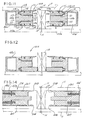
- Each arm carries at least one shear blade. As shown, and is preferred in most applications, however, each arm 45a", 45b" carries a pair of shear blades including an upper shear blade 203 and a lower shear blade 205.
- each shear blade 203 or 205 is somewhat longer than stringer 10 of pallet P and has its cutting edge facing inwardly toward its respective stringer. Further, each blade is slidably carried on its respective arm for both longitudinal movement along the length of its arm and for transverse movement toward and away from its respective stringer. As shown, each blade is retained in sliding relation on its arm by means of a retainer plate 207.
- each of the blades are angled at, for example, a 45 angle and constitute a front cam surface 209 and a rear cam surface 211.
- a cam actuator as generally indicated at 213, is provided for the simultaneous closing of the upper shear blades of nail cutter 201.
- a similar cam actuator 214 (see FIG. 15) is provided for actuating the lower blades.
- Actuator 213 includes a cam member 215 movable in generally longitudinal direction relative to its respective shear blades and to its respective arms 45a", 45b" from a first or open position (as shown in FIG. 13a), to an intermediate position (as shown in FIG. 13b), and then to a second or closed position (as shown in FIG.
- Cam member 215 has a V-shaped cam surface 219 cooperable with the rear cam surfaces 211 of its respective shear blades.
- Arms 45a", 45b" each have an angled from surface 221 cooperable with the front cam surface 209 of the shear blades.
- Cam rollers 223 may be disposed between the cam surfaces of the blades and support arm cam surfaces thereby to facilitate closing of the shear blades.
- cam surfaces 211 and 219 cooperate to cammingly move the rear ends of the upper shear blades inwardly toward stringer 10 positioned therebetween.
- the upper shear blades are in general heightwise alignment with the interface between the upper face of stringer 10 and the bottom face of the upper or top slats 11 of the pallet P to be disassembled. In the manner, the cutting edges of the upper shear blades-enter the joint between the slats and the stringer so as to cuttingly engage nails N.
- the rear ends of the shear blades preferably (but not necessarily) overlap with one another with one blade on top so as to form a scissors-like cutting action on nails N. Also the rear ends of the shear blades come upon stops (not shown) so as to prevent excessive overlapping of the blades.
- suitable return springs 224 may be provided in cutter 201 so as to return the shear blades to their open position upon hydraulic cylinder unit 215 being returned to its first or open position. It will be understood that the bottom shear blades are constructed and operated in the same manner as the above-described top shear blade.
- table 7 is raised so that the bottom blades 205 are in alignment with the bottom interface between stringers 10 and bottom slats 11 of the pallet.
- the bottom blades may be closed in the same manner as above described so as to cut bottom nails N. It can thus be readily appreciated that both the top and bottom nails of pallet P may be cut without the necessity of handling the pallet or repositioning the pallet relative to the nail cutters other than the above described heightwise adjustment of table 7.
- abutment member'23' is mounted on compression coil springs 301 which permit it to move into a retracted position within a recess 303 provided in the front portion of table 7 upon the raising of the table so as to effect alignment of the bottom interface between the pallet slats and the stringers with the lower shear blades of the nail cutters.
- either additional nail cutting means 9, 101, or 201 may be provided so as to simultaneously effect the cutting of all slats from the stringers, or after cutting some of the slats from the stringers, the table 7 may be returned to its retracted position, clamp 25 loosened, and the pallet shifted transversely relative to the nail cutter so as to align another of the nail cutters up with the other stringers of the pallet.
- only one of the above-described nailing cutters need be used and that the pallet being disassembled may be shifted in transverse direction so as to align its stringers with the one nailing cutter.
- apparatus 1 has its rails 5 on the outside of its frame. It will be appreciated that the rails'could be moved inboard of the frame so as to expose winch assembly 33 and hydraulic cylinders 21 and 29 for more ready servicing thereof.
- the term "shear” is used in a generic sense to refer to any cutting or breaking action of nails N holding the slats to the stringers of a pallet.
Landscapes
- Engineering & Computer Science (AREA)
- Mechanical Engineering (AREA)
- Dovetailed Work, And Nailing Machines And Stapling Machines For Wood (AREA)
Applications Claiming Priority (2)
| Application Number | Priority Date | Filing Date | Title |
|---|---|---|---|
| US91517 | 1979-11-05 | ||
| US06/091,517 US4320570A (en) | 1979-11-05 | 1979-11-05 | Apparatus for disassembling wooden pallets |
Publications (1)
| Publication Number | Publication Date |
|---|---|
| EP0028534A1 true EP0028534A1 (de) | 1981-05-13 |
Family
ID=22228203
Family Applications (1)
| Application Number | Title | Priority Date | Filing Date |
|---|---|---|---|
| EP19800303943 Withdrawn EP0028534A1 (de) | 1979-11-05 | 1980-11-05 | Vorrichtung und Verfahren zum Abbauen von Holzpaletten |
Country Status (3)
| Country | Link |
|---|---|
| US (1) | US4320570A (de) |
| EP (1) | EP0028534A1 (de) |
| CA (1) | CA1170021A (de) |
Cited By (5)
| Publication number | Priority date | Publication date | Assignee | Title |
|---|---|---|---|---|
| FR2614825A1 (fr) * | 1987-05-06 | 1988-11-10 | Bensimon Gerard | Machine pour le demontage des palettes |
| EP0207658A3 (de) * | 1985-06-20 | 1989-02-15 | Raymond E. James | Motorisch angetriebenes Werkzeug zum Reparieren einer Palette |
| WO1994007647A1 (en) * | 1992-10-06 | 1994-04-14 | Pick, David, William | Apparatus for and method of dismantling a pallet |
| FR2711088A1 (fr) * | 1993-10-15 | 1995-04-21 | Nadaud Didier | Démonte-palettes. |
| NL2003646C2 (nl) * | 2009-10-15 | 2011-04-18 | Douna Engineering B V | Pallet-reparatie inrichting en werkwijze voor het repareren van een pallet. |
Families Citing this family (26)
| Publication number | Priority date | Publication date | Assignee | Title |
|---|---|---|---|---|
| US4435892A (en) | 1979-11-05 | 1984-03-13 | Williams Panel Board Company | Method of disassembling wooden pallets |
| US4586235A (en) * | 1985-03-14 | 1986-05-06 | Enzo Benvenuto | Pallet stripper apparatus |
| US4649617A (en) * | 1985-06-14 | 1987-03-17 | Hufnagel Paul L | Machine for partially or completely disassembling wood pallets |
| US4750255A (en) * | 1985-06-14 | 1988-06-14 | Hufnagel Paul L | Machine for disassembling wood pallets |
| US5201110A (en) * | 1986-08-22 | 1993-04-13 | Bane Marvin L | Pallet dismantler |
| US4757599A (en) * | 1986-08-22 | 1988-07-19 | Bane Marvin L | Pallet dismantler |
| GB8827341D0 (en) * | 1988-11-23 | 1988-12-29 | Gkn Chep Ltd | Pallet cutting machine |
| US5243751A (en) * | 1989-08-09 | 1993-09-14 | Industrial Resources Of Michigan | Single-pass pallet disassembler with self-adjusting head |
| US4945626A (en) * | 1989-08-09 | 1990-08-07 | Industrial Resources Of Michigan | Single-pass pallet disassembler with self-adjusting head |
| US5105526A (en) * | 1989-08-09 | 1992-04-21 | Industrial Resources Of Michigan | Shearing blade for pallet disassembler |
| US5211094A (en) * | 1991-11-15 | 1993-05-18 | Johnson John L | Cutter head for pallet dismantling machine |
| WO1994003036A1 (en) * | 1992-07-24 | 1994-02-03 | Tessera, Inc. | Semiconductor connection components and methods with releasable lead support |
| US5307554A (en) * | 1992-12-02 | 1994-05-03 | John L. Johnson | Pallet dismantling machine and cutter head assembly therefor |
| WO1997006932A1 (en) * | 1995-08-15 | 1997-02-27 | Solid Waste Management Systems, Inc. | An apparatus and method for processing palletized containers |
| CA2173163C (en) * | 1996-03-26 | 2004-06-29 | Gordon E. Mason | Pallet disassembler |
| US5848459A (en) * | 1996-05-22 | 1998-12-15 | Juston Minick | Pallet end board remover |
| US5937276A (en) * | 1996-12-13 | 1999-08-10 | Tessera, Inc. | Bonding lead structure with enhanced encapsulation |
| US6058586A (en) * | 1998-05-18 | 2000-05-09 | Pallet Recycling, Inc. | Method and apparatus for repairing pallets |
| US6032351A (en) * | 1998-05-18 | 2000-03-07 | Pallet Recycling, Inc. | Machine for removing stringers from pallets |
| US6154955A (en) * | 1998-05-18 | 2000-12-05 | Pallet Recycling, Inc. | Machine for removing deckboards from pallets |
| US6293000B1 (en) * | 2000-02-01 | 2001-09-25 | Smetco, Inc. | Table saw construction for dismantling of pallets |
| US6687970B2 (en) * | 2002-04-30 | 2004-02-10 | Ronald L. Waechter | Method and device for removing pallet runners |
| US8752457B1 (en) * | 2007-03-20 | 2014-06-17 | Pellet Recyclers LLC | Pallet dismantler |
| SE534491C2 (sv) * | 2010-11-19 | 2011-09-06 | Yaskawa Nordic Ab | Anordning för demontering av valda delar av sammanfogade lastpallar |
| WO2014022470A1 (en) * | 2012-07-31 | 2014-02-06 | CLM Pallet Recycling, Inc. | Pallet refurbishing apparatus and method |
| CN119115397B (zh) * | 2024-11-14 | 2025-02-18 | 山东鑫木汽车配件有限公司 | 一种车辆桥壳组队工装 |
Citations (2)
| Publication number | Priority date | Publication date | Assignee | Title |
|---|---|---|---|---|
| US3869780A (en) * | 1973-11-01 | 1975-03-11 | Oscar H Ginnow | Unnailer |
| US4152819A (en) * | 1977-07-01 | 1979-05-08 | Conkle Neil E | Machine for disassembling wood pallets |
Family Cites Families (9)
| Publication number | Priority date | Publication date | Assignee | Title |
|---|---|---|---|---|
| US2593843A (en) * | 1949-12-05 | 1952-04-22 | Valley Products Corp | Crate disassembling and salvaging machine |
| US3512242A (en) * | 1968-03-05 | 1970-05-19 | Harvis Sons Inc C | Pallet dismantling apparatus |
| US3740815A (en) * | 1971-09-13 | 1973-06-26 | T Campbell | Pallet stringer puller |
| US3846890A (en) * | 1974-01-02 | 1974-11-12 | R Bielkiewicz | Pallet disassembly machine |
| SU632569A1 (ru) * | 1975-06-12 | 1978-11-15 | Ovchinnikov Anatolij M | Устройство дл разборки дерев нной тары |
| US3991459A (en) * | 1975-12-10 | 1976-11-16 | Rapp Kenneth K | Pallet disassembling apparatus |
| US4089098A (en) * | 1977-03-11 | 1978-05-16 | Demarco Charles C | Prying machine for dismantling pallets and the like |
| US4112578A (en) * | 1977-07-08 | 1978-09-12 | Curfman, Brainerd, Harris, Bell, Weigans And Depew | Apparatus for disassembling pallets |
| US4241495A (en) * | 1979-01-19 | 1980-12-30 | Dale Wakeem | Method and apparatus for disassembling wooden pallets |
-
1979
- 1979-11-05 US US06/091,517 patent/US4320570A/en not_active Expired - Lifetime
-
1980
- 1980-11-04 CA CA000363948A patent/CA1170021A/en not_active Expired
- 1980-11-05 EP EP19800303943 patent/EP0028534A1/de not_active Withdrawn
Patent Citations (2)
| Publication number | Priority date | Publication date | Assignee | Title |
|---|---|---|---|---|
| US3869780A (en) * | 1973-11-01 | 1975-03-11 | Oscar H Ginnow | Unnailer |
| US4152819A (en) * | 1977-07-01 | 1979-05-08 | Conkle Neil E | Machine for disassembling wood pallets |
Cited By (5)
| Publication number | Priority date | Publication date | Assignee | Title |
|---|---|---|---|---|
| EP0207658A3 (de) * | 1985-06-20 | 1989-02-15 | Raymond E. James | Motorisch angetriebenes Werkzeug zum Reparieren einer Palette |
| FR2614825A1 (fr) * | 1987-05-06 | 1988-11-10 | Bensimon Gerard | Machine pour le demontage des palettes |
| WO1994007647A1 (en) * | 1992-10-06 | 1994-04-14 | Pick, David, William | Apparatus for and method of dismantling a pallet |
| FR2711088A1 (fr) * | 1993-10-15 | 1995-04-21 | Nadaud Didier | Démonte-palettes. |
| NL2003646C2 (nl) * | 2009-10-15 | 2011-04-18 | Douna Engineering B V | Pallet-reparatie inrichting en werkwijze voor het repareren van een pallet. |
Also Published As
| Publication number | Publication date |
|---|---|
| US4320570A (en) | 1982-03-23 |
| CA1170021A (en) | 1984-07-03 |
Similar Documents
| Publication | Publication Date | Title |
|---|---|---|
| US4320570A (en) | Apparatus for disassembling wooden pallets | |
| US4346506A (en) | Pallet machine | |
| US4241495A (en) | Method and apparatus for disassembling wooden pallets | |
| US4435892A (en) | Method of disassembling wooden pallets | |
| US4262572A (en) | Log sawing apparatus | |
| US4489874A (en) | Pallet manufacturing machine | |
| CA2093477C (en) | Hairpin spike pulling tool and machine therefor | |
| US4152819A (en) | Machine for disassembling wood pallets | |
| EP0708741B1 (de) | Vorrichtung zum teilen von verbundglas | |
| DE3504581A1 (de) | Steinsaege zum zerteilen von steinplatten oder dergl. | |
| AU2009200461A1 (en) | A Sawmill | |
| US6092709A (en) | Machine for advancing a sheet metal strip in measured increments | |
| US4945626A (en) | Single-pass pallet disassembler with self-adjusting head | |
| US6609547B1 (en) | Log splitter attachment for a skid loader | |
| US4221246A (en) | Floor joist machine | |
| US20060231370A1 (en) | Board Lumber Position Fence | |
| US5463808A (en) | Discrete pallet deck board remover machine | |
| US4702403A (en) | Rail breaker | |
| US4081009A (en) | Method and apparatus for severing fibrous articles such as trees | |
| CA2110476C (en) | Pallet dismantling machine and cutter head assembly therefor | |
| US4317398A (en) | Sawmill apparatus having cant supporting means | |
| US3978783A (en) | Apparatus for fabricating wood structures | |
| US5243751A (en) | Single-pass pallet disassembler with self-adjusting head | |
| US5408907A (en) | Traversing circular saw | |
| US5894873A (en) | Apparatus for processing logs |
Legal Events
| Date | Code | Title | Description |
|---|---|---|---|
| PUAI | Public reference made under article 153(3) epc to a published international application that has entered the european phase |
Free format text: ORIGINAL CODE: 0009012 |
|
| AK | Designated contracting states |
Designated state(s): DE FR GB IT |
|
| 17P | Request for examination filed |
Effective date: 19811106 |
|
| STAA | Information on the status of an ep patent application or granted ep patent |
Free format text: STATUS: THE APPLICATION IS DEEMED TO BE WITHDRAWN |
|
| 18D | Application deemed to be withdrawn |
Effective date: 19830526 |
|
| RIN1 | Information on inventor provided before grant (corrected) |
Inventor name: WILLIAMS, LONNIE M. |