EP0030738B1 - Halterung für Vorschaltgeräte von Leuchtstofflampen - Google Patents
Halterung für Vorschaltgeräte von Leuchtstofflampen Download PDFInfo
- Publication number
- EP0030738B1 EP0030738B1 EP80107980A EP80107980A EP0030738B1 EP 0030738 B1 EP0030738 B1 EP 0030738B1 EP 80107980 A EP80107980 A EP 80107980A EP 80107980 A EP80107980 A EP 80107980A EP 0030738 B1 EP0030738 B1 EP 0030738B1
- Authority
- EP
- European Patent Office
- Prior art keywords
- choke coil
- holding
- profile
- holding parts
- coil
- Prior art date
- Legal status (The legal status is an assumption and is not a legal conclusion. Google has not performed a legal analysis and makes no representation as to the accuracy of the status listed.)
- Expired
Links
- 238000013016 damping Methods 0.000 claims description 7
- 238000004804 winding Methods 0.000 claims description 3
- 210000001331 nose Anatomy 0.000 claims 3
- 230000010355 oscillation Effects 0.000 claims 1
- 230000002093 peripheral effect Effects 0.000 claims 1
- 230000000694 effects Effects 0.000 description 5
- 230000004907 flux Effects 0.000 description 5
- 238000009434 installation Methods 0.000 description 3
- 238000004519 manufacturing process Methods 0.000 description 3
- 230000005540 biological transmission Effects 0.000 description 2
- 238000010276 construction Methods 0.000 description 2
- 238000005520 cutting process Methods 0.000 description 2
- 239000004033 plastic Substances 0.000 description 2
- 125000006850 spacer group Chemical group 0.000 description 2
- 238000013459 approach Methods 0.000 description 1
- 239000011324 bead Substances 0.000 description 1
- 238000005452 bending Methods 0.000 description 1
- 238000005266 casting Methods 0.000 description 1
- 230000008602 contraction Effects 0.000 description 1
- 230000008878 coupling Effects 0.000 description 1
- 238000010168 coupling process Methods 0.000 description 1
- 238000005859 coupling reaction Methods 0.000 description 1
- 230000035622 drinking Effects 0.000 description 1
- 238000007667 floating Methods 0.000 description 1
- 239000002184 metal Substances 0.000 description 1
- 238000000034 method Methods 0.000 description 1
- 238000005293 physical law Methods 0.000 description 1
- 238000003825 pressing Methods 0.000 description 1
- 239000011347 resin Substances 0.000 description 1
- 229920005989 resin Polymers 0.000 description 1
- 239000000725 suspension Substances 0.000 description 1
Images

Classifications
-
- F—MECHANICAL ENGINEERING; LIGHTING; HEATING; WEAPONS; BLASTING
- F21—LIGHTING
- F21V—FUNCTIONAL FEATURES OR DETAILS OF LIGHTING DEVICES OR SYSTEMS THEREOF; STRUCTURAL COMBINATIONS OF LIGHTING DEVICES WITH OTHER ARTICLES, NOT OTHERWISE PROVIDED FOR
- F21V23/00—Arrangement of electric circuit elements in or on lighting devices
- F21V23/02—Arrangement of electric circuit elements in or on lighting devices the elements being transformers, impedances or power supply units, e.g. a transformer with a rectifier
-
- H—ELECTRICITY
- H01—ELECTRIC ELEMENTS
- H01F—MAGNETS; INDUCTANCES; TRANSFORMERS; SELECTION OF MATERIALS FOR THEIR MAGNETIC PROPERTIES
- H01F27/00—Details of transformers or inductances, in general
- H01F27/33—Arrangements for noise damping
Definitions
- the invention relates to a holder for a choke coil as a ballast for elongated fluorescent lamps, the choke coil having an elongated magnetic circuit and associated coil being installed in an elongated carrier profile of the fluorescent lamp, on which holding profiles are provided on the two end faces of the choke coil and are firmly connected to the carrier profile. and on both end faces of the choke coil are firmly attached to this holding parts, the choke coil being mounted at a distance from the carrier profile.
- Ballasts for gas discharge lamps are subject to force effects in quadratic dependence on the temporally changing magnetic flux when operated on AC voltage due to the physical laws.
- the main effect on the magnetic circuit is therefore twice the network frequency or a multiple thereof, caused by the odd harmonics and, depending on the design, by bending resonances.
- the inherent noises of the ballast are damped in such a way that they are no longer audible even at a short distance from the lamp.
- low vibrational energies particularly at the attachment point, can be transmitted to the luminaire housing, even amplified as a result of resonances.
- a holder of the type described above, but with a compact magnetic circuit, has become known from DE-U-7 416 032.
- the holding parts at the front ends of the inductor are there directly and firmly connected to the holding profiles on the support profile designed as a support plate, so that vibrations of the inductor are fully transmitted to the support plate.
- a ballast has become known from US-A-4 000 406, the compact magnetic circuit of which is embedded in casting resin and surrounded by a housing. Holding parts are fastened to the housing on its long sides, which are screwed to holding profiles on the lamp housing with the interposition of compressed rubber inserts. Complete decoupling of vibrations between the housing and the lamp housing is not possible with this arrangement and structure, since the screw connection inevitably leads to at least partial vibration transmission.
- the vibration-damping elements of the known type and shape can no longer be used.
- a pressing bracket as a result of all-round installation of the luminaire profile on the ballast in the novel ballasts in the extremely elongated form in terms of noise no longer makes sense, because with this type of installation, the vibrational energies are inevitably transmitted to the luminaire housing and especially when mounting on or in Furniture may experience additional disruptive noises due to furniture resonance.
- the invention has for its object to design the bracket for the attachment of a ballast of the type mentioned so that a vibration coupling between the inductor and the support profile of the fluorescent lamp is completely avoided.
- This object is achieved in that the holding parts and the holding profiles are connected to one another in a decoupling manner in terms of vibrations, wherein vibration-damping inserts or point-shaped or cutting-like lugs are arranged on all circumferential sides of the holding parts between them.
- vibration-damping inserts or pointed or cutting-shaped lugs acting as the only connection to the holding profiles outside the core package of the choke coil result in vibrations of the core package in the transverse direction of the core package not being transmitted to the holding profiles due to the Maxwell forces. Since the choke coil can move freely in the longitudinal direction with respect to the holding profiles, contraction forces in the layer direction cannot lead to vibration transmission.
- the holding profile is box-shaped, surrounding the winding head of the coil, and additionally has pointed or cutting-shaped lugs on the end faces.
- the holding parts advantageously have pin-shaped lugs which are mounted in cutting-shaped bearings in the holding profiles. Vibration-damping rubber parts can be provided between the pin-shaped lugs and the cutting-shaped bearings.
- the pointed or cutting-shaped lugs are expediently attached to the holding parts which are firmly connected to the choke coil.
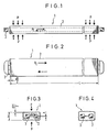
- Figures 1 to 4 show a choke coil 1 as a ballast in an extremely elongated form with a magnetic circuit 2 and coil 3.
- the aspect ratio of the choke coil 1 is approximately 2: 1, the width of the choke coil 1 being approximately the diameter of the one in FIGS 4 corresponds not shown fluorescent lamp of 26 mm.
- the magnetic circuit 1 contains an air gap ⁇ .
- the magnetic flux 0 passes through the coil 3 as well as the air gap ⁇ .
- magnetic force effects occur as a function of the square and cause the air gap 6 to contract by the size dH, where H is the height of the choke coil 1.
- 3 shows the resulting deformation of the choke coil 1 under the effect of the force P acting uniformly over the entire length per chunk coil 1 per unit length of the choke coil 1.
- FIG. 4 with a corresponding force effect of 0, the relaxation in the form of an overshoot of the dimensions of the choke coil 1 at the moment the flow 0 passes through zero is shown.
- the length of the choke coil 1 also tries to shorten as a function of time of the magnetic flux with the force P L , namely by the length d1 in each half-wave of the magnetic flux.
- the magnetic circuit 2 of the choke coil 1 has a length L.
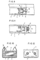
- a holding part 7 is attached to the end faces of the choke coil 1.
- Vibration-absorbing rubber inserts 8 are attached between the holding parts 7 and the holding profiles 6, surrounding the holding parts 7.
- the holding parts 7 are seated in the holding profiles 6 such that a longitudinal expansion of the inductor 1 is possible without touching the holding profiles 6 on the end faces.
- the rubber inserts 8 ensure that the choke coil 1 is mounted in a vibration-decoupled manner in the holding profiles 6 in such a way that the choke coil 1 is at a distance a to the side from the carrier profile 4 of the fluorescent lamp 5 and a distance b is at the top and bottom on the broad side .
- a vibration-decoupling mounting of the inductor 1 is hereby achieved.
- pointed or cutting-shaped lugs 9 are attached to the holding profiles 6, which only have their tips or cutting edges rest on the holding parts 7.
- the distance between the pointed or cutting-shaped lugs 9 from the end faces of the holding parts 7 is a total of s.
- the pointed or cutting-shaped lugs 9 allow the choke coil 1 to move freely in the holding profiles 6 in a vibration-decoupled mounting.
- the embodiment according to FIGS. 7 and 8 is particularly suitable for the design of the plastic holder parts.
- two pin-shaped projections 10 are attached to the holding parts 7 connected to the choke coil 1, which protrusions end in corresponding bores 11 of the with the support profile 4 Project fluorescent lamp connected support profile 6.
- the approaches 10 are stored in the bores 11 in a cutting shape.
- the length fixation of the choke coil 1 is also set to the dimension s, whereby a lug 9 attached to the holding part 7 can only result in point contact with the holding profile 6 at one point, which ensures an evasive decoupling.
- the holding profiles 6 are in turn box-shaped, surrounding the winding head of the coil 3, so that when the holding profile 6 is made of plastic, protection against accidental contact of the live parts of the choke coil 1 is simultaneously provided.
- the holding profile 6 has projections 12 pointing upwards and sits in a form-fitting manner in the carrier profile 4 of the fluorescent lamp.
- a recess 13 is provided in at least one of the extensions 12, into which the carrier profile 4 of the fluorescent lamp projects by flanging.
- This embodiment of the holder is of particular advantage for series production, because not only are there no additional means for fastening the inductor 1, such as screws and nuts, but also the production and the method for the arrangement of the elongated inductor 1 for low-noise lamps in particular is simple.
- each holding part 7 projecting therefrom.
- the holding profile 6 is designed as a U-shaped end part made of metal, for example connected to the carrier profile 4 of the fluorescent lamp by means of screws or points. Between the pin-shaped lugs 10 and the cutting-shaped mounting in the bores 11 of the holding profile 6, the vibration-damping rubber parts 14 surrounding the cylindrical lugs 10 are provided here.
Landscapes
- Engineering & Computer Science (AREA)
- Power Engineering (AREA)
- General Engineering & Computer Science (AREA)
- Arrangement Of Elements, Cooling, Sealing, Or The Like Of Lighting Devices (AREA)
- Housings And Mounting Of Transformers (AREA)
Description
- Die Erfindung betrifft eine Halterung für eine Drosselspule als Vorschaltgerät für langgestreckte Leuchtstofflampen, wobei die Drosselspule mit langgestrecktem magnetischen Kreis und zugehöriger Spule in ein langgestrecktes Trägerprofil der Leuchtstofflampe eingebaut ist, an dem an den beiden Stirnseiten der Drosselspule mit dem Trägerprofil fest verbundene Halteprofile vorgesehen sind, und an beiden Stirnseiten der Drosselspule fest mit dieser verbundene Halteteile angebracht sind, wobei die Drosselspule im Abstand vom Trägerprofil gelagert ist.
- Vorschaltgeräte für Gasentladungslampen, insbesondere Leuchtstofflampen, unterliegen bei Betrieb an Wechselspannung aufgrund der physikalischen Gesetze Kraftwirkungen in quadratischer Abhängigkeit des zeitlich wechselnden magnetischen Flusses. Die Haupteinwirkung auf den magnetischen Kreis erfolgt demnach mit doppelter Netzfrequenz bzw. mit einem Vielfachen derselben, hervorgerufen durch die ungeradzahligen Oberwellen, und, je nach konstruktivem Aufbau, durch Biegeresonanzen.
- Durch die Ausgestaltung des konstruktiven Aufbaus und durch verschiedene Fertigungsverfahren, wie Tränken unter Vakuum, werden die Eigengeräusche des Vorschaltgeräts derart gedämpft, dass sie bereits in geringem Abstand von der Leuchte nicht mehr hörbar sind. Je nach Einbau des Vorschaltgeräts in die Leuchte können sich aber geringe Schwingungsenergien, insbesondere an der Befestigungsstelle, auf das Leuchtengehäuse übertragen, ja sogar infolge von Resonanzen verstärken.
- Eine Halterung der eingangs beschriebenen Art, jedoch mit gedrungenem magnetischen Kreis, ist durch das DE-U-7 416 032 bekannt geworden. Die Halteteile an den Stirnenden der Drosselspule sind dort unmittelbar und fest mit den Halteprofilen an dem als Trägerplatte ausgebildeten Trägerprofil verbunden, so dass Schwingungen der Drosselspule voll auf die Trägerplatte übertragen werden.
- Durch die US-A-4 000 406 ist ein Vorschaltgerät bekannt geworden, dessen gedrungen aufgebauter magnetischer Kreis in Giessharz eingebettet und von einem Gehäuse umgeben ist. An dem Gehäuse sind an dessen Längsseiten Halteteile befestigt, die mit Halteprofilen am Lampengehäuse unter Zwischenfügung von zusammengepressten Gummieinlagen verschraubt sind. Eine vollständige Schwingungsentkopplung zwischen Gehäuse und Lampengehäuse ist durch diese Anordnung und Aufbau nicht möglich, da die Verschraubung zwangsläufig zu wenigstens einer teilweisen Schwingungsübertragung führt.
- Durch die DE-B-1 764 154 ist es bekannt geworden, an den Ecken des Kernpakets eines Vorschaltgeräts Distanzhalter zum Gehäuse in Form von Sickungen oder vorstehenden Formteilen anzubringen. Eine vollständige Schwingungsentkopplung ist damit nicht möglich, da die Distanzhalter am Kernpaket selbst angreifen.
- Um eine kompakte, materialsparende und ansprechende Form der Leuchte mit Leuchtstofflampen mit einem Rohrdurchmesser von 26 mm gegenüber den bisherigen Standardlampen mit einem Rohrdurchmesser von 38 mm zu ermöglichen, sind die schwingungsdämpfenden Elemente der bekannten Art und Form nicht mehr verwendbar. Beispielsweise zeigt sich eine pressende Halterung infolge allseitiger Anlage des Leuchtenprofils am Vorschaltgerät bei den neuartigen Vorschaltgeräten in der extrem langgestreckten Form hinsichtlich der Geräusche nicht mehr als sinnvoll, weil bei dieser Montageart die Schwingungsenergien unweigerlich auf das Leuchtengehäuse übertragen werden und insbesondere bei der Montage an oder in Möbeln zusätzliche störende Geräusche aufgrund von Resonanzen der Möbel auftreten können.
- Der Erfindung liegt die Aufgabe zugrunde, die Halterung für die Befestigung eines Vorschaltgerätes der eingangs genannten Art so auszugestalten, dass eine Schwingungskopplung zwischen der Drosselspule und dem Trägerprofil der Leuchtstofflampe vollständig vermieden wird.
- Diese Aufgabe wird dadurch gelöst, dass die Halteteile und die Halteprofile schwingungsmässig entkoppelnd miteinander verbunden sind, wobei zwischen diesen schwingungsdämpfende Einlagen oder spitzen- bzw. schneidenförmige Nasen an allen Umfangsseiten der Halteteile angeordnet sind.
- Die ausserhalb des Kernpakets der Drosselspule angreifenden schwingungsdämpfenden Einlagen oder spitzen- bzw. schneidenförmigen Nasen als einzige Verbindung zu den Halteprofilen führen dazu, dass Schwingungen des Kernpakets in Querrichtung des Kernpakets aufgrund der Maxwellkräfte nicht auf die Halteprofile übertragen werden. Da sich die Drosselspule gegenüber den Halteprofilen in Längsrichtung frei bewegen kann, können auch Kontraktionskräfte in Schichtrichtung nicht zu einer Schwingungsübertragung führen.
- Das Halteprofil ist gemäss einer besonderen Ausbildung der Erfindung kastenförmig, den Wickelkopf der Spule umgebend ausgebildet und weist zusätzlich spitzen- bzw. schneidenförmige Nasen an den Stirnseiten auf.
- Vorteilhaft weisen die Halteteile stiftförmige Ansätze auf, welche in schneidenförmigen Lagerungen in den Halteprofilen gelagert sind. Zwischen den stiftförmigen Ansätzen und den schneidenförmigen Lagerungen können schwingungsdämpfende Gummiteile vorgesehen sein.
- Die spitzen- oder schneidenförmigen Nasen sind zweckmässig an den mit der Drosselspule fest verbundenen Halteteilen angebracht.
- Die Erfindung ist im folgenden anhand von in den Zeichnungen dargestellten Ausführungsbeispielen näher erläutert. In den Zeichnungen zeigen
- Fig. 1 eine langgestreckte Drosselspule in Seitenansicht,
- Fig. 2 die Drosselspule nach Fig. 1 in Draufsicht,
- Fig. 3 einen Querschnitt durch die Drosselspule nach Fig. 1 und 2 mit angedeutetem einen extremen Schwingungszustand,
- Fig. 4 einen Querschnitt wie in Fig. 3 für den anderen extremen Schwingungszustand,
- Fig. 5 eine Seitenansicht einer Drosselspule mit Halterung,
- Fig. 6 einen Querschnitt durch die Drosselspule nach Fig. 5,
- Fig. 7 ein anderes Ausführungsbeispiel einer Drosselspule mit Halterung,
- Fig. 8 einen Querschnitt durch die Drosselspule nach Fig. 7,
- Fig. 9 ein weiteres Ausführungsbeispiel für eine Halterung einer Drosselspule,
- Fig. 10 einen Querschnitt durch die Halterung nach Fig. 9,
- Fig. 11 ein viertes Ausführungsbeispiel für eine Halterung einer Drosselspule, und
- Fig. 12 eine Draufsicht auf die Halterung nach Fig. 11.
- Die Figuren 1 bis 4 zeigen eine Drosselspule 1 als Vorschaltgerät in extrem langgestreckter Form mit magnetischem Kreis 2 und Spule 3. Das Seitenverhältnis der Drosselspule 1 ist etwa 2:1, wobei die Breite der Drosselspule 1 etwa dem Durchmesser der in den Fig. 1 bis 4 nicht dargestellten Leuchtstofflampe von 26 mm entspricht. Der magnetische Kreis 1 beinhaltet einen Luftspalt Δ.
- In der Bauform der Mantelbauweise der Drosselspule 1 durchsetzt der magnetischen Fluss 0 die Spule 3 wie auch den Luftspalt Δ. Entsprechend dem Verlauf des magnetischen Flusses 0 treten in quadratischer Abhängigkeit von diesem magnetische Kraftwirkungen auf und bringen den Luftspalt 6 zum Zusammenziehen um die Grösse dH, wobei H die Höhe der Drosselspule 1 ist. In Fig. 3 ist gestrichelt die sich hieraus ergebende Verformung der Drosselspule 1 unter Wirkung der pro Längeneinheit der Drosselspule 1 über die gesamte Länge gleichmässig auf die Drosselspule 1 einwirkenden Kraft P gezeigt. In Fig. 4 ist bei entsprechender Kraftwirkung von 0 das Entspannen in Form eines Überschwingens der Abmessungen der Drosselspule 1 im Augenblick des Nulldurchgangs des Flusses 0 dargestellt.
- Auch die Länge der Drosselspule 1 versucht sich in zeitlicher Abhängigkeit des magnetischen Flusses mit der Kraft PL zu verkürzen, und zwar in jeder Halbwelle des magnetischen Flusses um die Länge dl.
- In den Fig. 5 und 6 ist ein Ausführungsbeispiel einer Drosselspule 1 mit schwebender Aufhängung dargestellt. Auf beiden Stirnseiten der Drosselspule 1 ist je ein fest mit einem Trägerprofil 4 einer Leuchtstofflampe 5 verbundenes, kastenförmiges Halteprofil 6 angeordnet. Der magnetische Kreis 2 der Drosselspule 1 hat eine Länge L. An den Stirnseiten der Drosselspule 1 ist jeweils ein Halteteil 7 angebracht. Zwischen den Halteteilen 7 und den Halteprofilen 6 sind schwingungsdämpfende Einlagen 8 aus Gummi die Halteteile 7 umgebend angebracht. Die Halteteile 7 sitzen derart in den Halteprofilen 6, dass eine Längsausdehnung der Drosselspule 1 ohne Berührung der Halteprofile 6 auf den Stirnseiten möglich ist. Die Einlagen 8 aus Gummi sorgen dafür, dass die Drosselspule 1 schwingungsmässig entkuppelt in den Halteprofilen 6 derart gelagert ist, dass die Drosselspule 1 von dem Trägerprofil 4 der Leuchtstofflampe 5 seitlich jeweils einen Abstand a und an der Breitseite oben und unten jeweils einen Abstand b aufweist. Hierdurch wird eine schwingungsmässig entkoppelnde Lagerung der Drosselspule 1 erreicht.
- Die Halterung der Drosselspule 1 nach den Fig. 7 und 8 ist ähnlich der Halterung nach Fig. 5 und 6. Statt den Einlagen 8 aus Gummi sind spitzen- oder schneidenförmige Nasen 9 an den Halteprofilen 6 angebracht, welche lediglich mit ihren Spitzen bzw. Schneiden auf den Halteteilen 7 aufliegen. Der Abstand zwischen den spitzen- oder schneidenförmigen Nasen 9 von den Stirnseiten der Halteteile 7 beträgt insgesamt s. Die spitzen- bzw. schneidenförmigen Nasen 9 gestatten eine Freibewegung der Drosselspule 1 in den Halteprofilen 6 in schwingungsmässig entkuppelter Lagerung. Die Ausführungsform nach den Fig. 7 und 8 eignet sich besonders bei der Ausführung der Halterungsteile aus Kunststoff.
- Bei einer weiteren Ausführungsform einer Halterung für die Drosselspule 1 gemäss Fig. 9 und 10 sind an den mit der Drosselspule 1 verbundenen Halteteilen 7 je zwei stirnseitig wegragende stiftförmige Ansätze 10 mit vorzugsweise rundem Querschnitt angebracht, welche in entsprechende Bohrungen 11 des mit dem Trägerprofil 4 der Leuchtstofflampe verbundenen Halteprofils 6 hineinragen. Die Ansätze 10 sind in den Bohrungen 11 schneidenförmig gelagert. Die Längenfixierung der Drosselspule 1 ist ebenfalls auf das Mass s eingestellt, wobei sich durch eine an dem Halteteil 7 angebrachte Nase 9 nur an einer Stelle allenfalls eine punktförmige Berührung mit dem Halteprofil 6 ergeben kann, was eine ausweichende Entkopplung sicherstellt. Die Halteprofile 6 sind wiederum kastenförmig, den Wickelkopf der Spule 3 umgebend ausgeführt, so dass bei Ausbildung des Halteprofils 6 aus Kunststoff gleichzeitig ein Schutz gegen zufällige Berührung der spannungsführenden Teile der Drosselspule 1 entsteht. Das Halteprofil 6 weist nach oben gerichtete Fortsätze 12 auf und sitzt formschlüssig in dem Trägerprofil 4 der Leuchtstofflampe. In wenigstens einem der Fortsätze 12 ist eine Ausnehmung 13 vorgesehen, in welche das Trägerprofil 4 der Leuchtstofflampe durch Umbördeln hineinragt. Diese Ausführungsform der Halterung ist für die Serienfertigung von besonderem Vorteil, weil nicht nur zusätzliche Mittel für die Befestigung der Drosselspule 1, wie Schrauben und Muttern, zum Wegfall kommen, sondern die Herstellung und das Verfahren für die Anordnung der langgestreckten Drosselspule 1 für geräuscharme Leuchten besonders einfach ist.
- Bei der Ausführungsform nach den Fig. 11 und 12 sind ähnlich wie bei der Ausführungsform nach den Fig. 9 und 10 zwei stiftförmige Ansätze 10 an jedem Halteteil 7 von diesem wegragend angebracht. Das Halteprofil 6 ist als beispielsweise durch Schrauben oder Punkten mit dem Trägerprofil 4 der Leuchtstofflampe verbindenes, U-förmiges Stirnteil aus Metall ausgebildet. Zwischen den stiftförmigen Ansätzen 10 und der schneidenförmigen Lagerung in den Bohrungen 11 des Halteprofils 6 sind hier die zylindrischen Ansätze 10 umgebende schwingungsdämpfende Gummiteile 14 vorgesehen.
Claims (5)
Applications Claiming Priority (2)
| Application Number | Priority Date | Filing Date | Title |
|---|---|---|---|
| DE19792950726 DE2950726C2 (de) | 1979-12-17 | 1979-12-17 | Halterung für Vorschaltgeräte von Leuchtstofflampen |
| DE2950726 | 1979-12-17 |
Publications (2)
| Publication Number | Publication Date |
|---|---|
| EP0030738A1 EP0030738A1 (de) | 1981-06-24 |
| EP0030738B1 true EP0030738B1 (de) | 1984-02-15 |
Family
ID=6088712
Family Applications (1)
| Application Number | Title | Priority Date | Filing Date |
|---|---|---|---|
| EP80107980A Expired EP0030738B1 (de) | 1979-12-17 | 1980-12-17 | Halterung für Vorschaltgeräte von Leuchtstofflampen |
Country Status (4)
| Country | Link |
|---|---|
| EP (1) | EP0030738B1 (de) |
| DE (1) | DE2950726C2 (de) |
| HK (1) | HK13286A (de) |
| SG (1) | SG69785G (de) |
Families Citing this family (4)
| Publication number | Priority date | Publication date | Assignee | Title |
|---|---|---|---|---|
| AT380938B (de) * | 1984-12-21 | 1986-07-25 | Zumtobel Ag | Leuchte fuer leuchtstofflampen |
| DE3703005C1 (de) * | 1987-02-02 | 1988-08-04 | May & Christe Gmbh | Vorschaltgeraet fuer Gasentladungslampen |
| GB9126848D0 (en) * | 1991-12-18 | 1992-02-19 | Chelsing Assemblies Ltd | Electric component housing assembly |
| FI94568C (fi) * | 1992-12-15 | 1995-09-25 | Helvar Oy | Laitelma kuristimen äänitason alentamiseksi |
Citations (2)
| Publication number | Priority date | Publication date | Assignee | Title |
|---|---|---|---|---|
| DE1764154B1 (de) * | 1968-04-11 | 1972-07-13 | May & Christe Gmbh | Geraeuscharmes gasentladungslampen-vorschaltgeraet |
| US4000406A (en) * | 1974-11-29 | 1976-12-28 | Esquire, Inc. | Light fixture |
Family Cites Families (2)
| Publication number | Priority date | Publication date | Assignee | Title |
|---|---|---|---|---|
| DE7416032U (de) * | 1974-11-28 | Abke H | ||
| DE971196C (de) * | 1952-11-01 | 1958-12-24 | Vossloh Werke Gmbh | Armatur fuer die wasser- und gasdichte Installation von roehrenfoermigen Entladungslampen, wie Leuchtstofflampen oder -roehren |
-
1979
- 1979-12-17 DE DE19792950726 patent/DE2950726C2/de not_active Expired
-
1980
- 1980-12-17 EP EP80107980A patent/EP0030738B1/de not_active Expired
-
1985
- 1985-09-20 SG SG69785A patent/SG69785G/en unknown
-
1986
- 1986-02-27 HK HK13286A patent/HK13286A/xx not_active IP Right Cessation
Patent Citations (2)
| Publication number | Priority date | Publication date | Assignee | Title |
|---|---|---|---|---|
| DE1764154B1 (de) * | 1968-04-11 | 1972-07-13 | May & Christe Gmbh | Geraeuscharmes gasentladungslampen-vorschaltgeraet |
| US4000406A (en) * | 1974-11-29 | 1976-12-28 | Esquire, Inc. | Light fixture |
Also Published As
| Publication number | Publication date |
|---|---|
| DE2950726A1 (de) | 1981-07-23 |
| SG69785G (en) | 1986-11-21 |
| HK13286A (en) | 1986-03-07 |
| EP0030738A1 (de) | 1981-06-24 |
| DE2950726C2 (de) | 1983-07-28 |
Similar Documents
| Publication | Publication Date | Title |
|---|---|---|
| EP0198099B2 (de) | Schütz, insbesondere Hilfs- oder Motorschütz | |
| EP0135845A2 (de) | Vorrichtung zur Befestigung eines zwei im Abstandhintereinander angeordnete Tragflansche aufweisenden Gerätes | |
| DE102015220795A1 (de) | Kochfeldvorrichtung und Verfahren mit einer Kochfeldvorrichtung | |
| DE3311660A1 (de) | Axialventilator | |
| EP0030738B1 (de) | Halterung für Vorschaltgeräte von Leuchtstofflampen | |
| EP0793243A1 (de) | Transformator | |
| DE7535975U (de) | Kleintransformator | |
| DE19607092A1 (de) | Antennenspule für Fahrbereitschaftssysteme | |
| WO1999037003A1 (de) | Verbindungselement | |
| EP0338549B1 (de) | Schutzvorrichtung für ein Gebläse einer Brennkraftmaschine | |
| EP0927308A1 (de) | Rastvorrichtung für ein geradlinig verschiebbares bauteil | |
| DE4200659A1 (de) | Einbaustrahler | |
| DE3340904A1 (de) | Magnetisch betaetigte schaltanordnung, insbesondere luftschuetz | |
| DE2712721C2 (de) | Kohlehalter für Elektromotoren | |
| DE19850966A1 (de) | Antriebseinheit für eine Haarschneidemaschine | |
| EP0152096B1 (de) | Vorschaltgerät für Gasentladungslampen | |
| DE3347614A1 (de) | Leuchte mit verdrehgesicherter lampenfassung | |
| DE2438084B2 (de) | Elektromagnetisches Relais | |
| DE102004056316B4 (de) | Spulengestell | |
| DE8433089U1 (de) | Kochmulde | |
| DE10008242C2 (de) | Einbauvorrichtung für ein in einer Einbauöffnung zu befestigendes elektrisches Gerät | |
| DE2010981A1 (de) | Gehäuse fur elektrische Kleingerate | |
| DE1489321C (de) | Einbaufassung für kleine elektrische Lampen | |
| DE9416993U1 (de) | Einschaltwiderstandsanordnung für einen Hochspannungsschalter | |
| DE102020111516A1 (de) | Sicherheitsvorrichtung für elektrische Geräte |
Legal Events
| Date | Code | Title | Description |
|---|---|---|---|
| PUAI | Public reference made under article 153(3) epc to a published international application that has entered the european phase |
Free format text: ORIGINAL CODE: 0009012 |
|
| AK | Designated contracting states |
Designated state(s): FR GB IT NL |
|
| 17P | Request for examination filed |
Effective date: 19811006 |
|
| ITF | It: translation for a ep patent filed | ||
| GRAA | (expected) grant |
Free format text: ORIGINAL CODE: 0009210 |
|
| AK | Designated contracting states |
Designated state(s): FR GB IT NL |
|
| ET | Fr: translation filed | ||
| PLBE | No opposition filed within time limit |
Free format text: ORIGINAL CODE: 0009261 |
|
| STAA | Information on the status of an ep patent application or granted ep patent |
Free format text: STATUS: NO OPPOSITION FILED WITHIN TIME LIMIT |
|
| 26N | No opposition filed | ||
| ITTA | It: last paid annual fee | ||
| ITPR | It: changes in ownership of a european patent |
Owner name: CAMBIO RAGIONE SOCIALE;MAGNETEK MAY & CHRISTE GMBH |
|
| REG | Reference to a national code |
Ref country code: FR Ref legal event code: CD |
|
| NLT1 | Nl: modifications of names registered in virtue of documents presented to the patent office pursuant to art. 16 a, paragraph 1 |
Owner name: MAGNETEK MAY & CHRISTE GMBH TE OBERURSEL, BONDSREP |
|
| PGFP | Annual fee paid to national office [announced via postgrant information from national office to epo] |
Ref country code: GB Payment date: 19991208 Year of fee payment: 20 |
|
| PGFP | Annual fee paid to national office [announced via postgrant information from national office to epo] |
Ref country code: FR Payment date: 19991209 Year of fee payment: 20 |
|
| PGFP | Annual fee paid to national office [announced via postgrant information from national office to epo] |
Ref country code: NL Payment date: 19991231 Year of fee payment: 20 |
|
| PG25 | Lapsed in a contracting state [announced via postgrant information from national office to epo] |
Ref country code: GB Free format text: LAPSE BECAUSE OF EXPIRATION OF PROTECTION Effective date: 20001216 |
|
| PG25 | Lapsed in a contracting state [announced via postgrant information from national office to epo] |
Ref country code: NL Free format text: LAPSE BECAUSE OF EXPIRATION OF PROTECTION Effective date: 20001217 |
|
| REG | Reference to a national code |
Ref country code: GB Ref legal event code: PE20 Effective date: 20001216 |
|
| NLV7 | Nl: ceased due to reaching the maximum lifetime of a patent |
Effective date: 20001217 |