EP0031535A2 - Procédé pour la régénération cyclique de dispositifs pour l'adoucissement de l'eau et dispositif à commande à programme pour la mise en oeuvre du procédé - Google Patents
Procédé pour la régénération cyclique de dispositifs pour l'adoucissement de l'eau et dispositif à commande à programme pour la mise en oeuvre du procédé Download PDFInfo
- Publication number
- EP0031535A2 EP0031535A2 EP80107919A EP80107919A EP0031535A2 EP 0031535 A2 EP0031535 A2 EP 0031535A2 EP 80107919 A EP80107919 A EP 80107919A EP 80107919 A EP80107919 A EP 80107919A EP 0031535 A2 EP0031535 A2 EP 0031535A2
- Authority
- EP
- European Patent Office
- Prior art keywords
- water
- regeneration
- mass
- piston
- piston pump
- Prior art date
- Legal status (The legal status is an assumption and is not a legal conclusion. Google has not performed a legal analysis and makes no representation as to the accuracy of the status listed.)
- Granted
Links
Images

Classifications
-
- C—CHEMISTRY; METALLURGY
- C02—TREATMENT OF WATER, WASTE WATER, SEWAGE, OR SLUDGE
- C02F—TREATMENT OF WATER, WASTE WATER, SEWAGE, OR SLUDGE
- C02F1/00—Treatment of water, waste water, or sewage
- C02F1/42—Treatment of water, waste water, or sewage by ion-exchange
-
- B—PERFORMING OPERATIONS; TRANSPORTING
- B01—PHYSICAL OR CHEMICAL PROCESSES OR APPARATUS IN GENERAL
- B01J—CHEMICAL OR PHYSICAL PROCESSES, e.g. CATALYSIS OR COLLOID CHEMISTRY; THEIR RELEVANT APPARATUS
- B01J49/00—Regeneration or reactivation of ion-exchangers; Apparatus therefor
- B01J49/75—Regeneration or reactivation of ion-exchangers; Apparatus therefor of water softeners
Definitions
- the invention relates to a method for the cyclical regeneration of water softening systems, which comprise an exchange mass in a treatment tank and a regeneration agent in a storage tank, in which first the regeneration agent is passed from bottom to top through the exchange mass, then the wash mass is slowly washed with process water in the same direction of flow and then is backwashed vigorously, while in the treatment plant raw water is led from top to bottom as well as a program-controlled water softening system with a treatment tank holding an exchange mass, a storage tank holding a regenerating agent, a central control valve, the connections for raw water, process water, regenerating agent, to the upper and lower area of the Treatment tank includes, and a program control that a regeneration operation depending on the hardness of the raw water and the degree of exhaustion the exchange mass triggers and for regeneration flow first the regenerating agent from bottom to top through the exchange mass and subsequently Wash service water in the same direction of flow and then backwash it vigorously, in particular to carry out the process according to one of Claims 1 to 7.
- the time interval between two regenerations is preset in the time control.
- the actual process water withdrawal is therefore not taken into account, so that any remaining capacity of the exchanger mass which may still be present when the regeneration operation is started is lost.
- the operation is generally uneconomical and polluting, since for each regeneration operation an amount of regeneration agent must be used which corresponds to the regeneration of a completely exhausted exchanger mass. In the other extreme case, it can happen that the exchanger mass is already exhausted before the preset time has elapsed until the next regeneration, so that hardness breakthroughs occur.
- regeneration is triggered after a predetermined amount of process water has been drawn since the last regeneration, which can be determined by calculation depending on the capacity of the water softening system and the raw water hardness and entered into the program control.
- Systems of this type are technically complex and lead to long intervals between two regenerations if we remove little or no process water over a longer period of time. This then leads to strong contamination of the exchanger mass, which must be avoided in some areas of application, such as in the domestic and food technology sectors.
- regeneration operations can be triggered at a time when there is a high demand for hot water at the same time.
- the object of the invention is to further develop a method of the type mentioned at the beginning and a program-controlled water softening system of the type mentioned at the beginning such that hygienic operation is ensured at all times in an economical manner with the least possible environmental impact.
- this object is achieved in that in a method of the type mentioned both a maximum time interval and a maximum degree of exhaustion of the exchanger mass between two regenerations are preselected, that only one amount of regeneration agent proportional to the degree of exhaustion is used with each regeneration and that the regeneration agent is passed through the exchanger mass at such a low flow rate that the particle layers in the exchanger mass remain essentially unchanged and that in a program-controlled water softening system of the type mentioned at the outset, the program control comprises a timer which can be preset to a maximum time interval between two regenerations, a metering element which can be adjusted to the hardness of the raw water and which provides for each regeneration an amount of regenerating agent which is proportional to the degree of exhaustion of the exchange mass, d is a delay element which reduces the flow rate of the regenerant through the exchanger mass to such an extent that the particle layers in the exchanger mass remain essentially unchanged.
- a sufficiently low flow rate of the regenerating agent is achieved and maintained from bottom to top by the exchanger mass.
- the flow rate must be so low be that the individual particles of the exchanger mass do not noticeably change their position relative to one another, ie thin layers of the exchanger mass lying one above the other are not mixed with one another. Because the raw water enters the exchanger mass from above and is discharged below, the exchanger mass is first exhausted in its upper limit range and the exhausted mass of the exchanger mass slowly grows from top to bottom with a defined separation layer to the still active mass. Given the slow flow rate of the regeneration agent defined above, this displaces the water still present in the exchanger mass, without mixing with it and being further diluted.
- the regeneration agent thus reaches the upper area with the exhausted mass of the exchanger mass undiluted, ie with optimal concentration, and can thus regenerate it completely when flowing through.
- the invention makes it possible to manage with an amount of regenerating agent which is proportional to the degree of exhaustion of the exchange mass.
- the flow rate of the regeneration agent through the exchanger mass is preferably below or at most 1 m / h, which generally leads to a laminar flow.
- an amount of solvent water proportional to the quantity of process water withdrawn for the preparation of regenerating agent is branched off from the process water pipe between two regenerations and the dissolved regenerating agent is kept ready.
- a piston pump is preferably provided in connection with a three-way valve in which the piston is spring-biased against the inflow direction.
- the program control controlled by a water meter then switches the three-way valve between the service water line and the piston pump each time an impulse is received from the water meter and then switches it over after a predetermined time and connects the piston pump to the reservoir for the regenerant.
- a preset amount of solvent water is supplied to the reservoir for the regenerating agent with each pulse from the water meter, which is proportional to both the water hardness and the amount of used water withdrawn.
- a metering pump with a suction valve and a pressure valve for water treatment chemicals with the piston pump can be coupled, the metering piston of which can be actuated by the piston of the piston pump.
- a cover which supports the helical spring can advantageously be unscrewed from the piston pump, while the metering pump has a coupling member which can be screwed into the piston pump instead of the cover.
- the metering pump preferably has a metering piston which is biased against a fixed end stop by a helical spring and is moved against its own second end stop when the piston of the piston pump is moved against its second end stop.
- Such a metering pump then doses a fixed amount of water treatment chemicals into the service water line each time the water flow meter emits a pulse.
- Water treatment chemicals are thus metered in proportion to the tap water withdrawn, regardless of the water hardness to which the piston pump has been set.
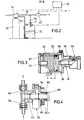
- a water softening system comprises a pressure vessel 10 as a treatment vessel, into which a .exchanger mass 12 is filled.
- a central control valve 14 which has connections for a raw water line 16, a process water line 18, a regenerant line 20, an access (not shown) to the upper region of the pressure container 10 and a connecting line 22 to the lower region of the pressure container 10.
- the water softening system comprises a storage container 24 for regenerating agent 26.
- the regenerating agent 26 is a solution of a regenerating salt 28 also stored in the storage container 24 with water which a spray head 30 arranged in the reservoir 24 emerges.
- a level gauge is also provided in the reservoir 24, which includes a float 32 and a switch 34.
- the spray head 30 is connected via a line to a connection of a three-way solenoid valve 36.
- the second connection of the three-way valve 36 is connected to a branch line of the hot water line 18.
- the third connection of the three-way valve 36 leads to a piston pump 38.
- a water flow meter 40 is inserted into the service water line 18.
- the water flow meter 40 can work according to the pulse technique, as described in DE-AS 23 00 6Q6.
- the water softening system has a program control 42 which is connected via electrical lines to the water meter 40, the three-way solenoid valve 36, the switch 34 of the level indicator and the central control valve 14.
- a piston pump 38 is shown in FIG. 3 with a piston 50 which is biased into an end position against an end stop 54 by means of a helical spring 52. Another end stop 57 is arranged on the same side of the piston 50 as the coil spring 52. The first end stop 54 can be displaced in the stroke direction of the piston by means of a fine adjustment device 56, which is shown as a micrometer screw.
- a connection opening 58 opens out on the side of the piston 50 remote from the coil spring 52 into the cylinder space of the piston pump 38.
- a metering pump 62 which comprises a coupling member 84.
- the coupling member 84 is formed with a thread that can be screwed to the housing of the piston pump 38.
- the housing of the piston pump 38 is formed on one end face with a cover 82 which supports the helical spring 52 and carries the second end stop 57 and which can be unscrewed from the housing of the piston pump 38.
- the metering pump 62 is screwed in with its coupling member 84.
- the coupling member 84 then supports the coil spring 52 of the piston pump 38.
- the second end stop in the piston pump 38 is then formed by a second end stop 88 in the metering pump 62, in which a metering piston 60 is slidably mounted, which is biased against a first end stop 86 by means of a coil spring 80.
- the metering piston 60 is formed at its end projecting into the piston pump 38 with a widened head piece, on which the helical spring 80 is supported.
- the coil spring 80 lies coaxially within the coil spring 52 of the piston pump 38.
- a snap ring is placed on the metering piston 60 and strikes against the end face of the guide bore of the metering piston 60, which is widened by the latter Head piece of the metering piston 60 is remote.
- the water quantity counter sends 40 pulses to the program control 42, the number of which is proportional to the amount of hot water withdrawn.
- the program control 42 sends a control pulse to the three-way solenoid valve 36 and this is switched through from the process water line 18 to the piston pump 38.
- Process water is now pressed out of the process water line 18 into the interior of the piston pump 38.
- the prestressing force of the helical spring 52 in the piston pump 38 is selected such that the piston 50 is displaced up to the second end stop 57 when acted upon by the pressure of the service water line 18.
- the control pulse on the three-way solenoid valve 36 is removed again and this now switches over and connects the piston pump 38 to the spray head 30 in the storage container 24.
- the piston 50 is then returned to the first end stop by the coil spring 52 pushed and a content corresponding to this stroke of the pressurized water pushed into the piston pump pushed out again and sprayed from the spray head 30 via the regeneration salt 28.
- the program control 42 again sends a control pulse to the three-way solenoid valve 36, and the same amount of service water corresponding to the stroke of the piston 50 is again fed to the reservoir 24.
- the time it took for the piston pump 38 to take up and push out process water is shorter than the shortest time interval between two successive pulses from the water quantity counter 40.
- the piston pump 38 continues to operate in the manner described above.
- the metering piston 60 is then biased by its helical spring 80 into the end position in which the metering piston 60 is displaced toward the piston 50 of the piston pump 38.
- the piston pump 38 is connected to the service water line and the piston 50 is displaced towards the second end stop, it comes to bear against the widened head piece of the piston 60 and then pushes it further until its second end stop.
- the helical spring 80 pushes the metering piston 60 back to the first end stop.
- the metering piston 60 executes a constant stroke c which is determined by the two end stops of the metering piston 60.
- the metering piston 60 presses a defined amount of water treatment chemicals through one with pressure valve 66 provided outlet pipe in the hot water pipe.
- the pressure valve 66 locks and a new defined quantity of water treatment chemicals is drawn in through a suction valve 64 arranged in an inlet.
- the amount of water treatment chemicals entered into the service water line with each stroke is thus independent of the hardness of the service water and the corresponding setting of the fine adjustment device 56 of the piston pump 38.
- a regeneration operation can now be triggered in two different ways, namely on the one hand by a presettable timer control element (not shown) provided in the program control and on the other hand by the level indicator with float 32 and switch 34.
- a presettable timer control element (not shown) provided in the program control and on the other hand by the level indicator with float 32 and switch 34.
- the timer control element With the timer control element, a maximum time interval between two regenerations can be in Dependent on the respective operating conditions. If the capacity of the exchanger mass 12 has only been partially used within this maximum permissible time, then a regeneration operation is triggered by the timing control element. However, if the withdrawal of process water is so high that the exchanger mass 12 is completely or almost exhausted before the preset maximum time interval is reached, then the regenerating agent 26 in the reservoir 24 reaches a level at which the float 32 that has already floated up a switching operation of the switch 34 triggers. This also triggers a regeneration operation.
- the regeneration operation must begin with the passage of regeneration agent from bottom to top through the exchanger mass 12 and at such a low speed that the individual particles in the exchanger layer do not change their position noticeably to one another, whereby the introduced replenisher solution diluted with injector water does not change its concentration further reduced because there is no mixing of the solution with the slowly displaced water between the individual particles.
- This ensures that the zone of the exhausted mass which extends from top to bottom in the exchanger mass is finally reached and flowed through by the regenerating agent solution with an optimal concentration and is thus regenerated with optimum efficiency.
- the discharged ions are discharged directly into the sewage system via the central control valve, without coming into contact with the rest of the still active mass.
- the regeneration agent 26 is sucked out of the storage container 24 by means of an injector provided in the central control valve 14 in the form of a water jet pump and guided through the connecting line 22 into the lower region of the exchanger mass 12.
- an injector provided in the central control valve 14 in the form of a water jet pump and guided through the connecting line 22 into the lower region of the exchanger mass 12.
- a two-way solenoid valve 70 is provided in connection with a flow stabilizer 72.
- the program control 42 applies a pulse to the two-way solenoid valve 70 and opens it for a period of time which is proportional to the hardness of the raw water to be treated.
- a memory can be provided in the program control 42, which stores the pulses emitted by the water quantity counter 40 until either the timer triggers a regeneration operation or a pulse number is reached which corresponds to an exhaustion of the exchanger mass depending on the hardness of the raw water to be treated .
- the program controller 42 then passes a pulse to the two-way solenoid valve 70, the duration of which, before the start of a regeneration operation is proportional to the total number of pulses emitted by the water quantity counter 40 since the last regeneration, so that a quantity of solution water proportional to the quantity of used water withdrawn is filled back into the reservoir 24 or a proportional quantity of concentrated regenerant solution is introduced before the regeneration is initiated.
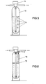
- sensors 74 are arranged at predetermined intervals from bottom to top in the pressure container 10, with which the position of the boundary layer between the exhausted mass and the still active mass in the exchanger mass is continuously determined.
- a regeneration operation is triggered, as much regenerant solution is or is provided as corresponds to the altitude of this boundary layer.
- a porous floating body 76 is placed on the exchanger mass.
- a measuring arrangement 78 is provided with which the height of the floating body 76 can be determined, which changes during the exhaustion of the exchanger mass, since this changes its volume during the loading with Ca and Mg ions.
Landscapes
- Chemical & Material Sciences (AREA)
- Organic Chemistry (AREA)
- Chemical Kinetics & Catalysis (AREA)
- Life Sciences & Earth Sciences (AREA)
- Hydrology & Water Resources (AREA)
- Engineering & Computer Science (AREA)
- Environmental & Geological Engineering (AREA)
- Water Supply & Treatment (AREA)
- Treatment Of Water By Ion Exchange (AREA)
Priority Applications (1)
| Application Number | Priority Date | Filing Date | Title |
|---|---|---|---|
| AT80107919T ATE1811T1 (de) | 1979-12-17 | 1980-12-15 | Verfahren zum zyklischen regenerieren von wasserenthaertungsanlagen und programmgesteuerte wasserenthaertungsanlage zur durchfuehrung des verfahrens. |
Applications Claiming Priority (2)
| Application Number | Priority Date | Filing Date | Title |
|---|---|---|---|
| DE2950728 | 1979-12-17 | ||
| DE2950728A DE2950728C2 (de) | 1979-12-17 | 1979-12-17 | Verfahren zum zyklischen Regenerieren von Wasserenthärtungsanlagen und programmgesteuerte Wasserenthärtungsanlage zur Durchführung des Verfahrens |
Publications (3)
| Publication Number | Publication Date |
|---|---|
| EP0031535A2 true EP0031535A2 (fr) | 1981-07-08 |
| EP0031535A3 EP0031535A3 (en) | 1981-09-23 |
| EP0031535B1 EP0031535B1 (fr) | 1982-11-17 |
Family
ID=6088714
Family Applications (1)
| Application Number | Title | Priority Date | Filing Date |
|---|---|---|---|
| EP80107919A Expired EP0031535B1 (fr) | 1979-12-17 | 1980-12-15 | Procédé pour la régénération cyclique de dispositifs pour l'adoucissement de l'eau et dispositif à commande à programme pour la mise en oeuvre du procédé |
Country Status (4)
| Country | Link |
|---|---|
| US (1) | US4379057A (fr) |
| EP (1) | EP0031535B1 (fr) |
| AT (1) | ATE1811T1 (fr) |
| DE (1) | DE2950728C2 (fr) |
Cited By (4)
| Publication number | Priority date | Publication date | Assignee | Title |
|---|---|---|---|---|
| GB2153698A (en) * | 1984-02-01 | 1985-08-29 | Eugene Foessel | Automatic regeneration of ion exchange cartridges |
| EP0447350A3 (en) * | 1990-03-15 | 1991-11-06 | Wm. R. Hague, Inc. | Comprehensive water treatment system |
| EP0571720A1 (fr) * | 1992-05-28 | 1993-12-01 | Judo Wasseraufbereitung GmbH | Installation de traitement d'eau |
| US5415767A (en) * | 1992-05-28 | 1995-05-16 | Judo Wasseraufbereitung Gmbh | Water treatment plant |
Families Citing this family (27)
| Publication number | Priority date | Publication date | Assignee | Title |
|---|---|---|---|---|
| FR2519964A1 (fr) * | 1982-01-15 | 1983-07-22 | Permo Sa | Appareil pour le traitement de liquides par resine echangeuse d'ions, plus particulierement appareil adoucisseur domestique d'eau |
| US4426294A (en) * | 1982-08-27 | 1984-01-17 | Autotrol Corporation | Microcomputer controlled demand/scheduled water softener |
| US4722797A (en) * | 1983-10-27 | 1988-02-02 | Ecodyne Corporation | Method for regeneration of a water softener |
| DE3441394A1 (de) * | 1984-11-13 | 1986-05-15 | Spiegl, Karl, 7031 Aidlingen | Verfahren und vorrichtung zur ionenaustauscherregenerierung |
| DE3506042A1 (de) * | 1985-02-21 | 1988-06-16 | Desch Kurt Michael | Steuerung fuer auch nur teilentladene wasseraufbereitungsanlagen mit mess- und oder pruefstellen fuer das wasser und oder die austauschermasse zur anpassung der regelmaessigen regenerationen an den jeweiligen erschoepfungsgrad der gesamt-austauschermasse |
| US4847598A (en) * | 1987-11-27 | 1989-07-11 | Aqua-Tronics, Inc. | Water treatment regeneration system incorporating alternating current excitation and paired operational amplifiers with asymmetrical feedback elements |
| DE3821036A1 (de) * | 1988-06-22 | 1989-12-28 | Kunz Gerhard K | Verfahren zum behandeln von ionenaustauschermassen, insbesondere zum regenerieren derselben nach enthaertung und entsalzung waessriger loesungen |
| DE3831811A1 (de) * | 1988-09-19 | 1990-03-22 | Ewald Meiser | Verfahren und vorrichtung zur steuerung der regenerierung von wasserenthaertungsanlagen |
| US5250187A (en) * | 1989-02-08 | 1993-10-05 | Autotrol Corporation | Resin bed for liquid treatment |
| US5348659A (en) * | 1992-03-18 | 1994-09-20 | Edr Acquisition Corp. | Countercurrent regeneration process |
| US5346623A (en) * | 1992-03-18 | 1994-09-13 | Edr Acquisition Corp. | Counter-current process for the rapid regeneration of ion exchange materials in an unrestrained bed |
| US5589058A (en) * | 1994-10-28 | 1996-12-31 | M. J. Bauer Company, Inc. | Apparatus for treatment of water |
| US5651880A (en) * | 1996-09-16 | 1997-07-29 | Johnson; Stanley O. | Water softener brine tank insert |
| US6036866A (en) * | 1997-03-10 | 2000-03-14 | Ecodyne Water Treatment, Inc. | Apparatus and method for fluid treatment units connected in parallel |
| DE19854651C1 (de) * | 1998-11-26 | 2000-05-04 | Ofs Online Fluid Sensoric Gmbh | Verfahren zum Betreiben einer Wasserenthärtungs-Ionentauscheranlage mit Regenerationseinheit durch in situ-Messung der Wasserresthärte mittels ionenselektiver Sensorik sowie Anordnung zur Durchführung eines derartigen Verfahrens |
| RU2139253C1 (ru) * | 1999-02-24 | 1999-10-10 | Государственный научный центр РФ Государственное предприятие Комплексный научно-исследовательский и конструкторско-технологический институт водоснабжения, канализации, гидротехнических сооружений и инженерной гидрогеологии "ВОДГЕО" | Способ ионообменной обработки воды |
| US6790362B2 (en) * | 2002-01-11 | 2004-09-14 | Culligan International Company | Efficiency mode for water softener |
| ITPN20030014A1 (it) * | 2003-02-26 | 2004-08-27 | Electrolux Ab | Macchina lavastoviglie automatica per collettivita' con |
| US20060120899A1 (en) * | 2004-12-07 | 2006-06-08 | Depuy Mitek, Inc. | Reusable pump cartridge |
| KR101165126B1 (ko) * | 2008-05-13 | 2012-07-12 | 웅진코웨이주식회사 | 연수기용 재생통 |
| WO2012053098A1 (fr) * | 2010-10-22 | 2012-04-26 | リンナイ株式会社 | Système d'alimentation en eau chaude |
| US20140013839A1 (en) * | 2011-06-08 | 2014-01-16 | Chandler Systems, Inc. | Water softener system and method |
| US8529768B2 (en) | 2011-06-08 | 2013-09-10 | Chandler Systems, Inc. | Water softener system and method |
| EP2657389A1 (fr) * | 2012-04-24 | 2013-10-30 | Electrolux Home Products Corporation N.V. | Machine à laver le linge |
| EP2657387A1 (fr) * | 2012-04-24 | 2013-10-30 | Electrolux Home Products Corporation N.V. | Machine à laver le linge comprenant un dispositif adoucisseur d'eau |
| US10612670B2 (en) | 2015-10-23 | 2020-04-07 | Culligan International Company | Control valve for fluid treatment apparatus |
| CN106802299A (zh) * | 2017-01-24 | 2017-06-06 | 厦门建霖工业有限公司 | 一种带进出水硬度监测功能的家用饮水机 |
Family Cites Families (11)
| Publication number | Priority date | Publication date | Assignee | Title |
|---|---|---|---|---|
| CH128483A (de) * | 1927-01-25 | 1928-11-01 | Josef Hellenbroich Wilhelm | Verfahren zum Regenerieren von basenaustauschender Filtermasse in Wasserenthärtungsapparaten. |
| DE1051248B (de) * | 1956-12-14 | 1959-02-26 | Preussische Elek Zitaets Ag | Ionenaustauschfilter und Verfahren zu dessen Betrieb |
| AT226607B (de) * | 1961-01-09 | 1963-03-25 | Rowenta Metallwarenfab Gmbh | Selbsttätige Filterregeneriervorrichtung |
| DE1442689C3 (de) * | 1963-11-29 | 1978-11-30 | Bayer Ag, 5090 Leverkusen | Verfahren zur Behandlung von Flüssigkeiten mit Ionenaustauschern |
| GB1228366A (fr) * | 1967-05-18 | 1971-04-15 | ||
| US3687289A (en) * | 1970-09-04 | 1972-08-29 | Ecodyne Corp | Water softener system |
| DE2300606C3 (de) * | 1973-01-08 | 1980-06-19 | Gebrueder Heyl Kg Gesellschaft Fuer Analysentechnik, 3200 Hildesheim | Schalteinrichtung zur Auslosung des Regenerationsbetriebes einer Wasserenthärtungsanlage |
| US4145279A (en) * | 1977-01-24 | 1979-03-20 | Pure Cycle Corporation | Water recycling system |
| US4104158A (en) * | 1977-03-18 | 1978-08-01 | Water Refining Company, Inc. | Volume and time of day control for water softener regeneration |
| US4275448A (en) * | 1978-11-24 | 1981-06-23 | Permo | Electronic means for controlling the regeneration of resins in a resin type ion exchange device |
| US4237538A (en) * | 1978-11-24 | 1980-12-02 | Permo S.A. | Electronic means for controlling the regeneration of resins in a resin type ion exchange device |
-
1979
- 1979-12-17 DE DE2950728A patent/DE2950728C2/de not_active Expired
-
1980
- 1980-12-05 US US06/213,728 patent/US4379057A/en not_active Expired - Lifetime
- 1980-12-15 EP EP80107919A patent/EP0031535B1/fr not_active Expired
- 1980-12-15 AT AT80107919T patent/ATE1811T1/de not_active IP Right Cessation
Cited By (4)
| Publication number | Priority date | Publication date | Assignee | Title |
|---|---|---|---|---|
| GB2153698A (en) * | 1984-02-01 | 1985-08-29 | Eugene Foessel | Automatic regeneration of ion exchange cartridges |
| EP0447350A3 (en) * | 1990-03-15 | 1991-11-06 | Wm. R. Hague, Inc. | Comprehensive water treatment system |
| EP0571720A1 (fr) * | 1992-05-28 | 1993-12-01 | Judo Wasseraufbereitung GmbH | Installation de traitement d'eau |
| US5415767A (en) * | 1992-05-28 | 1995-05-16 | Judo Wasseraufbereitung Gmbh | Water treatment plant |
Also Published As
| Publication number | Publication date |
|---|---|
| DE2950728A1 (de) | 1981-06-25 |
| EP0031535A3 (en) | 1981-09-23 |
| EP0031535B1 (fr) | 1982-11-17 |
| ATE1811T1 (de) | 1982-12-15 |
| DE2950728C2 (de) | 1982-12-02 |
| US4379057A (en) | 1983-04-05 |
Similar Documents
| Publication | Publication Date | Title |
|---|---|---|
| EP0031535B1 (fr) | Procédé pour la régénération cyclique de dispositifs pour l'adoucissement de l'eau et dispositif à commande à programme pour la mise en oeuvre du procédé | |
| DE3911028C2 (de) | Verfahren und Vorrichtung zum Zumessen von Waschmittel in eine Waschlösung | |
| CH615699A5 (fr) | ||
| DE2810820A1 (de) | Steuergeraet fuer wasserenthaerter und steuerungsverfahren | |
| DE2819231A1 (de) | Verfahren und vorrichtung zur behandlung von wasser | |
| EP0548317B1 (fr) | Procede et dispositif pour le melange de composants de boissons | |
| DE3913920C2 (fr) | ||
| DE2824302C2 (de) | Reinigungsvorrichtung für in einer Flüssigkeit angeordnete Meßelektroden | |
| DE2228657C3 (de) | Vorrichtung zum Behandeln von Wasser oder wäßrigen Lösungen | |
| CH670964A5 (fr) | ||
| DE1941391A1 (de) | Ionenaustauschverfahren | |
| DE102014119397B4 (de) | Spülmaschine mit einer Wasseraufbereitungsanlage | |
| DE19717009A1 (de) | Verfahren zum Befüllen eines Trinkwassertanks und Vorrichtung zur Trinkwasserversorgung | |
| DE60212261T2 (de) | Vorrichtung und Verfahren zum Kontrollieren der Wasserhärte einer Waschmaschine | |
| DE2834437A1 (de) | Enthaertungseinrichtung fuer haushaltgeraete, insbesondere geschirrspuel- und waschmaschinen | |
| DE1517483C3 (de) | Vorrichtung zum selbsttätigen Re generieren von Ionenaustauschern in Wasserenthartungsgeraten fur Wasch bzw Spulmaschinen, insbesondere Ge schirrspulmaschinen | |
| WO2005060817A1 (fr) | Lave-vaisselle comportant un systeme de detartrage | |
| DE4313292A1 (de) | Verfahren zum Zudosieren einer Chemikalie zu dem Wasserstrom eines Hochdruckreinigungsgerätes | |
| DE2033200A1 (de) | Wasserenthartevornchtung mit Ionenaus tauscher | |
| DE4239748C1 (de) | Retardationsanlage mit Druckluft-Membranpumpe und Hubzähleinrichtung | |
| AT226607B (de) | Selbsttätige Filterregeneriervorrichtung | |
| DE3044996C2 (fr) | ||
| DE3441394A1 (de) | Verfahren und vorrichtung zur ionenaustauscherregenerierung | |
| EP0635304B1 (fr) | Adoucisseur éclair | |
| DE3528617A1 (de) | Steuerung fuer auch nur teilbeladene wasseraufbereitungsanlagen mit mess- und/oder pruefstellen fuer das wasser und/oder die austauschermasse zur anpassung der regelmaessigen regenerationen an den jeweiligen erschoepfungsgrad der gesamt-austauschermasse |
Legal Events
| Date | Code | Title | Description |
|---|---|---|---|
| PUAI | Public reference made under article 153(3) epc to a published international application that has entered the european phase |
Free format text: ORIGINAL CODE: 0009012 |
|
| AK | Designated contracting states |
Designated state(s): AT BE CH FR GB IT NL |
|
| PUAL | Search report despatched |
Free format text: ORIGINAL CODE: 0009013 |
|
| AK | Designated contracting states |
Designated state(s): AT BE CH FR GB IT NL |
|
| 17P | Request for examination filed |
Effective date: 19810831 |
|
| GRAA | (expected) grant |
Free format text: ORIGINAL CODE: 0009210 |
|
| ITF | It: translation for a ep patent filed | ||
| AK | Designated contracting states |
Designated state(s): AT BE CH FR GB IT NL |
|
| REF | Corresponds to: |
Ref document number: 1811 Country of ref document: AT Date of ref document: 19821215 Kind code of ref document: T |
|
| ET | Fr: translation filed | ||
| ITTA | It: last paid annual fee | ||
| PGFP | Annual fee paid to national office [announced via postgrant information from national office to epo] |
Ref country code: GB Payment date: 19941228 Year of fee payment: 15 |
|
| PGFP | Annual fee paid to national office [announced via postgrant information from national office to epo] |
Ref country code: FR Payment date: 19941230 Year of fee payment: 15 Ref country code: AT Payment date: 19941230 Year of fee payment: 15 |
|
| PGFP | Annual fee paid to national office [announced via postgrant information from national office to epo] |
Ref country code: NL Payment date: 19941231 Year of fee payment: 15 |
|
| PGFP | Annual fee paid to national office [announced via postgrant information from national office to epo] |
Ref country code: BE Payment date: 19950106 Year of fee payment: 15 |
|
| PGFP | Annual fee paid to national office [announced via postgrant information from national office to epo] |
Ref country code: CH Payment date: 19950320 Year of fee payment: 15 |
|
| PG25 | Lapsed in a contracting state [announced via postgrant information from national office to epo] |
Ref country code: GB Effective date: 19951215 Ref country code: AT Effective date: 19951215 |
|
| PG25 | Lapsed in a contracting state [announced via postgrant information from national office to epo] |
Ref country code: LI Effective date: 19951231 Ref country code: CH Effective date: 19951231 Ref country code: BE Effective date: 19951231 |
|
| BERE | Be: lapsed |
Owner name: GEBR. HEYL K.G. G. FUR ANALYSENTECHNIK Effective date: 19951231 |
|
| PG25 | Lapsed in a contracting state [announced via postgrant information from national office to epo] |
Ref country code: NL Effective date: 19960701 |
|
| GBPC | Gb: european patent ceased through non-payment of renewal fee |
Effective date: 19951215 |
|
| REG | Reference to a national code |
Ref country code: CH Ref legal event code: PL |
|
| PG25 | Lapsed in a contracting state [announced via postgrant information from national office to epo] |
Ref country code: FR Effective date: 19960830 |
|
| NLV4 | Nl: lapsed or anulled due to non-payment of the annual fee |
Effective date: 19960701 |
|
| REG | Reference to a national code |
Ref country code: FR Ref legal event code: ST |
|
| PLBE | No opposition filed within time limit |
Free format text: ORIGINAL CODE: 0009261 |
|
| STAA | Information on the status of an ep patent application or granted ep patent |
Free format text: STATUS: NO OPPOSITION FILED WITHIN TIME LIMIT |