EP0031758A2 - Vacuum pump, particularly for diesel engines - Google Patents
Vacuum pump, particularly for diesel engines Download PDFInfo
- Publication number
- EP0031758A2 EP0031758A2 EP80401803A EP80401803A EP0031758A2 EP 0031758 A2 EP0031758 A2 EP 0031758A2 EP 80401803 A EP80401803 A EP 80401803A EP 80401803 A EP80401803 A EP 80401803A EP 0031758 A2 EP0031758 A2 EP 0031758A2
- Authority
- EP
- European Patent Office
- Prior art keywords
- chamber
- cavity
- inlet port
- pressure
- housing
- Prior art date
- Legal status (The legal status is an assumption and is not a legal conclusion. Google has not performed a legal analysis and makes no representation as to the accuracy of the status listed.)
- Granted
Links
Images

Classifications
-
- F—MECHANICAL ENGINEERING; LIGHTING; HEATING; WEAPONS; BLASTING
- F04—POSITIVE - DISPLACEMENT MACHINES FOR LIQUIDS; PUMPS FOR LIQUIDS OR ELASTIC FLUIDS
- F04C—ROTARY-PISTON, OR OSCILLATING-PISTON, POSITIVE-DISPLACEMENT MACHINES FOR LIQUIDS; ROTARY-PISTON, OR OSCILLATING-PISTON, POSITIVE-DISPLACEMENT PUMPS
- F04C28/00—Control of, monitoring of, or safety arrangements for, pumps or pumping installations specially adapted for elastic fluids
- F04C28/10—Control of, monitoring of, or safety arrangements for, pumps or pumping installations specially adapted for elastic fluids characterised by changing the positions of the inlet or outlet openings with respect to the working chamber
- F04C28/16—Control of, monitoring of, or safety arrangements for, pumps or pumping installations specially adapted for elastic fluids characterised by changing the positions of the inlet or outlet openings with respect to the working chamber using lift valves
-
- F—MECHANICAL ENGINEERING; LIGHTING; HEATING; WEAPONS; BLASTING
- F04—POSITIVE - DISPLACEMENT MACHINES FOR LIQUIDS; PUMPS FOR LIQUIDS OR ELASTIC FLUIDS
- F04C—ROTARY-PISTON, OR OSCILLATING-PISTON, POSITIVE-DISPLACEMENT MACHINES FOR LIQUIDS; ROTARY-PISTON, OR OSCILLATING-PISTON, POSITIVE-DISPLACEMENT PUMPS
- F04C28/00—Control of, monitoring of, or safety arrangements for, pumps or pumping installations specially adapted for elastic fluids
- F04C28/24—Control of, monitoring of, or safety arrangements for, pumps or pumping installations specially adapted for elastic fluids characterised by using valves controlling pressure or flow rate, e.g. discharge valves or unloading valves
- F04C28/26—Control of, monitoring of, or safety arrangements for, pumps or pumping installations specially adapted for elastic fluids characterised by using valves controlling pressure or flow rate, e.g. discharge valves or unloading valves using bypass channels
- F04C28/265—Control of, monitoring of, or safety arrangements for, pumps or pumping installations specially adapted for elastic fluids characterised by using valves controlling pressure or flow rate, e.g. discharge valves or unloading valves using bypass channels being obtained by displacing a lateral sealing face
-
- F—MECHANICAL ENGINEERING; LIGHTING; HEATING; WEAPONS; BLASTING
- F02—COMBUSTION ENGINES; HOT-GAS OR COMBUSTION-PRODUCT ENGINE PLANTS
- F02B—INTERNAL-COMBUSTION PISTON ENGINES; COMBUSTION ENGINES IN GENERAL
- F02B3/00—Engines characterised by air compression and subsequent fuel addition
- F02B3/06—Engines characterised by air compression and subsequent fuel addition with compression ignition
Definitions
- the present invention relates to a pump, and more specifically to a vacuum pump of the kind used in diesel engines for automotive vehicles, and it has for its main object to provide such a pump with an automatic relief device which reduces the work required to operate the pump as soon as the fluid pressure differential between its inlet and outlet ports reaches a predetermined value.
- an essential object of this invention to provide a pump of the kind referred to above with an automatic relief device capable of connecting the inlet port to the outlet port whenever a predetermined pressure differential is created therebetween, thus advantageously reducing the work required to operate such a continually running pump when the desired vacuum level is obtained.
- a pump of the kind having a housing which defines a working cavity therein, at least one movable member located in said cavity and sealingly separating an inlet port from an outlet port which both comnuni- cate with the cavity, and an input member adapted to move said movable member for introducing fluid through the inlet port into the cavity while removing fluid from the cavity through the outlet port, thanks to the fact that the housing includes a movable wall element which is responsive to a predetermined pressure differential between the inlet and outlet ports for moving from a first or closed position, in which it seals the working cavity and thus permits the pumpt to operate its normal way, to a second or open position in which it creates a by-pass chamber or passage connecting the inlet and outlet ports, thus substantially reducing the resistance to movement of the movable member within the working cavity as well as the work requirement of the input member
- the outlet port is usually connected to atmospheric pressure while the inlet port is communicated with a volume to be evacuated, and in such a case the pump according to this invention will further comprise a sensor member which measures the pressure at the inlet port and controls movement of the wall element of the housing whenever said pressure reaches a level corresponding to said predetermined pressure differential.
- the movable wall element of the housing comprises an axially-mov- - able plate which constitutes one of the end walls of the working cavity and which, in its first or closed position, is held by resilient means in engagement with said vanes.
- This movable plate is guided in a bore of the housing formed adjacent the working cavity and defines with said bore and said housing a control chamber which is communicated either with amospheric pressure or with inlet port pressure, said plate moving in this latter case to its second or open position under the action of the pressure reigning in the working cavity and thus creating a by-pass chamber on its side opposite to said control chamber.
- the communication of the control chamber with either atmospheric pressure or inlet port pressure is controlled through a control valve which itself is actuated by the sensor member when the pressure at the inlet port reaches a level corresponding to said predetermined pressure differential.
- the pump 10 shown in Figure 1 has a housing 12 with a cavity 14 therein.
- the cavity 14 has an inlet port 20, see Figure 2, which is connected to a reservoir 16 by a conduit 18, and an outlet port 22.
- a cylinder 24 is eccentrically positioned in cavity 14 by a shaft 26.
- the cylinder 24 has a series of radial slots 28, 30, 32, 34 located at substantially 90° from each other in which vanes 36, 38, 40 and 42 are retained. Vanes 36, 38, 40 and 42 cooperate with housing 12 to define a series of distinct chambers 44, 46, 48 and 50 in cavity 14. Because of the eccentric position of the cylinder 24 in cavity 14, the size of chambers 44, 46, 48 and 50 is continually varying whenever a rotary input is supplied to shaft 26 by a driving member.
- Shaft 26 has first and second races 52 and 54 in which balls 56 and 58 of bearing housing 60 are retained.
- Bearing housing 60 is retained in bore 62 of housing 12 by a snap ring fastener 64.
- An end cap 72 is attached to housing 12 by a series of bolts 74, 76.
- the end cap 72 has a bore 78 located therein with a control port 80 connected by conduit 82 to the supply reservoir 16.
- a cylindrical plate or wall 84 separates bore 78 into a control chamber 86 and a by-pass chamber 88, see figure 3.
- the cylindrical end plate or wall 84 has a projection 90 that is located in bore 92 in the end cap 72 in order to maintain surface 94 in a plane substantially perpendicular to bore 15 in housing 12 and bore 78 in end cap 72.
- a seal 96 is attached to the peripheral surface of the end plate or wall 84 to prevent fluid communication between the control chamber 86 and the by-pass chamber 88.
- a spring 98 located in the control chamber 86 acts on the back side of the end plate or wall 84 and urges face 94 into engagement with vanes 36, 38, 40 and 42 to prevent fluid communication between the inlet port 20'and the outlet port 22 under the operational conditions shown in Figure 1.
- a control valve 100 located in conduit 82 receives an operational. signal from a sensor member 102 located in the reservoir 16 to control the communication of fluid to control chamber 86.
- the sensor member 102 which is an evacuated bellows responding to an absolute pressure change such as differences in altitude, includes a corrugated cylindrical body 104 with a stem member 106 extending through an opening 108 therein.
- a spring 110 located in the cylindrical body 104 urges a head 112 on the stem member 106 against the closure cap 114 of the cylindrical body 104.
- the stem member 106 extends through a sealed opening 116 in a retainer and engages a control 122 on a relay switch 120.
- the relay switch 120 is connected by lead 124 to an indicator light 126 and a solenoid 128 in the control valve 100.
- the solenoid 128 has a housing 130 with a bore 132 located therein. Bore 132 has a first port 134 which is connected to control chamber 86 by conduit 82, a second port 136 which is connected to the surrounding environment and a third port 138 which is connected to reservoir 16 by conduit 140.
- a spool 142 has a first land 144 separated from a second land 146 by a stem 148.
- a plunger 150 located in coil 152 of the solenoid 128 is attached to the spool 142.
- a spring 154 acts on plunger 150 to move the lands 144 and 146 on spool 142 to a position shown in Figure 1 to provide unrestricted fluid communication between control chamber 86 and the surrounding environment by way of port 136, bore 132, port 134 and conduit 82.
- the above described pump device operates as follows :
- the pressure level in reservoir 16 is lowered. This lower pressure allows the corrugated cylinder 104 to expand. As cylinder 104 expands, spring 110 moves stem member 106 toward relay control 122. At some predetermined pressure level, the expansion of cylinder 104 is such that stem member 106 moves relay control 122 into a position to operate switch 120 and close an electrical circuit between power source 160 and ground 162. With this electrical circuit closed, light 126 operates and provides a visual indication that the reservoir pressure level is at a predetermined value and coil 152 in solenoid 128 is energized.
- the lowered fluid pressure of air or fluid in the reservoir 16 which is the same as the fluid pressure adjacent the inlet port 20, is communicated into the control chamber. Since the end plate or wall 84 has at least one-fourth of its surface area exposed to the fluid pressure (atmospheric pressure) at the outlet port 22, a pressure differential is created across the end plate or wall 84 with fluid at a lower pressure in the control chamber 86. This pressure differential acts on the end plate or wall 84 and overcomes spring 98 to move surface 94 on the end plate or wall 84 out of engagement with vanes 36, 38, 40 and 42 as shown in Figure 3 to establish by-pass chamber 88. With flow communication established between the inlet port and outlet port through the by-pass chamber 88, the resistance to movement of the vanes in cavity 14 is substantially eliminated and thus the work required to rotate shaft 26 correspondingly reduced.
- sensor member 102 again operates the switch 120 through which electrical energy is supplied to solenoid 128 to allow the fluid pressure in reservoir 16 to be communicated to control chamber 86 and re-establish a pressure differential across the wall or end plate 84.
- this pressure differential is sufficient to overcome spring 98, end plate or wall 84 moves to establish the by-pass chamber 88 through which the inlet port 20 is connected to the outlet port 22 to reduce the resistance to movement of the vanes 36, 38, 40 and 42 in the cavity 14 and correspondingly the work required to rotate shaft 26.
- the output of pump 10 is directly proportional to the vacuum or pressure level in reservoir 16 which is dependent on the operational need of the accessories.
- the housing 12' of the pump 10' shown in Figure 4 has a passage 200 that extends from the inlet port 20 to a point substantially adjacent an opening 202 in the side wall. Vanes 204, 206 and 208 which are located in slots 210, 212 and 214 engage bore 15' to define a series of chambers 216, 218 and 220 in cavity 14'.
- the size of opening 202 and the position of the vanes 204, 206 and 208 are selected so that the inlet and outlet ports 20 and 22 are substantially connected to the surrounding environment whenever a closure member 222 is removed from the opening 202.
- the closure member 222 has a lever arm 224 that is attached to a pivot pin 226 and a plunger 228 in a solenoid 230.
- a spring 232 acts on lever arm 224 to hold the plunger 228 out of the solenoid 230 and the closure member 222 against the housing 12' to seal bore 15' from the surrounding environment.
- a pump 10' installed in a vehicle and when the vehicle is operating, rotary input is continually supplied to shaft 26 from the crankshaft.
- Cylindrical body 24 rotates in housing 12' to move vanes 204, 206 and 208 past inlet port 20 to draw air from a reservoir and expelling the same to the surrounding environment or exhaust system through the outlet port 22.
- a pressure sensor closes an electrical circuit and allows current to flow to the coils in solenoid 23 ⁇ . With current flowing through the coils in solenoid 230, a magnetic field is created which moves plunger 228 to the center thereof by overcoming spring 232.
- lever arm 224 attached thereto pivots on pin 226 and moves closure member 222 out of engagement with housing 12' to allow fluid-communication from bore 15' to the surrounding environment through opening or relief port 202.
- Passage 200 and opening 202 provide a flow path through which substantially the entire bore 15' is connected to the surrounding environment at all times.
- the sensor interrupts the electrical current to the solenoid 230 and spring 232 moves plunger 228 and lever arm 224 to their inactive position as shown in Figure 4 to again allow fluid to be inoved from the inlet port 20 to the outlet port 22.
- the pump shown in Figure 5 has a bearing wall 300 that is located between housing 12" and an end cap member 302.
- End cap member 302 has a cavity 304 located therein that is separated into a sensing chamber 306 and an atmospheric chamber 308 by a diaphragm 310.
- a groove 312 in the bearing wall 300 communicates air from the surrounding environment into the atmospheric chamber 308.
- a poppet valve 312 has a sleeve 314 with a first end attached to the diaphragm 310 and a second end with a radial flange extending therefrom.
- the sleeve 314 extends through a central opening 316 in the bearing wall 300.
- a clearance between the central opening 316 and the peripheral surface of the sleeve 314 provides a flow path through which air is communicated from the atmospheric chamber 308 to the control chamber 86.
- a cylindrical member has a first diameter section 318 separated from a second diameter section 320 by a shoulder 322. The first diameter section 318 extends through the sleeve from the control chamber 86 into the sensing chamber 306.
- a retainer 324 attached to the end of the first diameter section 318 holds a spring 326 in the sensing chamber 306.
- the spring 326 acts on the cylindrical member to hold shoulder 322 against flange 315 and prevent communication between the atmospheric chamber 308 and the sensing chamber 306 by way of the control chamber 86 and sleeve 314.
- a snap action spring 328 is located in the sensing chamber 306 to hold the diaphragm 310 in a substantially fixed position during the evacuation of air from the reservoir 16.
- the pump of Figure 5 receives a rotary input from an operating engine causing the cylindrical body 24 to rotate in cavity 15. As vanes 36, 38, 40 and 42 rotate in cavity 15, air is evacuated from reservoir 16 by way of conduit 18.
- Sensing chamber 306 is connected to reservoir 16 by conduit 330 so that the fluid pressure level at the inlet port 20 and sensing chamber 306 is identical.
- a pressure differential develops across diaphragm 310 between air at atmospheric pressure in chamber 308 and the lower pressure in the sensing chamber 306.
- the diaphragm 310 is held stationary by the force of the snap action spring 328.
- the pressure differential across diaphragm 310 creates a force sufficient to overcome the force of the snap action spring.
- the snap action spring immediately collapses and diaphragm 310 moves the poppet valve 312 toward the sensing chamber 306.
- end 332 on the cylindrical member 318 engages housing 302 to establish a flow path between sensing chamber 306 and the control chamber 86.
- flange 315 engages seal 311 to prevent communication between atmospheric chamber 308 and control chamber 86.
- the pressure differential across diaphragm 310 is reduced.
- the snap action spring 328 immediately moves the diaphragm 310 toward the atmospheric chamber 308 whereby flange 315 is moved off of seal 311 to re-establish fluid communication between the atmospheric chamber 308 and control chamber 86 and allow spring 326 to move shoulder 322 against flange 315 to interrupt fluid communication between control chamber 86 and the sensing chamber 306.
- air enters the control chamber and eliminates the pressure differential force acting on the end plate or wall 84 and allows spring 98 to move the wall or end plate 84 into engagement with vanes 36, 38, 40 and 42 and eliminate flow between the inlet and outlet ports 20 and 22 through the by-pass chamber 88. Thereafter, air is evacuated from reservoir 16 by being drawn through the inlet port 20 and moved through the cavity by the vanes 36, 38, 40 and 42 before being expelled from outlet port 22.
- the pneumatically operated poppet valve 312 When the vacuum level in reservoir 16 again reaches a predetermined pressure level, the pneumatically operated poppet valve 312 is activated.and the fluid communication between the inlet and outlet ports 20 and 22 re-established to provide substantially unrestricted movement of the vanes 36, 38, 40 and 42 in the cavity 14.
- this invention contributes to the overall efficiency of the utilization of fuel in a vehicle, and, as such, should be considered as an important combination whenever vacuum operated accessories are used in vehicles equipped with diesel engines.
Landscapes
- Engineering & Computer Science (AREA)
- Mechanical Engineering (AREA)
- General Engineering & Computer Science (AREA)
- Physics & Mathematics (AREA)
- Fluid Mechanics (AREA)
- Applications Or Details Of Rotary Compressors (AREA)
- Rotary Pumps (AREA)
Abstract
Description
- The present invention relates to a pump, and more specifically to a vacuum pump of the kind used in diesel engines for automotive vehicles, and it has for its main object to provide such a pump with an automatic relief device which reduces the work required to operate the pump as soon as the fluid pressure differential between its inlet and outlet ports reaches a predetermined value.
- In known pumps, the only way of reducing the work required to rotate the vanes is to disengage the input member from the power source through some type of clutch arrangement. Unfortunately, when the power source is continually operating, noise can be created during the engagement of the clutch. In addition, the cost of such clutches can limit the application of the pump.
- With an increasing awareness of fuel efficiency it is estimated that up to 25% of the vehicles manufactured in 1985 will be powered by diesel engines. In order to provide continuity between the accessories used with internal combustion and diesel engines it will be necessary to provide a source of vacuum to operate many of the accessories. It has been determined that a continually operating pump can reduce the fuel efficiency of a diesel engine by about 5%. Since such a pump must be sized to meet peak demand of the accessories, during normal operation of the vehicle the demand for vacuum could be non-existent once the reserve capacity of vacuum is met. Thus, for optimum fuel efficiency, it is imperative that the input force driving the pump be reduced once the operational demand for vacuum is achieved.
- It is, therefore, an essential object of this invention to provide a pump of the kind referred to above with an automatic relief device capable of connecting the inlet port to the outlet port whenever a predetermined pressure differential is created therebetween, thus advantageously reducing the work required to operate such a continually running pump when the desired vacuum level is obtained.
- This object is achieved, according to the teaching of the present invention, and in a pump of the kind having a housing which defines a working cavity therein, at least one movable member located in said cavity and sealingly separating an inlet port from an outlet port which both comnuni- cate with the cavity, and an input member adapted to move said movable member for introducing fluid through the inlet port into the cavity while removing fluid from the cavity through the outlet port, thanks to the fact that the housing includes a movable wall element which is responsive to a predetermined pressure differential between the inlet and outlet ports for moving from a first or closed position, in which it seals the working cavity and thus permits the pumpt to operate its normal way, to a second or open position in which it creates a by-pass chamber or passage connecting the inlet and outlet ports, thus substantially reducing the resistance to movement of the movable member within the working cavity as well as the work requirement of the input member
- In the above mentioned application of such a pump, the outlet port is usually connected to atmospheric pressure while the inlet port is communicated with a volume to be evacuated, and in such a case the pump according to this invention will further comprise a sensor member which measures the pressure at the inlet port and controls movement of the wall element of the housing whenever said pressure reaches a level corresponding to said predetermined pressure differential.
- In a preferred embodiment of the invention, wherein the working cavity is of cylindrical shape and the movable member includes an eccentric cylindrical member carrying a plurality of radially movable vanes which slidably and sealingly engage the bore and the end walls of said cavity, the movable wall element of the housing comprises an axially-mov- - able plate which constitutes one of the end walls of the working cavity and which, in its first or closed position, is held by resilient means in engagement with said vanes. This movable plate is guided in a bore of the housing formed adjacent the working cavity and defines with said bore and said housing a control chamber which is communicated either with amospheric pressure or with inlet port pressure, said plate moving in this latter case to its second or open position under the action of the pressure reigning in the working cavity and thus creating a by-pass chamber on its side opposite to said control chamber. The communication of the control chamber with either atmospheric pressure or inlet port pressure is controlled through a control valve which itself is actuated by the sensor member when the pressure at the inlet port reaches a level corresponding to said predetermined pressure differential.
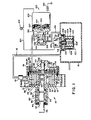
- These and other advantageous features of the invention will become more readily apparent from reading the following description of some preferred embodiments, given by way of examples only, and with reference to the accompanying drawings, in which :
- Figure 1 is a schematic illustration of a pump made according to the principles of this invention ;
- Figure 2 is a sectional view taken along lines 2-2 of Figure 1 ;
- Figure 3 is a sectional view of a portion of the pump in Figure 1 showing the end wall moved out of engagement with the vanes to provide flow communication between the inlet port and outlet port according to the principles of this invention ;
- Figure 4 is a sectional view of the pump showing a relief port through which the inlet and outlet ports are connected to the surrounding environment to reduce the work required to rotate the vanes when a predetermined pressure differential develops between the inlet and outlet ports; and
- Figure 5 is a sectional view of a portion of the pump of Figure 1 showing a pneumatic sensor associated with the end plate to control the movement thereof during the development of a pressure differential between the inlet port and the outlet port.
- The
pump 10 shown in Figure 1 has ahousing 12 with acavity 14 therein. Thecavity 14 has aninlet port 20, see Figure 2, which is connected to areservoir 16 by aconduit 18, and anoutlet port 22. Acylinder 24 is eccentrically positioned incavity 14 by ashaft 26. Thecylinder 24 has a series ofradial slots housing 12 to define a series ofdistinct chambers cavity 14. Because of the eccentric position of thecylinder 24 incavity 14, the size ofchambers shaft 26 by a driving member. - Shaft 26 has first and
second races balls housing 60 are retained.Bearing housing 60 is retained inbore 62 ofhousing 12 by asnap ring fastener 64. Akey 66 located betweenslot 68 on the end ofshaft 26 incavity 14 andslot 70 incylindrical member 24 assures that each revolution ofshaft 26 is transmitted intocylindrical member 24. - An
end cap 72 is attached tohousing 12 by a series ofbolts end cap 72 has abore 78 located therein with acontrol port 80 connected byconduit 82 to thesupply reservoir 16. A cylindrical plate orwall 84 separates bore 78 into acontrol chamber 86 and a by-pass chamber 88, see figure 3. The cylindrical end plate orwall 84 has aprojection 90 that is located inbore 92 in theend cap 72 in order to maintainsurface 94 in a plane substantially perpendicular to bore 15 inhousing 12 and bore 78 inend cap 72. Aseal 96 is attached to the peripheral surface of the end plate orwall 84 to prevent fluid communication between thecontrol chamber 86 and the by-pass chamber 88. Aspring 98 located in thecontrol chamber 86 acts on the back side of the end plate orwall 84 andurges face 94 into engagement withvanes outlet port 22 under the operational conditions shown in Figure 1. - A
control valve 100 located inconduit 82 receives an operational. signal from asensor member 102 located in thereservoir 16 to control the communication of fluid tocontrol chamber 86. - The
sensor member 102, which is an evacuated bellows responding to an absolute pressure change such as differences in altitude, includes a corrugatedcylindrical body 104 with astem member 106 extending through anopening 108 therein. Aspring 110 located in thecylindrical body 104 urges ahead 112 on thestem member 106 against theclosure cap 114 of thecylindrical body 104. Thestem member 106 extends through a sealedopening 116 in a retainer and engages a control 122 on arelay switch 120. - The
relay switch 120 is connected bylead 124 to anindicator light 126 and asolenoid 128 in thecontrol valve 100. - The
solenoid 128 has ahousing 130 with abore 132 located therein. Bore 132 has afirst port 134 which is connected tocontrol chamber 86 byconduit 82, asecond port 136 which is connected to the surrounding environment and athird port 138 which is connected toreservoir 16 byconduit 140. Aspool 142 has afirst land 144 separated from asecond land 146 by astem 148. Aplunger 150 located incoil 152 of thesolenoid 128 is attached to thespool 142. Aspring 154 acts onplunger 150 to move thelands spool 142 to a position shown in Figure 1 to provide unrestricted fluid communication betweencontrol chamber 86 and the surrounding environment by way ofport 136,bore 132,port 134 andconduit 82. - The above described pump device operates as follows :
- It is intended that when a vehicle equipped with
pump 10 is operating a continual rotary input is applied toshaft 26 through some type of connection with the crankshaft. Whenshaft 26 rotates,cylindrical member 24 rotates to movevanes cavity 14. The centrifugal force generated by the rotation ofcylindrical body 24 causes the ends ofvanes surface 15 and thereby separatechambers - As a vane moves past
inlet port 20, air or fluid is drawnpast check valve 19 and into the chamber until the next vane moves past the inlet port. The air or fluid drawn into the chamber is transmitted through thecavity 14 and expelled through theoutlet port 22 into the surrounding environment or into the intake manifold or air cleaner of the vehicle. The dumping of air or fluid into the intake manifold or air cleaner is preferred since it is a silent way of disposing of the air. - As the
vanes inlet port 20 to theoutlet port 22 throughcavity 14, the pressure level inreservoir 16 is lowered. This lower pressure allows thecorrugated cylinder 104 to expand. Ascylinder 104 expands,spring 110 moves stemmember 106 toward relay control 122. At some predetermined pressure level, the expansion ofcylinder 104 is such thatstem member 106 moves relay control 122 into a position to operateswitch 120 and close an electrical circuit betweenpower source 160 andground 162. With this electrical circuit closed,light 126 operates and provides a visual indication that the reservoir pressure level is at a predetermined value andcoil 152 insolenoid 128 is energized. Withcoil 152 energized, the magnetic field created thereinmoves plunger 150 to the center of the magnetic field. Asplunger 150 moves,spool 142 also moves to interrupt communication from the surrounding environment throughport 136 and initiate communication betweenreservoir 16 andcontrol chamber 86 by way ofconduit 140,port 138,bore 132,port 134 andconduit 82. - Thus, the lowered fluid pressure of air or fluid in the
reservoir 16, which is the same as the fluid pressure adjacent theinlet port 20, is communicated into the control chamber. Since the end plate orwall 84 has at least one-fourth of its surface area exposed to the fluid pressure (atmospheric pressure) at theoutlet port 22, a pressure differential is created across the end plate orwall 84 with fluid at a lower pressure in thecontrol chamber 86. This pressure differential acts on the end plate orwall 84 and overcomesspring 98 to movesurface 94 on the end plate orwall 84 out of engagement withvanes pass chamber 88. With flow communication established between the inlet port and outlet port through the by-pass chamber 88, the resistance to movement of the vanes incavity 14 is substantially eliminated and thus the work required to rotateshaft 26 correspondingly reduced. - As the fluid pressure in
reservoir 16 rises due to depletion thereof by vacuum operated accessories, this same pressure rise is communicated to thecorrugated cylinder 104 throughpassages corrugated cylinder 104 and causes a contraction of the same since the fluid pressure in evacuated chamber is lower than that in thereservoir 16. When corrugated,cylinder 104 has contracted a predetermined distance corresponding to a rise in the pressure level in the reservoir,stem member 106 is moved . away from relay control 122. After a predetermined amount of movement, relay control 122 opens switch 120 to interrupt electrical current flow inlead 124. With swith 120 opened, the magnetic field incoil 152 decays andspring 154 movesplunger 150 andspool 142 to the position shown in Figure 1. Thereafter, air from the surrounding environment is communicated to thecontrol chamber 86 to eliminate the pressure differential across end plate orwall 84. With the pressure differential eliminated,spring 98 moves the end plate orwall 84 such thatsurface 94 engagesvanes inlet port 20 andoutlet port 22 through the by-pass chamber 88. Thereafter, thevanes reservoir 16 to reduce the fluid pressure therein in order to meet a vacuum demand of the accessories. When thepump 10 has again reduced the fluid pressure in the reservoir to a preselected level,sensor member 102 again operates theswitch 120 through which electrical energy is supplied to solenoid 128 to allow the fluid pressure inreservoir 16 to be communicated to controlchamber 86 and re-establish a pressure differential across the wall orend plate 84. When this pressure differential is sufficient to overcomespring 98, end plate orwall 84 moves to establish the by-pass chamber 88 through which theinlet port 20 is connected to theoutlet port 22 to reduce the resistance to movement of thevanes cavity 14 and correspondingly the work required to rotateshaft 26. - Thus, the output of
pump 10 is directly proportional to the vacuum or pressure level inreservoir 16 which is dependent on the operational need of the accessories. - In the embodiments of the invention shown in Figures 4 and 5, elements of the pump that are identical tothose.in Figure 1 are identified by the same reference numbers.
- The
housing 12' of the pump 10' shown in Figure 4 has apassage 200 that extends from theinlet port 20 to a point substantially adjacent anopening 202 in the side wall.Vanes slots chambers opening 202 and the position of thevanes outlet ports closure member 222 is removed from theopening 202. - The
closure member 222 has alever arm 224 that is attached to apivot pin 226 and aplunger 228 in asolenoid 230. Aspring 232 acts onlever arm 224 to hold theplunger 228 out of thesolenoid 230 and theclosure member 222 against thehousing 12' to seal bore 15' from the surrounding environment. - With a pump 10' installed in a vehicle and when the vehicle is operating, rotary input is continually supplied to
shaft 26 from the crankshaft.Cylindrical body 24 rotates inhousing 12' to movevanes past inlet port 20 to draw air from a reservoir and expelling the same to the surrounding environment or exhaust system through theoutlet port 22. Whenever the pressure level in the reservoir reaches a level sufficient to operate the accessories while providing sufficient storage for energizing operation, a pressure sensor closes an electrical circuit and allows current to flow to the coils in solenoid 23θ. With current flowing through the coils insolenoid 230, a magnetic field is created which movesplunger 228 to the center thereof by overcomingspring 232. With movement of theplunger 228,lever arm 224 attached thereto pivots onpin 226 and movesclosure member 222 out of engagement withhousing 12' to allow fluid-communication from bore 15' to the surrounding environment through opening orrelief port 202.Passage 200 andopening 202 provide a flow path through which substantially the entire bore 15' is connected to the surrounding environment at all times. Thus, the resistance to movement ofvanes shaft 26 substantially eliminated once the pressure level in the reservoir is achieved. Once the pressure level in the reservoir raises, the sensor interrupts the electrical current to thesolenoid 230 andspring 232 movesplunger 228 andlever arm 224 to their inactive position as shown in Figure 4 to again allow fluid to be inoved from theinlet port 20 to theoutlet port 22. - The pump shown in Figure 5 has a
bearing wall 300 that is located betweenhousing 12" and anend cap member 302.End cap member 302 has acavity 304 located therein that is separated into asensing chamber 306 and anatmospheric chamber 308 by adiaphragm 310. Agroove 312 in thebearing wall 300 communicates air from the surrounding environment into theatmospheric chamber 308. , - A
poppet valve 312 has asleeve 314 with a first end attached to thediaphragm 310 and a second end with a radial flange extending therefrom. Thesleeve 314 extends through acentral opening 316 in thebearing wall 300. A clearance between thecentral opening 316 and the peripheral surface of thesleeve 314 provides a flow path through which air is communicated from theatmospheric chamber 308 to thecontrol chamber 86. A cylindrical member has afirst diameter section 318 separated from asecond diameter section 320 by ashoulder 322. Thefirst diameter section 318 extends through the sleeve from thecontrol chamber 86 into thesensing chamber 306. Aretainer 324 attached to the end of thefirst diameter section 318 holds aspring 326 in thesensing chamber 306. Thespring 326 acts on the cylindrical member to holdshoulder 322 againstflange 315 and prevent communication between theatmospheric chamber 308 and thesensing chamber 306 by way of thecontrol chamber 86 andsleeve 314. - A
snap action spring 328 is located in thesensing chamber 306 to hold thediaphragm 310 in a substantially fixed position during the evacuation of air from thereservoir 16. - As with the
pump 10 shown in Figure 1, the pump of Figure 5 receives a rotary input from an operating engine causing thecylindrical body 24 to rotate incavity 15. Asvanes cavity 15, air is evacuated fromreservoir 16 by way ofconduit 18. -
Sensing chamber 306 is connected toreservoir 16 byconduit 330 so that the fluid pressure level at theinlet port 20 andsensing chamber 306 is identical. As air is evacuated from thereservoir 16, a pressure differential develops acrossdiaphragm 310 between air at atmospheric pressure inchamber 308 and the lower pressure in thesensing chamber 306. However, thediaphragm 310 is held stationary by the force of thesnap action spring 328. At some predetermined pressure level inreservoir 16, the pressure differential acrossdiaphragm 310 creates a force sufficient to overcome the force of the snap action spring. When this pressure differential is reached, the snap action spring immediately collapses anddiaphragm 310 moves thepoppet valve 312 toward thesensing chamber 306. After thediaphragm 310 has moved a predetermined distance, end 332 on thecylindrical member 318 engageshousing 302 to establish a flow path betweensensing chamber 306 and thecontrol chamber 86. Thereafter,flange 315 engages seal 311 to prevent communication betweenatmospheric chamber 308 andcontrol chamber 86. With flow communication established betweensensing chamber 306 andcontrol chamber 86, the fluid pressure level at theinlet port 20 and in thereservoir 16 is present in thecontrol chamber 86. Since at least a portion ofwall 84 is exposed to the pressure of the surrounding environment, a pressure differential develops acrosswall 84. When the force from this pressure differential is suffi- . cient to overcomespring 98,wall 84 moves to establish a by-pass chamber 88 in thehousing 12" between theinlet port 20 andoutlet port 22.' Spring 334 in one-way check valve 19 holds adisc 336 to sealconduit 18 from the by-pass chamber 88 and prevent the dilution of the vacuum level inreservoir 16 with air from theoutlet port 22. With theinlet port 20 connected to theoutlet port 22, the resistance to movement ofvanes cavity 14 is reduced and the work required to rotateshaft 26 substantially eliminated. - As the pressure level in
reservoir 16 rises from use of the vacuum by accessories, the pressure differential acrossdiaphragm 310 is reduced. At some pressure level, thesnap action spring 328 immediately moves thediaphragm 310 toward theatmospheric chamber 308 wherebyflange 315 is moved off of seal 311 to re-establish fluid communication between theatmospheric chamber 308 andcontrol chamber 86 and allowspring 326 to moveshoulder 322 againstflange 315 to interrupt fluid communication betweencontrol chamber 86 and thesensing chamber 306. With fluid communication established between thecontrol chamber 86 andatmospheric chamber 308, air enters the control chamber and eliminates the pressure differential force acting on the end plate orwall 84 and allowsspring 98 to move the wall orend plate 84 into engagement withvanes outlet ports pass chamber 88. Thereafter, air is evacuated fromreservoir 16 by being drawn through theinlet port 20 and moved through the cavity by thevanes outlet port 22. When the vacuum level inreservoir 16 again reaches a predetermined pressure level, the pneumatically operatedpoppet valve 312 is activated.and the fluid communication between the inlet andoutlet ports vanes cavity 14. - From experimental data accumulated with the pump devices described hereabove it is estimated that the operation work requirement of an engine has been reduced from about 5% to 2% which could result in an increase in fuel kilometrage up to 1,7 km per liter. Thus, this invention contributes to the overall efficiency of the utilization of fuel in a vehicle, and, as such, should be considered as an important combination whenever vacuum operated accessories are used in vehicles equipped with diesel engines.
Claims (10)
Applications Claiming Priority (2)
| Application Number | Priority Date | Filing Date | Title |
|---|---|---|---|
| US107125 | 1979-12-26 | ||
| US06/107,125 US4336004A (en) | 1979-12-26 | 1979-12-26 | Movable end plate for a vacuum pump |
Publications (3)
| Publication Number | Publication Date |
|---|---|
| EP0031758A2 true EP0031758A2 (en) | 1981-07-08 |
| EP0031758A3 EP0031758A3 (en) | 1981-07-15 |
| EP0031758B1 EP0031758B1 (en) | 1984-03-14 |
Family
ID=22314990
Family Applications (1)
| Application Number | Title | Priority Date | Filing Date |
|---|---|---|---|
| EP80401803A Expired EP0031758B1 (en) | 1979-12-26 | 1980-12-16 | Vacuum pump, particularly for diesel engines |
Country Status (5)
| Country | Link |
|---|---|
| US (1) | US4336004A (en) |
| EP (1) | EP0031758B1 (en) |
| JP (1) | JPS56115823A (en) |
| CA (1) | CA1166613A (en) |
| DE (1) | DE3067057D1 (en) |
Cited By (7)
| Publication number | Priority date | Publication date | Assignee | Title |
|---|---|---|---|---|
| FR2517380A1 (en) * | 1981-11-30 | 1983-06-03 | Rivapompe Sa | Sliding vane vacuum pump - has single eccentric rotor driven from vehicle gear-box shaft with oil feed |
| EP0146612A4 (en) * | 1983-06-06 | 1987-09-02 | Edward Charles Mendler Iii | Rotary machine. |
| GB2225058A (en) * | 1988-10-18 | 1990-05-23 | Baker Hughes Inc | Rotary pump having an adjustable wearplate |
| EP0645540A1 (en) * | 1993-09-27 | 1995-03-29 | Zexel Usa Corporation | Variable capacity vane compressor with axial pressure device |
| EP1715186A3 (en) * | 2005-04-21 | 2007-10-24 | ixetic Hückeswagen GmbH | pump |
| EP2698541A2 (en) * | 2012-08-14 | 2014-02-19 | Schwäbische Hüttenwerke Automotive GmbH | Rotary pump with adjustable delivery volume, especially for adjusting a coolant pump |
| EP2754896A1 (en) * | 2013-01-14 | 2014-07-16 | Schwäbische Hüttenwerke Automotive GmbH | Gas pump with pressure relief for reducing start-up torque |
Families Citing this family (7)
| Publication number | Priority date | Publication date | Assignee | Title |
|---|---|---|---|---|
| BR8200378A (en) * | 1981-01-27 | 1982-11-23 | Nippon Denso Co | ROTARY DISCHARGE COMPRESSOR VARIABLE |
| US4834631A (en) * | 1988-04-04 | 1989-05-30 | Carrier Corporation | Separator and biasing plate |
| DE19818141C2 (en) * | 1998-04-23 | 2003-04-30 | Trw Fahrwerksyst Gmbh & Co | Method for limiting the pressure provided by a hydraulic pump and hydraulic pump for carrying out the method |
| DE19924645A1 (en) * | 1999-05-28 | 2000-11-30 | Lmf Leobersdorfer Maschinenfab | Rotary vane compressor or vacuum pump |
| DE19942687C2 (en) * | 1999-09-07 | 2002-06-20 | Leobersdorfer Maschf | Rotary vane engine |
| SE530959C2 (en) * | 2006-05-29 | 2008-11-04 | Climatewell Ab Publ | Chemical heat pump with hybrid substance |
| ITTO20080911A1 (en) * | 2008-12-09 | 2010-06-10 | Vhit S P A Unipersonale | VACUUM PUMP WITH MOBILE LID |
Family Cites Families (15)
| Publication number | Priority date | Publication date | Assignee | Title |
|---|---|---|---|---|
| GB336295A (en) * | 1929-07-12 | 1930-10-13 | George Edward Thomas Eyston | Improvements in and relating to the control of superchargers, blowers or compressors |
| DE767417C (en) * | 1941-01-15 | 1952-08-07 | Hans Schmitt Dipl Ing | Device for setting different pressures with different fillings of vane or rotary piston machines working as compressors |
| US2492075A (en) * | 1945-10-30 | 1949-12-20 | Kinney Mfg Company | Vacuum pump |
| US2577559A (en) * | 1948-07-01 | 1951-12-04 | Jacuzzi Bros Inc | Submersible pump assembly |
| GB722667A (en) * | 1952-02-01 | 1955-01-26 | Zenith Carburateur Soc Du | Improvements in or relating to gear pumps and applications thereof |
| GB750673A (en) * | 1953-06-26 | 1956-06-20 | Zenith Carburateur Soc Du | Improvements in or relating to gear pumps and applications thereof |
| US2845868A (en) * | 1955-01-12 | 1958-08-05 | Borg Warner | Gear pump |
| US3182596A (en) * | 1963-05-31 | 1965-05-11 | Borg Warner | Hydraulic systems and pumps |
| GB1319211A (en) * | 1970-10-08 | 1973-06-06 | Gen Motors Corp | Trochoidal-type rotary positive-displacement compressors |
| US3806283A (en) * | 1973-01-04 | 1974-04-23 | Int Standard Electric Corp | Pump by-pass |
| US4014630A (en) * | 1974-06-03 | 1977-03-29 | Trw Inc. | Power steering pump |
| US3930759A (en) * | 1974-06-03 | 1976-01-06 | Trw Inc. | Integral housing pump with servo controlled cheek plate |
| US4060343A (en) * | 1976-02-19 | 1977-11-29 | Borg-Warner Corporation | Capacity control for rotary compressor |
| US4073605A (en) * | 1976-09-15 | 1978-02-14 | Crepaco, Inc. | Rotary pump construction with cleaning feature |
| ZA782350B (en) * | 1977-05-26 | 1979-04-25 | Stainless Steel Pumps Ltd | Lobe-rotor pump |
-
1979
- 1979-12-26 US US06/107,125 patent/US4336004A/en not_active Expired - Lifetime
-
1980
- 1980-11-13 CA CA000364565A patent/CA1166613A/en not_active Expired
- 1980-12-16 DE DE8080401803T patent/DE3067057D1/en not_active Expired
- 1980-12-16 EP EP80401803A patent/EP0031758B1/en not_active Expired
- 1980-12-24 JP JP18367880A patent/JPS56115823A/en active Pending
Cited By (9)
| Publication number | Priority date | Publication date | Assignee | Title |
|---|---|---|---|---|
| FR2517380A1 (en) * | 1981-11-30 | 1983-06-03 | Rivapompe Sa | Sliding vane vacuum pump - has single eccentric rotor driven from vehicle gear-box shaft with oil feed |
| EP0146612A4 (en) * | 1983-06-06 | 1987-09-02 | Edward Charles Mendler Iii | Rotary machine. |
| GB2225058A (en) * | 1988-10-18 | 1990-05-23 | Baker Hughes Inc | Rotary pump having an adjustable wearplate |
| GB2225058B (en) * | 1988-10-18 | 1993-02-24 | Baker Hughes Inc | Rotary pump wearplates |
| EP0645540A1 (en) * | 1993-09-27 | 1995-03-29 | Zexel Usa Corporation | Variable capacity vane compressor with axial pressure device |
| EP1715186A3 (en) * | 2005-04-21 | 2007-10-24 | ixetic Hückeswagen GmbH | pump |
| EP2698541A2 (en) * | 2012-08-14 | 2014-02-19 | Schwäbische Hüttenwerke Automotive GmbH | Rotary pump with adjustable delivery volume, especially for adjusting a coolant pump |
| EP2754896A1 (en) * | 2013-01-14 | 2014-07-16 | Schwäbische Hüttenwerke Automotive GmbH | Gas pump with pressure relief for reducing start-up torque |
| EP3421802A1 (en) * | 2013-01-14 | 2019-01-02 | Schwäbische Hüttenwerke Automotive GmbH | Gas pump with pressure relief for reducing start-up torque |
Also Published As
| Publication number | Publication date |
|---|---|
| DE3067057D1 (en) | 1984-04-19 |
| CA1166613A (en) | 1984-05-01 |
| US4336004A (en) | 1982-06-22 |
| JPS56115823A (en) | 1981-09-11 |
| EP0031758A3 (en) | 1981-07-15 |
| EP0031758B1 (en) | 1984-03-14 |
Similar Documents
| Publication | Publication Date | Title |
|---|---|---|
| US4336004A (en) | Movable end plate for a vacuum pump | |
| US5248123A (en) | Pilot operated hydraulic valve actuator | |
| US4711224A (en) | Check valve in auxiliary vacuum system | |
| EP0357246A2 (en) | Shaft seal arrangement of turbocharger | |
| EP0231648B1 (en) | Variable capacity vane compressor | |
| US3576241A (en) | Hydraulic control devices of transmission mechanisms | |
| US3753426A (en) | Balanced pressure fuel valve | |
| US3102382A (en) | Turbocharger waste gate system | |
| US4557240A (en) | Injection timing control device for distributor-type fuel injection pumps | |
| US2691388A (en) | Pressure regulating valve for pumps | |
| EP2935893B1 (en) | A vacuum pump having a disconnectable drive coupling | |
| US4309149A (en) | Vacuum pump switch | |
| EP0608324B1 (en) | A check valve | |
| US3934413A (en) | Air flow control unit for engine secondary air supply | |
| US4398871A (en) | Movable end plate for a vacuum pump | |
| US4016716A (en) | Gas turbine engine dump valve | |
| EP0080801B1 (en) | Dump delay valve | |
| US4291612A (en) | Power brake system differential air pressure control valve assembly | |
| US4136656A (en) | Load control device for turbo-suspercharged diesel engines | |
| US3768366A (en) | Selective pressure differential reinforcing means | |
| EP0326376A1 (en) | Hydraulic pump unloader means | |
| US4064894A (en) | Vacuum reducer valve | |
| US3412647A (en) | Rotary piston type fluid motor | |
| GB2196701A (en) | Fuel injection pump | |
| CA1219573A (en) | Thermally responsive valve |
Legal Events
| Date | Code | Title | Description |
|---|---|---|---|
| PUAI | Public reference made under article 153(3) epc to a published international application that has entered the european phase |
Free format text: ORIGINAL CODE: 0009012 |
|
| PUAL | Search report despatched |
Free format text: ORIGINAL CODE: 0009013 |
|
| 17P | Request for examination filed |
Effective date: 19801223 |
|
| AK | Designated contracting states |
Designated state(s): DE FR GB |
|
| AK | Designated contracting states |
Designated state(s): DE FR GB |
|
| GRAA | (expected) grant |
Free format text: ORIGINAL CODE: 0009210 |
|
| AK | Designated contracting states |
Designated state(s): DE FR GB |
|
| PG25 | Lapsed in a contracting state [announced via postgrant information from national office to epo] |
Ref country code: FR Free format text: THE PATENT HAS BEEN ANNULLED BY A DECISION OF A NATIONAL AUTHORITY Effective date: 19840314 |
|
| REF | Corresponds to: |
Ref document number: 3067057 Country of ref document: DE Date of ref document: 19840419 |
|
| EN | Fr: translation not filed | ||
| PLBE | No opposition filed within time limit |
Free format text: ORIGINAL CODE: 0009261 |
|
| STAA | Information on the status of an ep patent application or granted ep patent |
Free format text: STATUS: NO OPPOSITION FILED WITHIN TIME LIMIT |
|
| 26N | No opposition filed | ||
| GBPC | Gb: european patent ceased through non-payment of renewal fee | ||
| PG25 | Lapsed in a contracting state [announced via postgrant information from national office to epo] |
Ref country code: DE Effective date: 19850903 |
|
| PG25 | Lapsed in a contracting state [announced via postgrant information from national office to epo] |
Ref country code: GB Effective date: 19881118 |