EP0033606A1 - Procédés et décodeurs pour le décodage de signaux de télévision PAL composites - Google Patents
Procédés et décodeurs pour le décodage de signaux de télévision PAL composites Download PDFInfo
- Publication number
- EP0033606A1 EP0033606A1 EP81300244A EP81300244A EP0033606A1 EP 0033606 A1 EP0033606 A1 EP 0033606A1 EP 81300244 A EP81300244 A EP 81300244A EP 81300244 A EP81300244 A EP 81300244A EP 0033606 A1 EP0033606 A1 EP 0033606A1
- Authority
- EP
- European Patent Office
- Prior art keywords
- signal
- quarter
- delayed
- minus
- delayed signal
- Prior art date
- Legal status (The legal status is an assumption and is not a legal conclusion. Google has not performed a legal analysis and makes no representation as to the accuracy of the status listed.)
- Granted
Links
Images

Classifications
-
- H—ELECTRICITY
- H04—ELECTRIC COMMUNICATION TECHNIQUE
- H04N—PICTORIAL COMMUNICATION, e.g. TELEVISION
- H04N11/00—Colour television systems
- H04N11/06—Transmission systems characterised by the manner in which the individual colour picture signal components are combined
- H04N11/12—Transmission systems characterised by the manner in which the individual colour picture signal components are combined using simultaneous signals only
- H04N11/14—Transmission systems characterised by the manner in which the individual colour picture signal components are combined using simultaneous signals only in which one signal, modulated in phase and amplitude, conveys colour information and a second signal conveys brightness information, e.g. NTSC-system
- H04N11/16—Transmission systems characterised by the manner in which the individual colour picture signal components are combined using simultaneous signals only in which one signal, modulated in phase and amplitude, conveys colour information and a second signal conveys brightness information, e.g. NTSC-system the chrominance signal alternating in phase, e.g. PAL-system
- H04N11/165—Decoding means therefor
Definitions
- This invention relates to decoding composite PAL television signals.
- the standard method of decoding a composite PAL television signal used in domestic PAL colour television receivers makes use of a decoder including a delay device whereby information is derived from two successive horizontal scan lines.
- One reason for the defect is the failure properly to separate the chrominance components U and V from the incoming signal.
- a method of decoding a composite PAL television signal comprising the steps of:
- a composite PAL television signal decoder comprising:
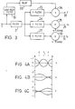
- Figures 1A to 1C respectively represent the filter coefficients required for decoding the luminance component Y and chrominance components U and V in an incoming PAL colour television signal.
- the bottom line represents the horizontal scan line currently being received, so it will be appreciated that the three scan lines can be made available by delaying two successive scan lines until the next successive scan line is received.
- the vertical lines represent time in the horizontal scan direction, the centre vertical line being a reference time referred to the bottom horizontal line.
- the vertical lines to the left and right represent time one quarter of a period of the colour sub-carrier signal behind and ahead of the reference time respectively. In terms of time, therefore, the. distance between the horizontal lines is 64 microseconds and the distance between the vertical lines is 56 nanoseconds.
- the points A, B, C and D represent the signals at various time points on the characteristics. If A is taken to be the signal at a reference time, then D is the signal two horizontal scan lines before, and B and C are the signals one horizontal scan line plus and minus respectively one quarter of the period of the colour sub-carrier signal before.
- the luminance component Y and the chrominance components U and V can be derived as follows:
- the reason why the components Y, U and V can be obtained by the above equations can be explained as follows.
- the phases of the chrominance components U and V in the third line are inverted compared with those in the first line, because the PAL colour sub-carrier signal has a quarter- line-offset.
- the chrominance components U and V are cancelled and only the luminance component Y remains, as indicated by the first equation above.
- the chrominance component U the chrominance components U of the signals B and D have the same relative phase, while the chrominance components U of the signals A and C have the opposite phase.
- the phase of the chrominance component V in the second line is inverted.
- the chrominance components V of the signals C and D have the same relative phase, while the chrominance components V of the signals A and B each have the opposite phase. So, the chrominance component V is cancelled in each summation (B+D) and (A+C), and subtracting (A+C) from (B+D) leaves only the chrominance component U, as indicated by the second equation above.
- the derivation of the chrominance component V as indicated by the third equation above, can be similarly explained.
- FIG 2 shows in block form an embodiment of decoder for deriving the luminance component Y and the chrominance components U and V in the manner outlined above.
- the decoder comprises an input terminal 1 which is connected by way of a high-pass filter 2 to the input of a delay device 3.
- the output of the delay device 3 is connected to the- input of a delay device- 4, and the output of the delay device 4 is connected to the-input of a delay device 5.
- Each of the delay devices 3, 4 and 5 can be a quartz delay line.
- the delay devices 3 and 5 are similar and each delays a signal passed therethrough by 59.944 microseconds, that is to say by one horizontal line scan period minus one quarter of the period of the colour sub-carrier signal.
- the delay device 4 delays a signal passed therethrough by 112 nanoseconds, that is to say by one half of the period of the colour sub-carrier signal.
- the signals A, B, C and D referred to above are available at the outputs of the filter 2 and the delay devices 3, 4 and 5 respectively.
- circuit arrangements can be provided to perform the necessary operations on these signals A, B, C and D to derive the luminance component Y and the chrominance components U and V, and the ar-angement shown in Figure 2 is given only as an example.
- the circuit arrangement will generally be formed as an integrated circuit.
- the signal A is supplied to a series arrangf ment comprising a one half attenuator 6, a one half attenuator 7 and an inverter 8.
- the signal B is supplied to a series arrangement comprising a one quarter attenuator 9 and an inverter 10.
- the signal C is supplied to a series arrangement comprising a one quarter attenuator 11 and an inverter 12.
- the signal D is supplied to a series arrangement comprising a one half attenuator 13 and a one half attenuator 14.
- the outputs of the attenuators 6 and 13 are connected to an adder 15, which derives the luminance component Y by forming one half (A+D), and supplies it to an output terminal 16.
- the outputs of the inverters 8 and 12 and the attenuators 9 and 14 are connected to an adder 17 which derives the chrominance component U by forming one quarter (B+D) minus one quarter (A+C), and supplies it to an output terminal 18.
- the outputs of the inverters 8 and 10 and the outputs of the attenuators 11 and 14 are connected to an adder 19 which derives the chrominance component V by forming one quarter (C+D) minus one quarter (A+B), and supplies it to an output terminal 20.
- FIG 3 shows. a decoder arrangement incorporating the decoder of Figure 2, although in this case shown in simplified form, in combination with other parts of a television receiver.
- the arrangement of Figure 4 includes the input terminal 1 to which the input composite PAL television signal is supplied, and the high-pass filter 2. which operates to pass; the: higher band of the incoming signal, that is to say frequencies in the range 3 MHz to 6 MHz, which includes the chrominance component frequencies as well as higher frequencies of the luminance component.
- the output of the filter 2 is shown as connected to Y, U and V filters 25, 26 and 27 which derive the luminance component Y and the chrominance components U and V in the manner described with reference to Figure 2.
- the output of the U filter 26 is supplied to a U signal demodulator 28 which supplies a demodulated chrominance component U to an output terminal 29.
- the output of the V filter 27 is connected to a V signal demodulator 30 which supplies a demodulated chrominance component V 0 to an output terminal 31.
- the input terminal 1 is connected by way of a low-pass filter 32 and a delay device 33 to one input of an adder 34, the other input of which receives the output from the Y filter 25.
- the adder 34 derives the luminance component Y with the low frequencies cut off by the high-pass filter 2 added back, and supplies an output luminance component Y to an output terminal 35.
- the low-pass filter 32 is not essential and moreover that the delay introduced by the delay device 33, if indeed any delay is necessary, will depend on the delays occurring in the alternative signal paths, and in particular in the signal path via the Y filter 25 to the adder 34.
Landscapes
- Engineering & Computer Science (AREA)
- Multimedia (AREA)
- Signal Processing (AREA)
- Processing Of Color Television Signals (AREA)
- Color Television Systems (AREA)
Priority Applications (1)
| Application Number | Priority Date | Filing Date | Title |
|---|---|---|---|
| AT81300244T ATE5837T1 (de) | 1980-01-30 | 1981-01-20 | Verfahren und dekoder zur dekodierung zusammengesetzter pal-fernsehsignale. |
Applications Claiming Priority (2)
| Application Number | Priority Date | Filing Date | Title |
|---|---|---|---|
| GB8003084A GB2069287B (en) | 1980-01-30 | 1980-01-30 | Decoding pal television signals |
| GB8003084 | 1980-01-30 |
Publications (2)
| Publication Number | Publication Date |
|---|---|
| EP0033606A1 true EP0033606A1 (fr) | 1981-08-12 |
| EP0033606B1 EP0033606B1 (fr) | 1984-01-11 |
Family
ID=10510988
Family Applications (1)
| Application Number | Title | Priority Date | Filing Date |
|---|---|---|---|
| EP81300244A Expired EP0033606B1 (fr) | 1980-01-30 | 1981-01-20 | Procédés et décodeurs pour le décodage de signaux de télévision PAL composites |
Country Status (8)
| Country | Link |
|---|---|
| US (1) | US4343017A (fr) |
| EP (1) | EP0033606B1 (fr) |
| JP (1) | JPS56162593A (fr) |
| AT (1) | ATE5837T1 (fr) |
| AU (1) | AU533980B2 (fr) |
| CA (1) | CA1152633A (fr) |
| DE (1) | DE3161849D1 (fr) |
| GB (1) | GB2069287B (fr) |
Cited By (3)
| Publication number | Priority date | Publication date | Assignee | Title |
|---|---|---|---|---|
| EP0153757A3 (fr) * | 1984-02-29 | 1988-07-13 | Kabushiki Kaisha Toshiba | Circuit de traitement de signal numérique de télévision |
| EP0295027A1 (fr) * | 1987-06-10 | 1988-12-14 | The Grass Valley Group, Inc. | Récupération des informations de luminance et de chrominance d'un signal de télévision en couleur codé |
| EP0240209A3 (en) * | 1986-04-02 | 1989-10-18 | Sony Corporation | Encoding and decoding component digital video signals |
Families Citing this family (9)
| Publication number | Priority date | Publication date | Assignee | Title |
|---|---|---|---|---|
| JPS5850883A (ja) * | 1981-09-21 | 1983-03-25 | Sony Corp | 分離フイルタ |
| US4553157A (en) * | 1983-12-05 | 1985-11-12 | Rca Corporation | Apparatus for correcting errors in color signal transitions |
| US4626895A (en) * | 1984-08-09 | 1986-12-02 | Rca Corporation | Sampled data video signal chrominance/luminance separation system |
| DE3435264A1 (de) * | 1984-09-26 | 1986-04-03 | ANT Nachrichtentechnik GmbH, 7150 Backnang | Verfahren zur kompatiblen aufloesungserhoehung fuer farbfernsehuebertragungssysteme mit reduzierung der uebersprechstoerungen bei bewegungsadaptiver bildverarbeitung |
| JPH0628475B2 (ja) * | 1985-03-25 | 1994-04-13 | 三菱電機株式会社 | 適応型輪郭信号抽出フイルタ |
| US4683490A (en) * | 1985-06-05 | 1987-07-28 | Rca Corporation | Video signal processing apparatus |
| JPH03121693A (ja) * | 1989-10-04 | 1991-05-23 | Sony Corp | 色信号エンハンサ |
| JPH08265791A (ja) * | 1995-03-27 | 1996-10-11 | Matsushita Electric Ind Co Ltd | Pal方式適応型色復調装置 |
| US7167213B1 (en) * | 2003-12-30 | 2007-01-23 | Conexant Systems, Inc. | Comb filter design for separating luminance and chrominance in video signals |
Citations (3)
| Publication number | Priority date | Publication date | Assignee | Title |
|---|---|---|---|---|
| GB1280733A (en) * | 1969-08-16 | 1972-07-05 | Fernseh Ges Mit Beschraenkter | Colour television circuit arrangement |
| GB1333887A (en) * | 1972-09-04 | 1973-10-17 | Pye Ltd | Separation of television signals |
| US4141035A (en) * | 1977-10-20 | 1979-02-20 | Bell Telephone Laboratories, Incorporated | Technique for separating composite video signals |
Family Cites Families (1)
| Publication number | Priority date | Publication date | Assignee | Title |
|---|---|---|---|---|
| US3707596A (en) * | 1969-12-19 | 1972-12-26 | Philips Corp | Circuit arrangement for surpressing the chrominance subcarrier in pal signal |
-
1980
- 1980-01-30 GB GB8003084A patent/GB2069287B/en not_active Expired
-
1981
- 1981-01-20 DE DE8181300244T patent/DE3161849D1/de not_active Expired
- 1981-01-20 EP EP81300244A patent/EP0033606B1/fr not_active Expired
- 1981-01-20 AT AT81300244T patent/ATE5837T1/de not_active IP Right Cessation
- 1981-01-21 US US06/226,862 patent/US4343017A/en not_active Expired - Lifetime
- 1981-01-22 CA CA000369111A patent/CA1152633A/fr not_active Expired
- 1981-01-23 AU AU66593/81A patent/AU533980B2/en not_active Expired
- 1981-01-30 JP JP1256181A patent/JPS56162593A/ja active Granted
Patent Citations (3)
| Publication number | Priority date | Publication date | Assignee | Title |
|---|---|---|---|---|
| GB1280733A (en) * | 1969-08-16 | 1972-07-05 | Fernseh Ges Mit Beschraenkter | Colour television circuit arrangement |
| GB1333887A (en) * | 1972-09-04 | 1973-10-17 | Pye Ltd | Separation of television signals |
| US4141035A (en) * | 1977-10-20 | 1979-02-20 | Bell Telephone Laboratories, Incorporated | Technique for separating composite video signals |
Cited By (3)
| Publication number | Priority date | Publication date | Assignee | Title |
|---|---|---|---|---|
| EP0153757A3 (fr) * | 1984-02-29 | 1988-07-13 | Kabushiki Kaisha Toshiba | Circuit de traitement de signal numérique de télévision |
| EP0240209A3 (en) * | 1986-04-02 | 1989-10-18 | Sony Corporation | Encoding and decoding component digital video signals |
| EP0295027A1 (fr) * | 1987-06-10 | 1988-12-14 | The Grass Valley Group, Inc. | Récupération des informations de luminance et de chrominance d'un signal de télévision en couleur codé |
Also Published As
| Publication number | Publication date |
|---|---|
| US4343017A (en) | 1982-08-03 |
| GB2069287A (en) | 1981-08-19 |
| JPS56162593A (en) | 1981-12-14 |
| AU6659381A (en) | 1981-08-06 |
| DE3161849D1 (en) | 1984-02-16 |
| EP0033606B1 (fr) | 1984-01-11 |
| ATE5837T1 (de) | 1984-01-15 |
| AU533980B2 (en) | 1983-12-22 |
| JPS6362154B2 (fr) | 1988-12-01 |
| GB2069287B (en) | 1983-09-01 |
| CA1152633A (fr) | 1983-08-23 |
Similar Documents
| Publication | Publication Date | Title |
|---|---|---|
| CA1062361A (fr) | Separateur de chrominance-luminance | |
| CA1252880A (fr) | Recepteur de television multi-standard | |
| US4179705A (en) | Method and apparatus for separation of chrominance and luminance with adaptive comb filtering in a quadrature modulated color television system | |
| US4641180A (en) | Electronic circuit apparatus for separating the luminance and color information of a color television signal | |
| US4178609A (en) | Comb filter having improved luminance response | |
| EP0033606B1 (fr) | Procédés et décodeurs pour le décodage de signaux de télévision PAL composites | |
| GB2112246A (en) | Carrier colour signal processing circuits | |
| US4431976A (en) | Adaptive filter | |
| US4218696A (en) | Video signal compensation system | |
| US4333104A (en) | Color demodulating apparatus with cross-color cancellation | |
| US4553156A (en) | Circuit and process for chrominance decoding with analog or digital delay line in a television system of a pal or secam type | |
| US4062044A (en) | Color television receiver employing elastic surface wave filter | |
| KR890015617A (ko) | 칼라 tv 수상기용의 비-선형 콤필터 | |
| US5373329A (en) | Method of picture movement signal detection and associated circuit | |
| EP0125724B1 (fr) | Circuit transversal-récursif destiné á supprimer du bruit d'un signal de télévision, adaptable au mouvement. | |
| EP0595223B1 (fr) | Circuit à retard | |
| EP0399758B1 (fr) | Démodulateur FM | |
| JPS6358437B2 (fr) | ||
| KR940005177B1 (ko) | 펄스패턴 억압회로를 사용하는 필터회로를 갖는 휘도/색신호 분리회로 | |
| JP2597610B2 (ja) | テレビジョンオフセットビート除去装置 | |
| SU766040A1 (ru) | Устройство дл декодировани сигналов пал-секам | |
| JPS5890890A (ja) | カラ−テレビジヨン受像機 | |
| EP0420184A2 (fr) | Circuit de traitement de signal vidéo | |
| WO1998036578A1 (fr) | Separation de la luminance et de la chrominance d'un signal video | |
| JPS54149424A (en) | Signal detector of television receiver |
Legal Events
| Date | Code | Title | Description |
|---|---|---|---|
| PUAI | Public reference made under article 153(3) epc to a published international application that has entered the european phase |
Free format text: ORIGINAL CODE: 0009012 |
|
| AK | Designated contracting states |
Designated state(s): AT DE FR GB NL |
|
| 17P | Request for examination filed |
Effective date: 19811020 |
|
| GRAA | (expected) grant |
Free format text: ORIGINAL CODE: 0009210 |
|
| AK | Designated contracting states |
Designated state(s): AT DE FR GB NL |
|
| REF | Corresponds to: |
Ref document number: 5837 Country of ref document: AT Date of ref document: 19840115 Kind code of ref document: T |
|
| REF | Corresponds to: |
Ref document number: 3161849 Country of ref document: DE Date of ref document: 19840216 |
|
| ET | Fr: translation filed | ||
| PLBE | No opposition filed within time limit |
Free format text: ORIGINAL CODE: 0009261 |
|
| STAA | Information on the status of an ep patent application or granted ep patent |
Free format text: STATUS: NO OPPOSITION FILED WITHIN TIME LIMIT |
|
| 26N | No opposition filed | ||
| PGFP | Annual fee paid to national office [announced via postgrant information from national office to epo] |
Ref country code: DE Payment date: 19991230 Year of fee payment: 20 |
|
| PGFP | Annual fee paid to national office [announced via postgrant information from national office to epo] |
Ref country code: GB Payment date: 20000112 Year of fee payment: 20 |
|
| PGFP | Annual fee paid to national office [announced via postgrant information from national office to epo] |
Ref country code: AT Payment date: 20000127 Year of fee payment: 20 |
|
| PGFP | Annual fee paid to national office [announced via postgrant information from national office to epo] |
Ref country code: NL Payment date: 20000131 Year of fee payment: 20 Ref country code: FR Payment date: 20000131 Year of fee payment: 20 |
|
| PG25 | Lapsed in a contracting state [announced via postgrant information from national office to epo] |
Ref country code: GB Free format text: LAPSE BECAUSE OF EXPIRATION OF PROTECTION Effective date: 20010119 |
|
| PG25 | Lapsed in a contracting state [announced via postgrant information from national office to epo] |
Ref country code: NL Free format text: LAPSE BECAUSE OF EXPIRATION OF PROTECTION Effective date: 20010120 Ref country code: AT Free format text: LAPSE BECAUSE OF EXPIRATION OF PROTECTION Effective date: 20010120 |
|
| REG | Reference to a national code |
Ref country code: GB Ref legal event code: PE20 Effective date: 20010119 |
|
| NLV7 | Nl: ceased due to reaching the maximum lifetime of a patent |
Effective date: 20010120 |