EP0033841A2 - Relais - Google Patents
Relais Download PDFInfo
- Publication number
- EP0033841A2 EP0033841A2 EP81100122A EP81100122A EP0033841A2 EP 0033841 A2 EP0033841 A2 EP 0033841A2 EP 81100122 A EP81100122 A EP 81100122A EP 81100122 A EP81100122 A EP 81100122A EP 0033841 A2 EP0033841 A2 EP 0033841A2
- Authority
- EP
- European Patent Office
- Prior art keywords
- yoke
- free leg
- armature
- contact
- relay according
- Prior art date
- Legal status (The legal status is an assumption and is not a legal conclusion. Google has not performed a legal analysis and makes no representation as to the accuracy of the status listed.)
- Granted
Links
Images

Classifications
-
- H—ELECTRICITY
- H01—ELECTRIC ELEMENTS
- H01H—ELECTRIC SWITCHES; RELAYS; SELECTORS; EMERGENCY PROTECTIVE DEVICES
- H01H51/00—Electromagnetic relays
- H01H51/02—Non-polarised relays
- H01H51/04—Non-polarised relays with single armature; with single set of ganged armatures
- H01H51/06—Armature is movable between two limit positions of rest and is moved in one direction due to energisation of an electromagnet and after the electromagnet is de-energised is returned by energy stored during the movement in the first direction, e.g. by using a spring, by using a permanent magnet, by gravity
-
- H—ELECTRICITY
- H01—ELECTRIC ELEMENTS
- H01H—ELECTRIC SWITCHES; RELAYS; SELECTORS; EMERGENCY PROTECTIVE DEVICES
- H01H50/00—Details of electromagnetic relays
- H01H50/02—Bases; Casings; Covers
- H01H50/04—Mounting complete relay or separate parts of relay on a base or inside a case
- H01H50/041—Details concerning assembly of relays
- H01H50/042—Different parts are assembled by insertion without extra mounting facilities like screws, in an isolated mounting part, e.g. stack mounting on a coil-support
Definitions
- the invention relates to a relay consisting of an excitation coil, from a U-shaped yoke, one leg of which serves as the core of the excitation coil, from an armature for actuating at least one switching contact of a contact carrier, which has an approximately perpendicular to the axis of the excitation coil supporting web for fastening the contact finger of each switching contact, wherein the contact carrier is attached to the free leg of the yoke, and wherein _ an edge of the end face of the free leg of the yoke serves as a bearing edge for the armature, which is fastened by a holding element to the free leg of the yoke.
- Such a relay is commercially available.
- This relay has a plate-shaped armature, which is arranged perpendicular to the axis of the excitation coil and to the free leg of the yoke.
- Two holding pins which run perpendicular to the plane of the armature and pass through it, serve as the holding element and are pressed by a pressure plate on the free leg of the fastening bracket by means of a screw fastening.
- the armature engages with actuating fingers at its end facing away from the core of the excitation coil beyond the free leg of the back yoke.
- a voluminous contact carrier encompasses the actuation unit consisting of the excitation coil, back yoke and armature from four sides and is connected to the free leg of the yoke by two screws.
- the contact carrier has, among other things, a support web running perpendicular to the axis of the excitation coil, on which a plurality of insulating material plates are fastened by two screw connections.
- the contact fingers of several switch contacts are clamped between the insulating material plates, so that the contact fingers run perpendicular to the axis of the excitation coil.
- the contact fingers extend considerably beyond the actuating fingers of the armature, so that this known relay requires a considerable amount of space.
- this relay is relatively complex to install.
- Another relay on the market has a cylindrical excitation coil with a cylindrical core.
- the core of the excitation coil extends beyond the coil flange on one side and is riveted to an insulating plate.
- An L-shaped back yoke lies with its foot on the protruding end of the core of the excitation coil and is clamped between the one coil flange and the insulating plate.
- This yoke is supported on its outer surface facing away from the excitation coil on a shoulder of the insulating plate, the extension of which serves simultaneously as a contact carrier for three contact fingers of a changeover contact arranged one behind the other.
- the free leg of the yoke has at the end a rectangular recess through which an angular armature extends, the free leg of which extends essentially parallel to the free leg of the yoke.
- a tension spring attached in the recess of the free leg of the yoke serves as a holding element for the armature and presses it against an edge of the end face of the free leg of the yoke that serves as a bearing cutting edge.
- the free leg of the armature has a central cutout to form two lateral armature actuation tabs which are connected by an insulating material bridge.
- the insulating material bridge has a central recess into which an essentially cross-shaped actuating element engages which extends through a recess of the one contact finger of the changeover contact and is supported on the central contact finger by the crossbar of the cross shape.
- the invention has for its object to design a relay of the type mentioned so that it combines compactness and ease of installation with a low need for ', control performance.
- the armature is angular in shape, that the free leg of the armature, which does not interact with the core of the excitation coil, runs essentially parallel to the free leg of the yoke, that the contact fingers of each switching contact are arranged approximately parallel to the axis of the excitation coil and are fastened in the supporting web and that the supporting web has a fastening attachment, by means of which the contact carrier is fastened to the part of the free leg of the yoke that is not covered by the free leg of the armature.
- the angular design of the armature, the arrangement of the free arm of the armature approximately parallel to the free leg of the yoke and the approximately parallel course of the contact fingers to the axis of the excitation coil enable the relay to be constructed in a very space-efficient manner.
- the u-shaped yoke in one piece leads to a reduction in the air gaps in the magnetic circuit compared to the known relay mentioned second in the introduction to the description, so that optimal guidance of the magnetic flux and thus a high armature actuating force is achieved with minimal actuation power.
- the contact carrier is attached to the free leg of the yoke by a single screw. This facilitates the manufacturing and assembly ta g eaufwand.
- an actuating plate which creates a mechanical operative connection between the free leg of the armature and a contact finger of each switching contact.
- This actuation plate is used for the perfect transmission of the armature actuation force to the movable contact finger of each switching contact.
- Insulating material can advantageously be chosen as the material for the actuating plate, since its mechanical properties are fully sufficient for the actuating forces that occur and thus good insulation between the contact finger and armature is achieved without further measures.
- the low weight of this material favors a low-inertia response of the relay.
- the actuating plate can have recesses between at least one switching finger of each switching contact and the free leg of the armature. These recesses serve to improve insulation by extending the leakage current paths.
- the switching contacts are designed as break contacts or as changeover contacts, the respective immovable switching finger can protrude through this recess through this recess, which also favors the space-saving structure of the relay.
- the contact carrier is provided on the end of the supporting web facing away from the free leg of the yoke with a rear wall running in the direction of the axis of the excitation coil to form an L-shaped structure. This rear wall protects the contact fingers of the switch contacts against unwanted mechanical influences and damage.
- the free leg of the armature has a central cutout to form two armature actuation flaps.
- a high actuation speed of the relay is achieved by reducing the mass of the armature and thus reducing the moment of inertia.
- a free area of the free leg of the back yoke arises between the armature actuation flaps, on which the attachment shoulder of the contact carrier can rest and can be screwed, so that this measure ultimately also favors the space-saving structure of the relay.
- a preferred embodiment of the relay is that the armature actuation flaps have depressions, engage in the projections of the actuation plate and that another projection of the actuation plate engages in a guide recess in the rear wall. A mechanically favorable three-point guidance of the actuating plate is thus achieved, regardless of the number of switching contacts to be actuated.
- An alternative advantageous embodiment consists in that the armature actuation flaps have depressions, engage in the projections of the actuation plate and in that a projection of the actuation plate engages in a recess of at least one movable contact finger of a switch contact.
- this makes it necessary to provide a recess at least in one contact finger, which can adversely affect its current carrying capacity.
- the contact finger having the recess it is more difficult to adjust the adjustment of a minimum distance, for example to compensate for the erosion, between the contact finger and the actuating plate, since it is no longer possible to visually check this distance.
- a further preferred embodiment of the relay according to the invention is that the fastening projection rests on the free leg of the yoke at the location of the central cutout of the free arm of the armature and is connected to the yoke by the screw.
- the fastening attachment can be cuboidal and have a central bore for receiving the fastening screw.
- the attachment projection can protrude in the direction of the free leg of the back yoke over the supporting web. This ensures sufficient free space for the free movement of the armature actuating flaps in the direction of the switching contacts.
- the holding element for the armature is designed in the manner of a leaf spring, and is attached at least with part of its surface to the free leg of the yoke, the holding element having the armature with at least one resilient holding arm in its pre holds given position relative to the free leg of the yoke. This ensures that the armature is secured to the back yoke to ensure that the armature swivels.
- the holding element has a fastening surface, which is pressed against the free leg of the back yoke by the fastening projection of the contact carrier.
- the holding element can have two claw-like holding arms which engage in depressions in the region of the curvature zone of the armature and press it against the bearing edge of the free leg of the yoke.
- This two-point force application achieves a particularly reliable and tilt-free mounting of the armature, which also enables optimal guidance of the magnetic flux over the now reproducibly predetermined air gap between the armature and the end face of the free leg of the back yoke. Since the force effect mediated by the holding arms takes place in the region of the curvature zone of the armature, almost no additional torque is exerted on the armature by the holding force.
- a retaining lug can protrude from the fastening surface of the retaining element and engages in a retaining opening in the free leg of the back yoke.
- the contact carrier is equipped with two switching contacts, which are arranged on both sides of a reference plane containing the axis of the excitation coil and extending perpendicularly through the supporting web. This side-by-side arrangement of the switching contacts enables a low installation depth of the relay.
- Any two-way combination of the three elements make contact, break contact and changeover contact can be used as switching contacts.
- a preferred embodiment of the relay according to the invention is that the one-piece actuating plate consists of two rectangular partial areas, each with a straight outer edge for actuating the movable contact finger of the switching contact and, in the case of an opener contact, the fixed contact finger protruding contactlessly through the associated recess in the actuating plate.
- the choice of the straight outer edge for actuating the movable contact finger allows easy visual control of the system or the required distance between the movable contact finger and the outer edge of the actuating plate when adjusting the switching contacts.
- the contact carrier has at least one lateral support arm which engages over the free leg of the yoke and engages on the inner surface of the coil flange of the excitation coil, which is supported with its outside on the web connecting the two legs of the yoke. So that is the holder of the excitation coil on the back yoke through the contact carrier achieved and in an extremely easy to install manner; because by the only screw fastening by which the contact carrier is attached to the free leg of the yoke, the pivotable mounting of the armature via the leaf spring-like holding element and also via the lateral support arm also determines the excitation coil on the yoke. Since this single screw fastening can be released very easily, even if individual elements of the relay are damaged, be it the excitation coil, the actuating plate, the contact carrier or the leaf spring-like holding element, they can be replaced at any time with the least possible effort.
- the contact carrier has two parallel support arms which rest flush against the free leg of the return yoke from the outside. This is a particularly reliable and tilt-free fixing of the excitation coil on the back yoke.
- the two holding arms provide complete security against rotation of the contact carrier around the axis of the screw. Due to the flush contact of the two parallel support arms, the assembly is also favored, since after the contact carrier has been plugged onto the back yoke, a type of clamp fastening already takes place.
- the contact carrier consists of an insulating plastic and is made in one piece and if the actuating plate is made of Pertinax.
- the relay according to the invention is given the reference number 1.
- the excitation coil which is rectangular or oval in cross section, bears the reference number 2.
- the excitation coil 2 is seated on one leg 3 of the U-shaped return yoke. 4.
- the leg 3 of the yoke 4 serves as the core of the excitation coil 2.
- One leg of the yoke 4 is connected by a web 5 to the free leg 6 of the yoke.
- the two legs 3 and 6 of the yoke 4 run essentially parallel to each other.
- the yoke 4 is designed so that all cross sections through its legs 4 and 6 perpendicular to the axis of the excitation coil 2 have the shape of a narrow rectangle.
- the web 5 and the free leg 6 of the yoke are widened in the transverse direction in relation to the leg 3 immersed in the excitation coil 2, in order to ensure a favorable guidance of the magnetic flux.
- the one-piece design of the yoke 5 serves the same goal, since it avoids annoying air gaps compared to a multi-piece design with a separation into the core and yoke.
- the end outer edge of the free leg 6 of the yoke 4 serves as a bearing edge 7 for the angularly shaped armature 8.
- the leg 9 of the armature 8 which extends from the bearing edge 7 to the core 3 of the excitation coil 2, tapers in the direction of the core 3 to its width at the core location and thus has a trapezoidal shape.
- the leg 9 of the armature 8 is of the same width as the free leg 6 of the yoke 4. This shape contributes to the optimal guidance of the magnetic flux and ensures a small magnetic contact resistance at the location of the bearing edge 7.
- the tapering of the leg 9 at the location of the core 3 causes a reduction in the moving mass of the armature and thus entails a considerable reduction in the moment of inertia.
- Cross sections through the leg 9 parallel to the free leg 6 of the yoke have a rectangular shape.
- the angle between the leg 9 and the free leg 10 is slightly larger than 90 ° at the location of the bearing edge 7. Above the bearing edge, the free leg 10 of the armature 8 has a further weak bend along the bending line A towards the free leg 6 of the yoke 4.
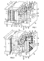
- the arm 9 of the armature which extends toward the arm 3 serving as the core of the excitation coil 2, is attracted when the excitation coil is excited, so that the other arm 10 of the armature moves away from the free arm 6 of the yoke 4. This movement of the free leg 10 is used by the actuating plate 11 to actuate the switching contacts 12 and 13 of the contact carrier 14.
- the free leg 10 of the armature 8 runs approximately parallel to the free leg 6 of the yoke 4.
- the free leg 10 has a central cutout 15 which is open at the top in FIG. 1, so that two armature actuating flaps 16 and 17 are arranged side by side. This measure serves on the one hand to reduce the moving mass of the armature 8, and on the other hand the cutout 15 exposes part of the free leg 6 of the yoke 4 which, as will be explained later, is used for fastening tasks.
- Each of the armature actuating flaps 16 and 17 has an embossing that bulges toward the free leg 6 of the yoke 4 at the end. In Figure 1, only the embossing 18 of the anchor actuation tab 16 is visible.
- the anchor actuation tabs 16 and 17 have 18 depressions above the embossments 19 and 20, engage positively in the projections 21 and 22 of the actuating plate 11.
- the opposite edge 23 of the actuating plate 11 is also provided with projections 24 and 25 which engage in correspondingly shaped recesses in the movable contact fingers 28 and 29 of the switching contacts 12 and 13. This ensures proper transmission of the armature actuation force to the movable contact fingers 28 and 29 and at the same time a solid mounting of the actuation plate 11 is achieved.
- the two switching contacts 12 and 13 are arranged side by side relative to the free leg 8 of the yoke 4.
- the full width of the relay which is mainly determined by the optimization of the magnetic flux, is thus used for the space-saving arrangement of the switching contacts and a large depth of the relay 1 is avoided.
- the switch contact 12 is designed as a make contact
- the switch contact 13 as a break contact.
- any two-way combination of the elements make contact / break contact / changeover contact can be used as switching contacts.
- the actuation plate 11 has two rectangular recesses 30 and 31, which are each arranged between the movable contact fingers 28 and 29 of the switch contacts 12 and 13 and the armature actuation tabs 16 and 17, respectively through the recess 31. These recesses 30 and 31 serve to extend the creepage distance and thus increase the insulation strength of the actuating plate 11 made of the insulating material Pertinax.
- the contact carrier 14 has a supporting web 33, in which the contact fingers of the switching contacts 12 and 13 are embedded approximately parallel to the axis of the excitation coil 2.
- the plane spanned by the support web 33 runs perpendicular to the axis of the excitation coil 2.
- the transverse dimensions of the support web 33 i. H. its dimensions in the vertical direction to the axis of the excitation coil 2 and parallel to the free leg 6 of the yoke 4 coincide with those of the excitation coil .2 in this direction.
- the support web 33 is located approximately at the height of the coil flange 34 of the excitation coil 2 facing away from the web 5 of the yoke 4.
- the support web 33 has a fastening projection 35, via which the contact carrier 14 at the point of the free between the two armature actuation tabs 16 and 17 Leg 6 of the yoke 5 is fixed by a screw by means of the fastening screw 36.
- the attachment projection 35 is cuboid and has a central bore for receiving the attachment screw 36.
- the cuboid fastening attachment 35 is placed on the supporting web 33 from above and projects in the direction of the free leg 6 of the yoke 4 over the supporting web 33.
- This holding element 37 holds the armature 8 with at least one resilient holding arm so that it can pivot in its predetermined position relative to the bearing edge 7 on the free leg 6.
- the support arms 38 and 39 descend perpendicularly from a wall 41 of the contact carrier 14, which extends perpendicularly to the end of the supporting web 33 on the free leg 6 of the yoke 4.
- This wall 41 opens into the fastening projection 35 and continues on the other side of the fastening projection 35 up to the end of the supporting web 33.
- the contact carrier 14 is symmetrical about the axis of the fastening screw 36 and the axis of the Er built up control coil containing symmetry plane.
- the side support arms 38 and 39 can also go directly from the support web 33.
- the supporting web 33 of the contact carrier 14 also merges on its side facing away from the free leg 6 of the yoke 4 into a rear wall 42 which runs parallel to the free leg 6 and which has a depression 43 for receiving the fastening screw 36.
- This rear wall serves to protect the switching contacts 12 and 13 against damage due to mechanical influences, which could impair the adjustment of the switching contacts 12 and 13.
- the supporting web 33, the wall 41, and the cuboid fastening attachment 35 in connection with the rear wall 42 form niches, - of which the greater part of the length of the switching contacts 12 and 13 is encompassed and which have a high electrical leakage current resistance to one another.
- the entire contact carrier 14, consisting of the supporting web 33, the fastening projection 35, the wall 41, the support arms 38 and 39 and the rear wall 42 is made in one piece and consists of an insulating plastic. It can be produced in an injection molding process in an advantageous manner in terms of production technology.
- the relay shown in perspective in FIG. 2 serves to illustrate an alternative embodiment for the mounting of the actuating plate 11.
- the elements of the relay that correspond to FIG. 1 are given the same reference numerals. For reasons of better clarity, a number of elements of FIG. 1 are not or only partially shown in this figure. Of the two support arms 38 and 39, only the support arm 38 is roughly schematically indicated.
- the opposite edge 23 of the actuating plate 11 has only a single projection 44 lying in the plane of the actuating plate, which engages in a guide recess 45 designed as an opening in the rear wall 42 of the contact carrier 14 and is displaceably mounted in the longitudinal direction thereof. This results in a perfect three-point bearing for the actuating plate 11. It is therefore no longer necessary to provide a plurality of projections on this edge 23 of the actuating plate 11 and recesses in the movable contact fingers 28 and 29.
- FIG. 3 shows a perspective detailed view of the contact carrier 14, the switch contacts not being shown for reasons of better clarity.
- the contact carrier 14 is of mirror-symmetrical design, the plane of symmetry containing the axis of the bore adjoining the depression 43 through the cuboid fastening attachment 35 and being perpendicular to the supporting web 33.
- the free end face of the fastening projection 35 parallel to the rear wall 42 presses the holding element 37 against the free leg 6 of the yoke 4.
- the required actuation force for the switching contacts 12 and 13 can be provided with a very small control power if the ratio of the width a of the excitation coil 2 to the width b of the as a core effective leg 3 of the yoke 4 is in a range between 1.65 and 2.0.
- the minimum tax rate is a ratio a / b of 1.75.
- a particularly favorable range is 1.75 ⁇ 0.05.
- FIGS. 1-10 Different embodiments of the actuating plate 11 are shown in FIGS.
- FIG. 4 shows the embodiment of an actuating plate 11 explained in connection with FIG. 1 for an NO contact on the left and an NC contact on the right.
- the projections 21 and 22 are provided for engagement in the armature actuation flaps 16 and 17, the projections 24 and 25 for engagement in recesses in the movable contact fingers 28 and 29 of the switching contacts 12 and 13.
- FIG. 5 shows the embodiment of the actuating plate 11 explained with reference to FIG. 2 for the same pairing of switching contacts, i. H. for a make contact and a break contact. Instead of the two projections 24 and 25, only one projection 44 is needed here, which engages in the guide recess 44 of the rear wall 42.
- FIG. 6 shows an embodiment of an actuating plate 11 for two make contacts for the three-point mounting of the actuating plate explained with reference to FIG. 2.
- FIG. 7 shows an embodiment of the actuating plate 11 for two break contacts.
- Figure 8 finally shows an embodiment of the actuating plate 11 for two changeover contacts.
- All embodiments of the actuating plate 11 have in common that they are made in one piece and are composed essentially of two rectangular partial surfaces D and C, each of which is designed in a peculiar manner in accordance with the type of switching contacts.
- FIG. 9 shows the holding element 37 for fixing the armature 8 on the bearing edge 7 of the yoke 4 together with these elements.
- the holding member 37 is located in the cutout 15 between the two anchor actuation tabs 16 and 17 on the outer surface of the free leg 6 of the tongue piece 4.
- the holding member 37 has two retaining arms 45 and 46, which extend substantially parallel to one another and end at about 135 0 to Claws 47 and 48 are curved. These claws 47 and 48 engage in depressions 49 and 50 of the armature 8.
- the depressions 49 and 50 are arranged in the region of the curvature zone 51 of the armature 8.
- the two holding arms 45 and 46 are connected to one another by a fastening web 52 which is approximately U-shaped and includes an elongated hole 53 which is open on one side.
- the fastening web 52 represents the fastening surface on which the end face of the fastening projection 35 of the contact carrier 14 is pressed in the region of the dashed line D.
- the threaded bore 54 in the free leg 6 of the yoke 4 located in the area of the elongated hole 53 serves to receive the fastening screw 36 of the contact carrier 14.
- the possibility given by the elongated hole 53 to move the holding element 37 is used to adjust the clamping force in a functional manner for fixing the armature 8 on the cutting edge 7.
- the holding element 37 has at its end facing away from the claws 47 and 48 a holding lug 55 which engages in a holding opening 56 in the free leg 6 of the yoke 4.
- the anchor 8 is thus secured in position during the assembly process by attaching the holding element 37 before attaching the screw connection in the manner of a three-point bearing.
- the holding lug 55 starts from a connecting web 57 connecting the two holding arms 45 and 46 at their end facing away from the claws 47 and 48.
- this connecting web 57 applies the main part of the initially relatively low spring force for holding the armature 8 in place.
- the holding element 37 is pressed against the free leg 6 of the yoke after the contact carrier 14 has been screwed tightly in the area of the rectangle D shown in FIG. 9, then essentially only the increased holding force of the holding element 37 mediated by the claws 47 and 48 is effective , so that the armature 8 is properly pressed against the bearing edge 7 when the relay is assembled, even in the event of shock-like mechanical loads.
- the spring constant of the holding element 37 which acts to hold the armature 8 is "switched over" to a higher value by disabling the parts 55, 57 of the holding element 37 that determine the previous spring constant.
- the holding arms 45 and 46 are connected to each other directly behind the claws 47 and 48 by a support web 58 which serves to mechanically stabilize the two holding arms 45 and 46.
- the holding arms 45 and 46 are up to the bending points 59 and 60 in one plane with the connecting web 57 and the fastening web 52 and are therefore in this area on the outer surface of the free leg 6.
- the holding arms 45 and 46 are bent back somewhat from the bending points 59 and 60 to the claws 47 and 48 relative to the outer surface of the free leg 6. This back bend is dimensioned such that a holding force is transmitted through the claws 47 and 48 to the armature 8, which holds through the bearing cutting edge.
- the armature 8 is thus fixed on the bearing cutting edge 7 so as to be pivotable, without the holding element 37 caused by the retention causing a torque on the armature 8.
- the holding element 37 is constructed with mirror symmetry.
- the plane of symmetry runs parallel to the holding arms 45 and 46 through the center line of the elongated hole 53 and is perpendicular to the plane specified by the connecting web 57 and the fastening web 52.
Landscapes
- Physics & Mathematics (AREA)
- Electromagnetism (AREA)
- Electromagnets (AREA)
- Electronic Switches (AREA)
- Seal Device For Vehicle (AREA)
- Control Of Motors That Do Not Use Commutators (AREA)
- Developing Agents For Electrophotography (AREA)
- Addition Polymer Or Copolymer, Post-Treatments, Or Chemical Modifications (AREA)
- Valve Device For Special Equipments (AREA)
- Fittings On The Vehicle Exterior For Carrying Loads, And Devices For Holding Or Mounting Articles (AREA)
- Valve-Gear Or Valve Arrangements (AREA)
Abstract
Description
- Die Erfindung betrifft ein Relais, bestehend aus einer Erregerspule, aus einem u-förmigen Rückschlußbügel, dessen einer Schenkel als Kern der Erregerspule dient, aus einem Anker zur Betätigung mindestens eines Schaltkontaktes eines Kontaktträgers, der einen annähernd senkrecht zur Achse der Erregerspule verlaufenden Tragsteg zur Befestigung der Kontaktfinger jedes Schaltkontaktes aufweist, wobei der Kontaktträger am freien Schenkel des Rückschlußbügels befestigt ist, und wobei _ eine Kante der Stirnfläche des freien Schenkels des Rückschlußbügels als Lagerschneide für den Anker dient, der durch ein Halteelement am freien Schenkel des Rückschlußbügels befestigt ist.
- Ein derartiges Relais ist im Handel erhältlich. Dieses Relais weist einen plattenförmigen Anker auf, der senkrecht zur Achse der Erregerspule und zum freien Schenkel des Rückschlußbügels angeordnet ist. Als Halteelement dienen zwei senkrecht zur Ebene des Ankers verlaufende, diesen durchstoßende Haltestifte, die durch eine Andruckplatte am freien Schenkel des Befestigungsbügels durch eine Schraubbefestigung angepreßt sind. Der Anker greift mit Betätigungsfingern an seinem dem Kern der Erregerspule abgewandten Ende über den freien Schenkel des Rückschlußbügels hinaus. Ein voluminöser Kontaktträger umgreift die aus Erregerspule, Rückschlußbügel, sowie Anker bestehende Betätigungseinheit von vier Seiten und ist durch zwei Schrauben mit dem freien Schenkel des Rückschlußbügels verbunden. Der Kontaktträger weist unter anderem einen senkrecht zur Achse der Erregerspule verlaufenden Tragsteg auf, auf dem mehrere Isolierstoffplatten durch zwei Verschraubungen befestigt sind. Zwischen den Isolierstoffplatten sind die Kontaktfinger mehrerer Schaltkontakte eingespannt, so daß die Kontaktfinger senkrecht zur Achse der Erregerspule verlaufen. Die Kontaktfinger greifen erheblich über die Betätigungsfinger des Ankers hinaus,so daß dieses bekannte Relais einen erheblichen Raumbedarf aufweist. Darüberhinaus ist dieses Relais durch die Vielzahl der notwendigen Verschraubungen relativ aufwendig in der Montage.
- Ein weiteres im Handel befindliches Relais weist eine zylindrische Erregerspule mit einem zylindrischen Kern auf. Der Kern der Erregerspule greift einseitig über den Spulenflansch hinaus und ist mit einer Isolierstoffplatte vernietet. Ein L-förmiger Rückschlußbügel liegt mit seinem Fuß am überstehenden Ende des Kerns der Erregerspule an und ist zwischen dem einen Spulenflansch und der Isolierstoffplatte eingeklemmt. Dieser Rückschlußbügel stützt sich an seiner der Erregerspule abgewandten Außenfläche an einer Schulter der Isolierstoffplatte ab, deren Verlängerung gleichzeitig als Kontaktträger für drei hintereinander angeordnete Kontaktfinger eines Umschaltkontaktes dient. Der freie Schenkel des Rückschlußbügels weist endseitig eine rechteckige Ausnehmung auf, durch die ein winkelförmiger Anker hindurchgreift, dessen freier Schenkel im wesentlichen parallel zum freien Schenkel des Rückschlußbügels verläuft. Eine in der Ausnehmung des freien Schenkels des Rückschlußbügels angebrachte Spannfeder dient als Halteelement für den Anker und preßt diesen gegen eine als Lagerschneide dienende Kante der Stirnfläche des freien Schenkels des Rückschlußbügels. Der freie Schenkel des Ankers weist einen zentralen Ausschnitt zur Bildung von zwei seitlichen Ankerbetätigungslappen auf, die durch eine Isolierstoffbrücke verbunden sind. Die Isolierstoffbrücke weist eine zentrale Ausnehmung auf, in die ein im wesentlichen kreuzförmiges Betätigungselement eingreift, das durch eine Ausnehmung des einen Kontaktfingers des Wechselkontaktes hindurchgreift und sich mit dem Querbalken der Kreuzform am mittleren Kontaktfinger abstützt. Bei diesem Relais tritt wegen des zusätzlichen Luftspaltes zwischen dem Kern der Erregerspule und dem L-förmigen Rückschlußbügel keine optimale Führung des magnetischen Flusses auf, so daß zu seiner Ansteuerung eine erhebliche Schaltleistung aufgebracht werden muß. Darüberhinaus weist dieses Relais eine erhebliche Bauhöhe auf, da der Spulenkörper der Erregerspule durch den als Isolierstoffplatte ausgebildeten Kontaktträger untergriffen wird.
- Der Erfindung liegt die Aufgabe zugrunde, ein Relais der eingangs genannten Art so auszugestalten, daß es Kompaktheit und Montagefreundlichkeit mit einem geringen Bedarf an',Steuerleistung verbindet.
- Die Aufgabe wird erfindungsgemäß dadurch gelöst, daß der Anker winkelförmig ausgebildet ist, daß der nicht mit dem Kern der Erregerspule zusammenwirkende freie Schenkel des Ankers im wesentlichen parallel zum freien Schenkel des Rückschlußbügels verläuft, daß die Kontaktfinger jedes Schaltkontaktes annähernd parallel zur Achse der Erregerspule angeordnet und im Tragsteg befestigt sind und daß der Tragsteg ein Befestigungsansatz aufweist, über den der Kontaktträger an dem vom freien Schenkel des Ankers nicht überdeckten Teil des freien Schenkels des Rückschlußbügels befestigt ist.
- Durch die winkelförmige Gestaltung des Ankers, durch die zum freien Schenkel des Rückschlußbügels annähernd parallele Anordnung des freien Schenkels des Ankers und durch den annähernd parallelen Verlauf der Kontaktfinger zur Achse der Erregerspule wird ein sehr raumökonomischer Aufbau des Relais ermöglicht. Die Befestigung der Kontaktfinger im Tragsteg und durch das Vorsehen des Befestigungsansatzes, durch den der Kontaktträger an dem vom freien Schenkel des Ankers nicht überdeckten Teil des freien Schenkels des Rückschlußbügels befestigbar ist, wird neben dem kompakten Aufbau eine hohe Montagefreundlichkeit erreicht. Darüberhinaus .führt der u-förmige Rückschlußbügel in einstückiger Ausführung gegenüber dem in der Beschreibungseinleitung an zweiter Stelle genannten bekannten Relais zu einer Verringerung der Luftspalte im magnetischen Kreis, so daß eine optimale Führung des magnetischen Flusses und damit eine hohe Ankerbetätigungskraft bei minimaler Ansteuerleistung erreicht ist.
- Es ist vorteilhaft, wenn der Kontaktträger durch eine einzige Schraube am freien Schenkel des Rückschlußbügels befestigt ist. Dies erleichtert den Fertigungs- und Mon- tageaufwand.
- In einer vorteilhaften Ausführungsform ist eine Betätigungsplatte vorgesehen, die eine mechanische Wirkverbindung zwischen dem freien Schenkel des Ankers und einem Kontaktfinger jedes Schaltkontaktes herstellt. Diese Betätigungsplatte dient der einwandfreien Übertragung der Ankerbetätigungskraft auf den beweglichen Kontaktfinger jedes Schaltkontaktes. Als Werkstoff für die Betätigungsplatte kann vorteilhaft Isolierstoff gewählt werden, da dessen mechanische Eigenschaften für die auftretenden Betätigungskräfte voll ausreichend sind und damit ohne weitere Maßnahmen eine gute Isolation zwischen Kontaktfinger und Anker erreicht ist. Darüberhinaus wird durch das geringe Gewicht dieses Werkstoffes ein trägheitsarmes Ansprechen des Relais begünstigt.
- Die Betätigungsplatte kann zwischen mindestens einem Schaltfinger jedes Schaltkontaktes und dem freien Schenkel des Ankers Ausnehmungen aufweisen. Diese Ausnehmungen dienen der Verbesserung der Isolation durch Verlängerung der Kriechstromwege. Darüberhinaus kann durch diese Ausnehmung bei der Ausführung der Schaltkontakte als Öffnerkontakt oder als Wechslerkontakt der jeweils unbewegliche Schaltfinger durch diese Ausnehmung hindurchragen, wodurch ebenfalls der raumökonomische Aufbau des Relais begünstigt wird.
- In einer bevorzugten Ausführungsform ist der Kontaktträger mit einem an dem dem freien Schenkel des Rückschlußbügels abgewandten Ende des Tragsteges mit einer in Richtung der Achse der Erregerspule verlaufenden Rückwand zur Bildung einer L-förmigen Struktur versehen. Diese Rückwand schützt die Kontaktfinger der Schaltkontakte gegen ungewollte mechanische Einwirkungen und Beschädigungen.
- Es ist vorteilhaft, wenn der freie Schenkel des Ankers einen zentralen Ausschnitt zur Bildung von zwei Ankerbetätigungslappen aufweist. Damit wird einerseits durch eine Massenverringerung des Ankers und damit Reduktion des Trägheitsmomentes eine hohe Betätigungsgeschwindigkeit des Relais erreicht. Darüberhinaus entsteht zwischen den Ankerbetätigungslappen eine freie Fläche des freien Schenkels des Rückschlußbügels, an dem der Befestigungsansatz des Kontaktträgers anliegen und verschraubt werden kann, so daß diese Maßnahme letztlich ebenfalls den raumökonomischen Aufbau des Relais begünstigt.
- Eine bevorzugte Ausführungsform des Relais besteht darin, daß die Ankerbetätigungslappen Vertiefungen aufweisen, in die Vorsprünge der Betätigungsplatte eingreifen und daß ein weiterer Vorsprung der Betätigungsplatte in eine Führungsvertiefung der Rückwand eingreift. Damit ist eine mechanisch günstige Dreipunktführung der Betätigungsplatte - unabhängig von der Anzahl der zu betätigenden Schaltkontakte - erreicht.
- Eine alternative vorteilhafte Ausführungsform besteht darin, daß die Ankerbetätigungslappen Vertiefungen aufweisen, in die Vorsprünge der Betätigungsplatte eingreifen und daß in eine Ausnehmung zumindest eines beweglichen Kontaktfingers eines Schaltkontaktes ein weiterer Vorsprung der Betätigungsplatte eingreift. Damit ist es jedoch erforderlich, zumindest in einem Kontaktfinger eine Ausnehmung vorzusehen, was dessen Stromtragfähigkeit ungünstig beeinflussen kann. Darüberhinaus ist es bei dem die Ausnehmung aufweisenden Kontaktfinger schwieriger, die Justierung eines Mindestabstandes, beispielsweise um den Abbrand zu kompensieren, zwischen Kontaktfinger und Betätigungsplatte einzustellen, da eine optische Kontrolle dieses Abstandes nicht mehr ohne weiteres möglich ist.
- Eine weitere bevorzugte Ausführungsform des erfindungsgemäßen Relais besteht darin, daß der Befestigungsansatz am Ort des zentralen Ausschnittes des freien Schenkels des Ankers am freien Schenkel des Rückschlußbügels anliegt und durch die Schraube mit dem Rückschlußbügel verbunden ist.
- Der Befestigungsansatz kann quaderförmig gestaltet sein und eine zentrale Bohrung zur Aufnahme der Befestigungsschraube aufweisen. Darüberhinaus kann der Befestigungsansatz in Richtung auf den freien Schenkel des Rückschlußbügels hin über den Tragsteg überstehen. Damit ist ein ausreichender Freiraum für die freie Bewegung der Ankerbetätigungslappen in Richtung auf die Schaltkontakte hin sichergestellt.
- Es ist vorteilhaft, wenn das Halteelement für den Anker blattfederartig gestaltet ist,und zumindest mit einem Teil seiner Fläche am freien Schenkel des Rückschlußbügels anliegend befestigt ist, wobei das Halteelement den Anker mit mindestens einem federnden Haltearm in seiner vorgegebenen Stellung relativ zum freien Schenkel des Rückschlußbügels hält. Damit ist eine die notwendige Schwenkbeweglichkeit des Ankers gewährleistende Halterung des Ankers am Rückschlußbügel erreicht.
- Hierbei ist es besonders vorteilhaft, wenn das Halteelement eine Befestigungsfläche aufweist, die durch den Befestigungsansatz des Kontaktträgers an den freien Schenkel des Rückschlußbügels angepreßt ist. Damit ist zugleich mit der Schraubbefestigung des Kontaktträgers am freien Schenkel des Rückschlußbügels auch die schwenkbewegliche Befestigung des Ankers ermöglicht. Dies stellt, da nur eine einzige Verschraubung benötigt wird, eine sehr montagefreundliche Lösung dar.
- Das Halteelement kann zwei endseitig krallenartig abgekrümmte Haltearme aufweisen, die in Einsenkungen im Bereich der Krümmungszone des Ankers eingreifen und diesen gegen die Lagerschneide des freien Schenkels des Rückschlußbügels andrücken. Durch diesen Zweipunkt-Kraftangriff ist eine besonders zuverlässige und verkippungsfreie Halterung des Ankers erreicht,'wodurch auch eine optimale Führung des magnetischen Flusses über den nunmehr reproduzierbar vorgegebenen Luftspalt zwischen Anker und Stirnfläche des freien Schenkels des Rückschlußbügels ermöglicht ist. Da die durch die Haltearme vermittelte Kraftwirkung im Bereich der Krümmungszone des Ankers erfolgt, wird durch die Haltekraft nahezu kein zusätzliches Drehmoment auf den Anker ausgeübt.
- Aus der Befestigungsfläche des Halteelementes kann eine Haltenase abstehen, die in eine Halteöffnung im freien Schenkel des Rückschlußbügels eingreift. Damit wird bei der Montage des Relais vor der endgültigen Festlegung des Halteelementes,durch die Verschraubung des Kontaktträgers bereits eine Festlegung des Ankers erreicht, so daß vor der nachfolgenden Anbringung des Kontaktträgers ein Herabgleiten des Ankers aus seiner vorgegebenen Stellung am Rückschlußbügel ausgeschlossen ist.
- In einer bevorzugten Ausführungsform ist der Kontaktträger mit zwei Schaltkontakten bestückt, die zu beiden Seiten einer die Achse der Erregerspule enthaltenden und senkrecht durch den Tragsteg verlaufenden Bezugsebene angeordnet sind. Durch diese Nebeneinanderanordnung der Schaltkontakte ist eine geringe Bautiefe des Relais möglich.
- Als Schaltkontakte kann eine beliebige Zweierkombination aus den drei Elementen Schließkontakt, Öffnerkontakt und Wechselkontakt eingesetzt sein.
- Eine bevorzugte Ausführungsform des erfindungsgemäßen Relais besteht darin, daß die einstückige Betätigungsplätte aus zwei rechteckförmigen Teilflächen besteht, wobei jeweils eine geradlinige Außenkante zur Betätigung des beweglichen Kontaktfingers des Schaltkontaktes dient und wobei bei einem Öffnerkontakt der feststehende Kontaktfinger berührungslos durch die zugeordnete Ausnehmung der Betätigungsplatte hindurchragt. Die Wahl der geradlinigen Außenkante zur Betätigung des beweglichen Kontaktfingers gestattet eine leichte optische Kontrolle der Anlage bzw. des erforderlichen Abstandes zwischen beweglichem Kontaktfinger und Außenkante der Betätigungsplatte bei der Justierung der Schaltkontakte.
- In einer bevorzugten Ausführungsform weist der Kontaktträger zumindest einen seitlichen Stützarm auf, der den freien Schenkel des Rückschlußbügels übergreift und den Spulenflansch der Erregerspule, der mit seiner Außenseite sich an dem die beiden Schenkel des Rückschlußbügels verbindenden Steg abstützt, an der Innenfläche untergreift. Damit ist durch den Kontaktträger gleichzeitig die Halterung der Erregerspule auf dem Rückschlußbügel erreicht und zwar in einer außerordentlich montagefreundlichen Weise; denn durch die einzige Schraubbefestigung, durch die der Kontaktträger am freien Schenkel des Rückschlußbügels befestigt ist, erfolgt gleichzeitig die schwenkbewegliche Halterung des Ankers über das blattfederartige Halteelement und zudem noch über den seitlichen Stützarm die Festlegung der Erregerspule auf dem Rückschlußbügel. Da diese einzige Schraubbefestigung sehr leicht lösbar ist, können auch bei Beschä- digungen einzelner Elemente des Relais diese sei es die Erregerspule, die Betätigungsplatte, der Kontaktträger oder das blattfederartige Halteelement - jederzeit mit geringstmöglichen Aufwand ersetzt werden.
- Es ist besonders vorteilhaft, wenn der Kontaktträger zwei parallele Stützarme aufweist, die bündig von außen am freien Schenkel des Rückschlußbügels anliegen. Damit erfolgt eine besonders zuverlässige und verkippungsfreie Festlegung der Erregerspule auf dem Rückschlußbügel. Darüberhinaus ist durch die beiden Haltearme eine vollkommene Sicherheit gegen Verdrehung des Kontaktträgers um die Achse der Schraube erreicht. Durch die bündige Anlage der beiden parallelen Stützarme wird auch die Montage begünstigt, da nach dem Aufstecken des Kontaktträgers auf den Rückschlußbügel bereits eine Art Klemmbefestigung zustande kommt.
- Aus Gründen der Isolationssicherheit sowie aus fertigungstechnischen Gründen ist es vorteilhaft, wenn der Kontaktträger aus einem isolierenden Kunststoff besteht und einstückig gefertigt ist und wenn die Betätigungsplatte aus Pertinax gefertigt ist.
- Die Erfindung wird im folgenden anhand von Ausführungsi beispielen in den Figuren 1 bis 9 näher erläutert. Dabei zeigt:
- Figur 1 das erfindungsgemäße Relais in perspektivischer Darstellung,
- Figur 2 eine weitere Ausführungsform des Relais in perspektivischer Darstellung mit einer abgewandelten Betätigungsplatte,
- Figur 3 den Kontaktträger ohne Schaltkontakte für die in Figur 2 dargestellte Ausführungsform in perspektivischer Darstellung,
- Figur 4 eine Ausführungsform der Betätigungsplatte für einen Öffnerkontakt und einen Schließerkontakt,
- Figur 5 eine weitere Ausführungsform der Betätigungsplatte für einen Öffnerkontakt und einen Schließkontakt,
- Figur 6 eine Ausführungsform der Betätigungsplatte für zwei Schließkontakte,
- Figur 7 eine Ausführungsform der Betätigungsplatte für zwei Öffnerkontakte,
- Figur 8 eine Ausführungsform der Betätigungsplatte für zwei Wechslerkontakte und
- Figur 9 eine Darstellung des blattfederartigen Halteelementes für den Anker in der Montagestellung.
- In Figur 1 ist das erfindungsgemäße Relais mit dem Bezugszeichen 1 belegt. Die im Querschnitt rechteckige oder ovale Erregerspule trägt das Bezugszeichen 2. Die Erregerspule 2 sitzt auf dem einen Schenkel 3 des U-förmigen Rückschlußbügels.4. Der Schenkel 3 des Rückschlußbügels 4 dient als Kern der Erregerspule 2. Der eine Schenkel des Rückschlußbügels 4 ist durch einen Steg 5 mit dem freien Schenkel 6 des Rückschlußbügels verbunden. Die beiden Schenkel 3 und 6 des Rückschlußbügels 4 verlaufen im wesentlichen parallel zueinander. Ferner ist der Rückschlußbügel 4 so gestaltet, daß alle Querschnitte durch seine Schenkel 4 und 6 senkrecht zur Achse der Erregerspule 2 die Form eines schmalen Rechteckes aufweisen. Darüberhinaus sind der Steg 5 sowie der freie Schenkel 6 des Rückschlußbügels gegenüber dem in die Erregerspule 2 eintauchenden Schenkel 3 in Querrichtung verbreitert, um eine günstige Führung des magnetischen Flusses zu gewährleisten. Dem gleichen Ziel dient die einstückige Ausführung des Rückschlußbügels 5, da damit gegenüber einer mehrstückigen Ausführung mit einer Trennung in Kern und Rückschlußbügel störende Luftspalte vermieden sind. Die endseitige Außenkante des freien Schenkels 6 des Rückschlußbügels 4 dient als Lagerschneide 7 für den winkelförmig ausgebildeten Anker 8.
- Der von der Lagerschneide 7 sich zum Kern 3 der Erregerspule 2 hin erstreckende Schenkel 9 des Ankers 8 verjüngt sich in Richtung zum Kern 3 bis auf dessen Breite am Kernort und weist somit Trapezform auf. Am Ort der Lagerschneide 7 ist der Schenkel 9 des Ankers 8 ebenso breit ausgeführt wie der freie Schenkel 6 des Rückschlußbügels 4. Diese Formgebung trägt zur optimalen Führung des magnetischen Flusses bei und gewährleistet einen kleinen magnetischen Übergangswiderstand am Ort der Lagerschneide 7. Die Verjüngung des Schenkels 9 am Ort des Kernes 3 bewirkt eine Verringerung der bewegten Masse des Ankers und zieht damit eine erhebliche Verringerung des Trägheitsmomentes nach sich. Querschnitte durch den Schenkel 9 parallel zum freien Schenkel 6 des Rückschlußbügels weisen Rechteckform auf.
- Der Winkel zwischen dem Schenkel 9 und dem freien Schenkel 10 ist am Ort der Lagerschneide 7 etwas größer als 90°. Oberhalb der Lagerschneide weist der freie Schenkel 10 des Ankers 8 entlang der Biegelinie A eine weitere schwache Biegung zum freien Schenkel 6 des Rückschlußbügels 4 hin auf. Der zu dem als Kern der Erregerspule 2 dienende Schenkel 3 hin verlaufende Schenkel 9 des Ankers wird bei Erregung der Erregerspule angezogen, so daß der andere Schenkel 10 des Ankers sich vom freien Schenkel 6 des Rückschlußbügels 4 entfernt. Diese Bewegung des freien Schenkels 10 wird durch die Betätigungsplatte 11 zur Betätigung der Schaltkontakte 12 und 13 des Kontaktträgers 14 genutzt.
- Der freie Schenkel 10 des Ankers 8 verläuft annähernd parallel zum freien Schenkel 6 des Rückschlußbügels 4. Der freie Schenkel 10 weist einen zentralen, in Figur 1 nach oben hin offenen Ausschnitt 15 auf, so daß zwei seitlich nebeneinander angeordnete Ankerbetätigungslappen 16 und 17 entstehen. Diese Maßnahme dient einerseits der Reduktion der bewegten Masse des Ankers 8, andererseits wird durch den Ausschnitt 15 ein Teil des freien Schenkels 6 des Rückschlußbügels 4 freigelegt, der - wie später erläutert wird - für Befestigungsaufgaben genutzt wird. Jeder der Ankerbetätigungslappen 16 und 17 weist endseitig eine zum freien Schenkel 6 des Rückschlußbügels 4 hin sich vorwölbende Prägung auf. In Figur 1 ist lediglich die Prägung 18 des Ankerbetätigungslappens 16 sichtbar. Durch diese Prägung ist eine definierte, kleinflächige Anlage des freien Schenkels 10 des Ankers 8 am freien Schenkel 6 des Rückschlußbügels 4 erreicht, so daß an diesen Stellen ein vergleichsweiser großer magnetischer Widerstand und eine schlechte Führung des magnetischen Flusses auftritt, so daß bei Betätigung des Relais nur eine kleine Abreißkraft an dieser Stelle auftritt. In Figur 1 weisen die Ankerbetätigungslappen 16 und 17 oberhalb der Prägungen 18 Vertiefungen 19 und 20 auf, in die Vorsprünge 21 und 22 der Betätigungsplatte 11 formschlüssig eingreifen. Auch die gegenüberliegende Kante 23 der Betätigungsplatte 11 ist mit Vorsprüngen 24 und 25 versehen, die in entsprechende formangepaßte Ausnehmungen in den beweglichen Kontaktfingern 28 und 29 der Schaltkontakte 12 und 13 eingreifen. Damit ist eine einwandfreie Übertragung der Ankerbetätigungskraft auf die beweglichen Kontaktfinger 28 und 29 gesichert und gleichzeitig eine solide Lagerung der Betätigungsplatte 11 erreicht.
- In dem in Figur 1 dargestellten Ausführungsbeispiel sind die beiden Schaltkontakte 12 und 13 relativ zum freien Schenkel 8 des Rückschlußbügels 4 nebeneinanderliegend angeordnet. Damit wird die volle Breite des Relais, die überwiegend durch die Optimierung des magnetischen Flusses vorgegeben ist, für die raumökonomische Anordnung der Schaltkontakte genutzt und eine große Bautiefe des Relais 1 vermieden. In dem in Figur 1 dargestellten Ausführungsbeispiel ist der Schaltkontakt 12 als Schließkontakt, der Schaltkontakt 13 als Öffnerkontakt ausgeführt. Allerdings ist anzumerken, daß als Schaltkontakte jede beliebige Zweierkombination der Elemente Schließkontakt/Öffnerkontakt/Wechslerkontakt einsetzbar ist.
- Die Betätigungsplatte 11 weist zwei rechteckige Ausnehmungen 30 und 31 auf, die jeweils zwischen dem beweglichen Kontaktfinger 28 bzw. 29 der Schaltkontakte 12 und 13 und der Ankerbetätigungslappen 16 bzw. 17 angeordnet sind, Im Falle des als Öffnerkontakt ausgeführten Schaltkontaktes 13 greift der unbewegliche Kontaktfinger 32 durch die Ausnehmung 31 hindurch. Diese Ausnehmungen 30 und 31 dienen der Kriechwegverlängerung und erhöhen somit die Isolationsfestigkeit der aus dem Isolierstoff Pertinax gefertigten Betätigungsplatte 11.
- Der Kontaktträger 14 weist einen Tragsteg 33 auf, in dem die Kontaktfinger der Schaltkontakte 12 und 13 annähernd parallel zur Achse der Erregerspule 2 eingelassen sind. Die durch den Tragsteg 33 aufgespannte Ebene verläuft senkrecht zur Achse der Erregerspule 2. Die Querabmessungen des Tragsteges 33, d. h. seine Abmessungen in senkrechter Richtung zur Achse der Erregerspule 2 und parallel zum-freien Schenkel 6 des Rückschlußbügels 4 decken sich mit denen der Erregerspule .2 in dieser Richtung. Der Tragsteg 33 befindet sich etwa auf der Höhe des dem Steg 5 des Rückschlußbügels 4 abgewandten Spulenflansches 34 der Erregerspule 2. Der Tragsteg 33 weist einen Befestigungsansatz 35 auf, über den der Kontaktträger 14 an der zwischen den beiden Ankerbetätigungslappen 16 und 17 freiliegenden Stelle des freien Schenkels 6 des Rückschlußbügels 5 durch eine Verschraubung mittels der Befestigungsschraube 36 befestigt ist. In dem in Figur 1 dargestellten Ausführungsbeispiel ist der Befestigungsansatz 35 quaderförmig gestaltet und weist eine zentrale Bohrung zur Aufnahme der Befestigungsschraube 36 auf. Der quaderförmige Befestigungsansatz 35 ist von oben auf den Tragsteg 33 aufgesetzt und steht in Richtung auf den freien Schenkel 6 des Rückschlußbügels 4 hin über den Tragsteg 33 vor. Die viereckige, dem freien Schenkel 6 zugewandte Stirnfläche des Befestigungsansatzes 35 preßt zumindest einen Teil eines blattfederartig gestalteten Halteelementes für den Anker 8, das sich ebenfalls in dem Ausschnitt 15 zwischen den beiden Ankerbetätigungs2iappen 16 und 17 befindet, gegen den freien Schenkel 6 des Rückschlußbügels 4. Dieses Halteelement 37 hält den Anker 8 mit mindestens einem federnden Haltearm schwenkbeweglich in seiner vorgegebenen Stellung relativ zur Lagerschneide 7 am freien Schenkel 6 fest. Der Aufbau des Halteelementes wird noch im folgenden anhand der Figur 9 näher erläutert.
- An den Tragsteg 33 des Kontaktträgers 14 sind seitlich annähernd parallele Stützarme 38 und 39 angebracht, die senkrecht zum Tragsteg 33 angeordnet sind und in Richtung zur Erregerspule 2 hin verlaufen. Die beiden Stützarme 38 und 39 sind so dimensioniert, daß sie im angeschraubten Zustand des Kontaktträgers 14 mit leichten Druck zum Steg 5 des Rückschlußbügels hin den diesem Steg zugewandten Spulenflansch 40 der Erregerspule 2 untergreifen und gegen den Steg 5 pressen. Damit erfolgt gleichzeitig mit der Schraubbefestigung des KontaHtträgers 14 am freien Schenkel 6 des Rückschlußbügels 4 auch eine zuverlässige und montagefreundliche Fixierung der Erregerspule 2 in ihrer vorgegebenen Lage. Dies stellt einen erheblichen Vorteil gegenüber bisher bekannten Relais dar, bei denen zur Fixierung der Erregerspule entweder zusätzliche Schraubbefestigungen, Vernietungen oder Verklebungen für notwendig gehalten wurden. Dadurch daß die beiden Stützarme 38 und 39 bezüglich ihres Abstandes so angeordnet sind, daß sie bündig von außen am freien Schenkel 6 des Rückschlußbügels 4 anliegen, wird zum einen die Verdrehungsfreiheit des Kontaktträgers 14 erreicht, zum anderen die Montage erleichtert, da bereits vor dem Einbringen der Befestigungsschraube 36 der Kontaktträger 14 in einem durch die beiden Stützarme 38 und 39 vermit# telten Klemmkontakt auf den freien Schenkel 6 des Rückschlußbügels aufsetzbar ist.
- Im vorliegenden Fall gehen die Stützarme 38 und 39 senkreoht von einer Wandung 41 des Kontaktträgers 14 ab, die an dem dem freien Schenkel 6 des Rückschlußbügels 4 zugewandten Ende des Tragsteges 33 senkrecht zu diesem verläuft. Diese Wandung 41 mündet in den Befestigungsansatz 35 ein und setzt sich auf der anderen Seite des Befestigungsansatzes 35 bis zum Ende des Tragsteges 33 fort. Der Kontaktträger 14 ist symmetrisch zu der die Achse der Befestigungsschraube 36 und die Achse der Erregerspule enthaltenden Symmetrieebene aufgebaut. Die seitlichen Stützarme 38 und 39 können auch direkt vom Tragsteg 33 aus abgehen.
- Der Tragsteg 33 des Kontaktträgers 14 geht ferner an seiner dem freien Schenkel 6 des Rückschlußbügels 4 abgewandten Seite in eine parallel zum freien Schenkel 6 verlaufende Rückwand 42 über, die zur Aufnahme der Befestigungsschraube 36 eine Einsenkung 43 aufweist. Diese Rückwand dient dem Schutz der Schaltkontakte 12 und 13 gegen Beschädigung durch mechanische Einwirkungen, durch die die Justierung der Schaltkontakte 12 und 13 beeinträchtigt werden könnte. Darüberhinaus bilden der Tragsteg 33, die Wandung 41, sowie der quaderförmige Befestigungsansatz 35 in Verbindung mit der Rückwand 42 Nischen,--von denen der größere Teil der Länge der Schaltkontakte 12 und 13 umfangen ist und die eine hohe elektrische Kriechstromfestigkeit gegeneinander aufweisen.
- Der gesamte Kontaktträger 14, bestehend aus Tragsteg 33, aus Befestigungsansatz 35, aus der Wandung 41, aus den Stützarmen 38 und 39 sowie der Rückwand 42 ist einstückig ausgeführt und besteht aus einem isolierenden Kunststoff. Er kann in fertigungstechnisch vorteilhafter Weise im Spritzgießverfahren hergestellt sein.
- Das in Figur 2 perspektivisch dargestellte Relais dient der Veranschaulichung einer alternativen Ausführungsform für die Lagerung der Betätigungsplatte 11. Die mit Figur 1 übereinstimmenden Elemente des Relais sind mit übereinstimmenden Bezugszeichen belegt. Aus Gründen der besseren Übersichtlichkeit sind in dieser Figur eine Reihe von Elementen der Figur 1 nicht oder nur teilweise dargestellt. Von den beiden Stützarmen 38 und 39 ist nur der Stützarm 38 grob schematisch angedeutet.
- Wie in dem in Figur 1 dargestellten Fall greifen die zum freien Schenkel 6 des Rückschlußbügels 4 hin gerichteten Vorsprünge 21 und 22 der Betätigungsplatte 11 in zugehörige, formangepaßte Vertiefungen 19 und 20 der Ankerbetätigungslappen 16 und 17 ein. Die gegenüberliegende Kante 23 der Betätigungsplatte 11 weist jedoch nur einen einzigen, in der Ebene der Betätigungsplatte liegenden Vorsprung 44 auf, der in eine als Durchbruch ausgeführte Führungsvertiefung 45 in der Rückwand 42 des Kontaktträgers 14 eingreift und in dieser in Längsrichtung verschiebbar gelagert ist. Damit ist eine einwandfreie Dreipunktlagerung für die Betätigungsplatte 11 herbeigeführt. Somit ist es nicht mehr erforderlich, an dieser Kante 23 der Betätigungsplatte 11 mehrere Vorsprünge und in den beweglichen Kontaktfingern 28 und 29 Ausnehmungen vorzusehen. Damit ist die Fertigung des Relais vereinfacht. Barüberhinaus ist damit eine einfache Sichtprüfung der konekten Justierung der Kontaktfinger ermöglicht; denn im Falleedes als Öffnerkontakt ausgeführten Schaltkontaktes 13 ist es - um den während der Betriebsdauer auftretenden Abbrand der Kontakte zu kompensieren -o erforderlich, daß der bewegliche Kontaktfinger 29 einen Abstand von etwa 1/10 mm zur Kante 23 der Betätigungsplatte aufweist.
- Figur 3 zeigt in einer perspektivischen Detaildarstellung den Kontaktträger 14, wobei aus Gründen der besseren Übersichtlichkeit die Schaltkontakte nicht eingezeichnet wurden. Der Kontaktträger 14 ist spiegelsymmetrisch aufgebaut, wobei die Symmetrieebene die Achse der sich an die Einsenkung 43 anschließenden Bohrung durch den quaderförmigen Befestigungsansatz 35 enthält und senkrecht zum Tragsteg 33 beläuft. Die zur Rückwand 42 parallele freie Stirnfläche des Befestigungsansatzes 35 preßt das Halteelement 37 gegen den freien Schenkel 6 des Rückschlußbügels 4.
- Umfangreiche und langwierige empirische und theoretische Untersuchungen erbrachten das Ergebnis, daß bei vorgegebener Breite a der Erregerspule 2 die erforderliche Betätigungskraft für die Schaltkontakte 12 und 13 mit einer sehr kleinen Steuerleistung erbracht werden kann, wenn das Verhältnis von Breite a der Erregerspule 2 zur Breite b des als Kern wirksamen Schenkels 3 des Rückschlußbügels 4 in einem Breich zwischen 1,65 und 2,0 liegt. Das Minimum der Steuerleistung liegt bei einem Verhältnis a/b von 1,75. Ein besonders günstiger Bereich liegt bei 1,75 ± 0,05.
- In den Figuren 4 bis 8 sind unterschiedliche Ausführungsformen der Betätigungsplatte 11 dargestellt.
- Figur 4 zeigt die in Verbindung mit.Figur 1 erläuterte Ausführungsform einer Betätigungsplatte 11 für links liegend einen Schließerkontakt und rechts liegend einen Öffnerkontakt. Die Vorsprünge 21 und 22 sind zum Eingriff in die Ankerbetätigungslappen 16 und 17 vorgesehen, die Vorsprünge 24 und 25 zum Eingriff in Ausnehmungen in den beweglichen Kontaktfingern 28 und 29 der Schaltkontakte 12 und 13.
- Figur 5 zeigt die anhand von Figur 2 erläuterte Ausführungsform der Betätigungsplatte 11 für die gleiche Paarung von Schaltkontakten, d. h. für einen SchlieBkontakt und einen Öffnerkontakt. An Stelle der beiden Vorsprünge 24 und 25 wird hier nur noch ein Vorsprung 44 benötigt, der in die Führungsvertiefung 44 der Rückwand 42 eingreift.
- Figur 6 zeigt eine Ausführungsform einer Betätigungsplatte 11 für zwei Schließkontakte für die anhand von Figur 2 erläuterte Dreipunktlagerung der Betätigungsplatte.
- Figur 7 zeigt eine Ausführungsform der Betätigungsplatte 11 für zwei Öffnerkontakte.
- Figur 8 schließlich zeigt eine Ausführungsform der Betätigungsplatte 11 für zwei Wechslerkontakte.
- Allen Ausführungsformen der Betätigungsplatte 11 ist gemeinsam, daß sie einstückig ausgeführt sind und im wesentlichen aus zwei rechteckförmigen Teilflächen D und C zusammengesetzt sind, die jeweils entsprechend der Art der Schaltkontakte eigenartig ausgeführt sind.
- In Figur 9 schließlich ist das Halteelement 37 zur Fixierung des Ankers 8 auf der Lagerschneide 7 des Rückschlußbügels 4 zusammen mit diesen Elementen dargestellt. Das Halteelement 37 liegt in dem Ausschnitt 15 zwischen den beiden Ankerbetätigungslappen 16 und 17 auf der Außenfläche des freien Schenkels 6 des Rückschlußbügels 4. Das Halteelement 37 weist zwei Haltearme 45 und 46 auf, die im wesentlichen parallel zueinander verlaufen und endseitig um etwa 1350 zu Krallen 47 und 48 abgekrümmt sind. Diese Krallen 47 und 48 greifen in Einsenkungen 49 und 50 des Ankers 8 ein. Die Einsenkungen 49 und 50 sind im Bereich der Krümmungszone 51 des Ankers 8 angeordnet. Die beiden Haltearme 45 und 46 sind durch einen Befestigungssteg 52 miteinander verbunden, der annähernd u-förmig ausgebildet ist und ein einseitig offenes Langloch 53 einschließt. Der Befestigungssteg 52 stellt die Befestigungsfläche dar, an der im Bereich des gestrichelt eingezeichneten Vierecks D die Stirnfläche des Befestigungsansatzes 35 des Kontaktträgers 14 angepreßt ist. Die im Bereich des Langloches 53 liegende Gewindebohrung 54 im freien Schenkel 6 des Rückschlußbügels 4 dient zur Aufnahme der Befestigungsschraube 36 des Kontaktträgers 14. Die durch das Langloch 53 gegebene Möglichkeit, das Halteelement 37 zu verschieben, dient der funktionsgerechten Spannkrafteinstellung für die Festlegung des Ankers 8 auf der Lagerschneide 7.
- Das Halteelement 37 weist an seinem den Krallen 47 und 48 abgewandten Ende eine Haltenase 55 auf, die in eine Halteöffnung 56 im freien Schenkel 6 des Rückschlußbügels 4 eingreift. Damit ist der Anker 8 während des Montagevorganges durch Anbringen des Halteelementes 37 bereits vor Anbringung der Verschraubung nach Art einer Dreipunktlagerung lagegesichert.
- Die Haltenase 55 geht von einem die beiden Haltearme 45 und 46 an ihrem den Krallen 47 und 48 abgewandten Ende verbindenden Verbindungssteg 57 aus. Dieser Verbindungssteg 57 bringt vor der endgültigen Festlegung des Halteelementes 37 durch Verschraubung zusammen mit der Federwirkung der Krallen 47 und 48 den Hauptanteil der zunächst relativ niedrigen Federkraft für die Festhaltung des Ankers 8 auf. Ist aber das Halteelement 37 nach der Festschraubung des Kontaktträgers 14 im Bereich des gestrichelt in Figur 9 eingezeichneten Vierecks D an den freien Schenkel 6 des Rückschlußbügels angepreßt, dann ist im wesentlichen nur noch die durch die Krallen 47 und 48 vermittelte erhöhte Festhaltekraft des Halteelementes 37 wirksam, so daß der Anker 8 beim fertig montierten Relais selbst bei schockartig auftretenden mechanischen Belastungen einwandfrei gegen die Lagerschneide 7 angedrückt ist. Mit dem Festschrauben des Kontaktträgers 14 erfolgt somit eine "Umschaltung" der zur Festhaltung des Ankers 8 wirksamen Federkonstante des Halteelementes 37 auf einen höheren Wert, indem die die vorherige Federkonstante bestimmenden Teile 55, 57 des Halteelementes 37 außer Wirkung gebracht werden. Die Haltearme 45 und 46 sind unmittelbar hinter den Krallen 47 und 48 durch einen Stützsteg 58 miteinander verbunden, der der mechanischen Stabilisierung der beiden Haltearme 45 und 46 dient.
- Die Haltearme 45 und 46 liegen bis zu den Biegestellen 59 und 60 in einer Ebene mit dem Verbindungssteg 57 sowie dem Befestigungssteg 52 und liegen damit in diesem Bereich auf der Außenfläche des freien Schenkels 6 auf. Von den Biegestellen 59 und 60 zu den Krallen 47 und 48 hin sind die Haltearme 45 und 46 etwas gegenüber der Außenfläche des freien Schenkels 6 zurückgebogen. Diese Zurückbiegung ist so dimensioniert, daß durch die Krallen 47 und 48 auf den Anker 8 eine Haltekraft übertragen wird, die durch die Lagerschneide verläuft. Damit ist der Anker 8 auf der Lagerschneide 7 schwenkbeweglich festgelegt, ohne daß die durch das Halteelement 37 bewirkte Festhaltung ein Drehmoment am Anker 8 hervorgerufen wird.
- Das Halteelement 37 ist spiegelsymmetrisch aufgebaut. Die Symmetrieebene verläuft parallel zu den Haltearmen 45 und 46 durch die Mittellinie des Langloches 53 und steht senkrecht auf der durch den Verbindungssteg 57 sowie den Befestigungssteg 52 vorgegebenen Ebene.
Claims (23)
Priority Applications (1)
| Application Number | Priority Date | Filing Date | Title |
|---|---|---|---|
| AT81100122T ATE7746T1 (de) | 1980-01-21 | 1981-01-09 | Relais. |
Applications Claiming Priority (2)
| Application Number | Priority Date | Filing Date | Title |
|---|---|---|---|
| DE3002079 | 1980-01-21 | ||
| DE19803002079 DE3002079A1 (de) | 1980-01-21 | 1980-01-21 | Relais |
Publications (3)
| Publication Number | Publication Date |
|---|---|
| EP0033841A2 true EP0033841A2 (de) | 1981-08-19 |
| EP0033841A3 EP0033841A3 (en) | 1981-09-02 |
| EP0033841B1 EP0033841B1 (de) | 1984-05-30 |
Family
ID=6092587
Family Applications (1)
| Application Number | Title | Priority Date | Filing Date |
|---|---|---|---|
| EP81100122A Expired EP0033841B1 (de) | 1980-01-21 | 1981-01-09 | Relais |
Country Status (8)
| Country | Link |
|---|---|
| US (1) | US4346359A (de) |
| EP (1) | EP0033841B1 (de) |
| JP (1) | JPS56109424A (de) |
| AT (1) | ATE7746T1 (de) |
| BR (1) | BR8100295A (de) |
| DE (2) | DE3002079A1 (de) |
| ES (1) | ES498659A0 (de) |
| PT (1) | PT72369B (de) |
Cited By (2)
| Publication number | Priority date | Publication date | Assignee | Title |
|---|---|---|---|---|
| EP0291019A1 (de) * | 1987-05-13 | 1988-11-17 | Siemens Aktiengesellschaft | Elektromagnetisches Relais |
| EP0293722A1 (de) * | 1987-06-04 | 1988-12-07 | Siemens Aktiengesellschaft | Elektromagnetisches Relais |
Families Citing this family (17)
| Publication number | Priority date | Publication date | Assignee | Title |
|---|---|---|---|---|
| US4578660A (en) * | 1980-09-01 | 1986-03-25 | Fujitsu Limited | Housing for an electromagnetic relay |
| US4420733A (en) * | 1982-03-25 | 1983-12-13 | Amf Incorporated | Miniaturized electromagnetic relay |
| US4635075A (en) * | 1985-12-04 | 1987-01-06 | Datametrics Corporation | Thermal print head and process for producing |
| US4734668A (en) * | 1986-05-12 | 1988-03-29 | Siemens Aktiengesellschaft | Electromagnetic relay |
| US4937543A (en) * | 1988-01-28 | 1990-06-26 | Siemens Aktiengesellschaft | Relay assembly having plug connections |
| EP0372554A3 (de) * | 1988-12-09 | 1992-04-08 | OMRON Corporation | Elektromagnetisches Relais |
| DE9013221U1 (de) * | 1990-09-18 | 1992-01-23 | Siemens AG, 80333 München | Elektromagnetisches Leistungsrelais mit Betätigungsschieber |
| US5270674A (en) * | 1990-11-21 | 1993-12-14 | Omron Corporation | Electromagnetic relay |
| US6211761B1 (en) * | 1997-09-10 | 2001-04-03 | Takamisawa Electric Co., Ltd. | Electromagnetic relay, joining structure for hinge spring and yoke in the electromagnetic relay, and flux penetration preventing structure |
| US6679488B2 (en) * | 2000-05-08 | 2004-01-20 | Tyco Electronics Amp Gmbh | Armature spring for a relay |
| US7477119B2 (en) * | 2007-03-02 | 2009-01-13 | Good Sky Electric Co., Ltd. | Electromagnetic relay |
| JP6959728B2 (ja) * | 2016-11-04 | 2021-11-05 | 富士通コンポーネント株式会社 | 電磁継電器 |
| DE102018109856B3 (de) * | 2018-04-24 | 2019-08-01 | Phoenix Contact Gmbh & Co. Kg | Relais |
| CN110970268A (zh) * | 2018-09-30 | 2020-04-07 | 泰科电子(深圳)有限公司 | 电磁继电器 |
| CN110970266A (zh) * | 2018-09-30 | 2020-04-07 | 泰科电子(深圳)有限公司 | 电磁继电器 |
| JP7699487B2 (ja) * | 2021-07-16 | 2025-06-27 | Fclコンポーネント株式会社 | リレー |
| JP7735788B2 (ja) * | 2021-10-22 | 2025-09-09 | オムロン株式会社 | 電磁継電器 |
Family Cites Families (13)
| Publication number | Priority date | Publication date | Assignee | Title |
|---|---|---|---|---|
| FR1051255A (fr) * | 1950-02-14 | 1954-01-14 | Materiel Telephonique | Relais électromagnétiques tels que ceux utilisés dans les télécommunications etles télécommandes |
| US3242285A (en) * | 1963-03-21 | 1966-03-22 | Guardian Electric Mfg Co | Relay with unitary field piece construction |
| DE1267757C2 (de) * | 1964-10-22 | 1974-05-22 | Kuke Fa Fritz | Elektromagnetisches Relais |
| DE1292752B (de) * | 1964-12-22 | 1969-04-17 | Siemens Ag | Ankerlagerung fuer elektromagnetische Relais |
| CH472112A (de) * | 1967-04-14 | 1969-04-30 | Erni & Co Elektro Ind | Elektromagnetisches Relais |
| US3548139A (en) * | 1967-11-07 | 1970-12-15 | Gen Signal Corp | Electromagnetic relay structure |
| US3474367A (en) * | 1968-03-06 | 1969-10-21 | Allied Control Co | Relay motor |
| DE2020150A1 (de) * | 1970-04-24 | 1971-12-02 | Gruner Kg Relais Fabrik | Elektromagnetisches Kleinrelais |
| DE7115572U (de) * | 1971-04-22 | 1972-10-19 | Bach & Co | Elektromagnetisches Relais |
| DE2218494B1 (de) * | 1972-04-17 | 1973-10-11 | Siemens Ag, 1000 Berlin U. 8000 Muenchen | Elektromagnetisches Relais |
| DK139405C (da) * | 1974-10-28 | 1979-07-16 | Danfoss As | Klapankerrelae |
| US4193052A (en) * | 1978-03-20 | 1980-03-11 | Trw Inc. | Low current relay |
| FR2428910A1 (fr) * | 1978-06-13 | 1980-01-11 | Rausch & Pausch | Relais a armature battante |
-
1980
- 1980-01-21 DE DE19803002079 patent/DE3002079A1/de not_active Withdrawn
-
1981
- 1981-01-09 DE DE8181100122T patent/DE3163781D1/de not_active Expired
- 1981-01-09 AT AT81100122T patent/ATE7746T1/de not_active IP Right Cessation
- 1981-01-09 EP EP81100122A patent/EP0033841B1/de not_active Expired
- 1981-01-19 BR BR8100295A patent/BR8100295A/pt unknown
- 1981-01-20 PT PT72369A patent/PT72369B/pt unknown
- 1981-01-20 ES ES498659A patent/ES498659A0/es active Granted
- 1981-01-21 US US06/226,718 patent/US4346359A/en not_active Expired - Fee Related
- 1981-01-21 JP JP780081A patent/JPS56109424A/ja active Pending
Cited By (2)
| Publication number | Priority date | Publication date | Assignee | Title |
|---|---|---|---|---|
| EP0291019A1 (de) * | 1987-05-13 | 1988-11-17 | Siemens Aktiengesellschaft | Elektromagnetisches Relais |
| EP0293722A1 (de) * | 1987-06-04 | 1988-12-07 | Siemens Aktiengesellschaft | Elektromagnetisches Relais |
Also Published As
| Publication number | Publication date |
|---|---|
| PT72369A (en) | 1981-02-01 |
| US4346359A (en) | 1982-08-24 |
| EP0033841A3 (en) | 1981-09-02 |
| DE3002079A1 (de) | 1981-07-23 |
| PT72369B (en) | 1982-01-05 |
| BR8100295A (pt) | 1981-08-04 |
| ATE7746T1 (de) | 1984-06-15 |
| ES8200967A1 (es) | 1981-11-16 |
| DE3163781D1 (en) | 1984-07-05 |
| ES498659A0 (es) | 1981-11-16 |
| JPS56109424A (en) | 1981-08-29 |
| EP0033841B1 (de) | 1984-05-30 |
Similar Documents
| Publication | Publication Date | Title |
|---|---|---|
| EP0033841B1 (de) | Relais | |
| EP0107611B1 (de) | Trennkontaktanordnung mit brückenartigen Kontaktlamellen für ausfahrbare Schaltgeräte | |
| DE878245C (de) | Anordnung an Elektromagneten fuer Relais, Steuervorrichtungen u. dgl. | |
| DE9001448U1 (de) | Schaltvorrichtung mit geschützten Unterbrechern | |
| EP0363976A1 (de) | Elektromagnetisches Relais | |
| DE4333302C2 (de) | Elektrischer Schalter mit federnd abgestützter Schaltbrücke | |
| EP0320686A2 (de) | Elektromagnetisches Schaltgerät | |
| DE3783834T2 (de) | Elektromagnetisches relais. | |
| DE2314069A1 (de) | Mechanische verblockung fuer zwei betaetigungsglieder | |
| EP0081164A1 (de) | Elektromagnetisches Relais | |
| EP0000711A1 (de) | Schütz mit frei zugänglichen, in unterschiedlichen Ebenen angeordneten Leitungsanschlüssen | |
| DE2618993B2 (de) | Elektromagnetisches Klappankerrelais | |
| DE2902885A1 (de) | Kontaktfederanordnung fuer elektromagnetische relais | |
| DE3323861C2 (de) | ||
| EP0113440B1 (de) | Elektromagnetisches Relais | |
| DE69212228T2 (de) | Ferngesteuerter Schalter mit schwenkbarem Kontakt | |
| EP0632928B1 (de) | Vakuumschalter mit einer stromschleifenanordnung | |
| DE2511510C2 (de) | Elektrischer Installationsschalter | |
| DE3014824A1 (de) | Kraftantrieb fuer elektrische schaltugeraete mit einem antriebsschieber | |
| DE3128516C2 (de) | Elektromagnetisches Relais | |
| DE3328684C1 (de) | Ankerhaltefeder für DIL-Relais | |
| DE19544625C2 (de) | Ankerlagerung für ein Klappankerrelais | |
| DE8001489U1 (de) | Relais | |
| EP0192928A1 (de) | Elektromagnetisches Relais | |
| EP0170958B1 (de) | Piezoelektrisches Relais |
Legal Events
| Date | Code | Title | Description |
|---|---|---|---|
| PUAI | Public reference made under article 153(3) epc to a published international application that has entered the european phase |
Free format text: ORIGINAL CODE: 0009012 |
|
| PUAL | Search report despatched |
Free format text: ORIGINAL CODE: 0009013 |
|
| AK | Designated contracting states |
Designated state(s): AT CH DE FR GB IT SE |
|
| AK | Designated contracting states |
Designated state(s): AT CH DE FR GB IT SE |
|
| 17P | Request for examination filed |
Effective date: 19811015 |
|
| ITF | It: translation for a ep patent filed | ||
| GRAA | (expected) grant |
Free format text: ORIGINAL CODE: 0009210 |
|
| AK | Designated contracting states |
Designated state(s): AT CH DE FR GB IT LI SE |
|
| REF | Corresponds to: |
Ref document number: 7746 Country of ref document: AT Date of ref document: 19840615 Kind code of ref document: T |
|
| REF | Corresponds to: |
Ref document number: 3163781 Country of ref document: DE Date of ref document: 19840705 |
|
| ET | Fr: translation filed | ||
| PGFP | Annual fee paid to national office [announced via postgrant information from national office to epo] |
Ref country code: AT Payment date: 19841221 Year of fee payment: 5 |
|
| PGFP | Annual fee paid to national office [announced via postgrant information from national office to epo] |
Ref country code: SE Payment date: 19841231 Year of fee payment: 5 |
|
| PLBE | No opposition filed within time limit |
Free format text: ORIGINAL CODE: 0009261 |
|
| STAA | Information on the status of an ep patent application or granted ep patent |
Free format text: STATUS: NO OPPOSITION FILED WITHIN TIME LIMIT |
|
| 26N | No opposition filed | ||
| PG25 | Lapsed in a contracting state [announced via postgrant information from national office to epo] |
Ref country code: AT Effective date: 19860109 |
|
| PG25 | Lapsed in a contracting state [announced via postgrant information from national office to epo] |
Ref country code: SE Effective date: 19860110 |
|
| GBPC | Gb: european patent ceased through non-payment of renewal fee | ||
| PG25 | Lapsed in a contracting state [announced via postgrant information from national office to epo] |
Ref country code: GB Effective date: 19881118 |
|
| PGFP | Annual fee paid to national office [announced via postgrant information from national office to epo] |
Ref country code: DE Payment date: 19910325 Year of fee payment: 11 |
|
| PGFP | Annual fee paid to national office [announced via postgrant information from national office to epo] |
Ref country code: CH Payment date: 19910423 Year of fee payment: 11 |
|
| PGFP | Annual fee paid to national office [announced via postgrant information from national office to epo] |
Ref country code: FR Payment date: 19920122 Year of fee payment: 12 |
|
| PG25 | Lapsed in a contracting state [announced via postgrant information from national office to epo] |
Ref country code: LI Effective date: 19920131 Ref country code: CH Effective date: 19920131 |
|
| REG | Reference to a national code |
Ref country code: CH Ref legal event code: PL |
|
| PG25 | Lapsed in a contracting state [announced via postgrant information from national office to epo] |
Ref country code: DE Effective date: 19921001 |
|
| PG25 | Lapsed in a contracting state [announced via postgrant information from national office to epo] |
Ref country code: FR Effective date: 19930930 |
|
| REG | Reference to a national code |
Ref country code: FR Ref legal event code: ST |
|
| EUG | Se: european patent has lapsed |
Ref document number: 81100122.1 Effective date: 19861028 |