EP0036454A1 - Procédé et dispositif pour fabriquer un corps tubulaire comprenant un anneau d'étanchéité - Google Patents
Procédé et dispositif pour fabriquer un corps tubulaire comprenant un anneau d'étanchéité Download PDFInfo
- Publication number
- EP0036454A1 EP0036454A1 EP80200277A EP80200277A EP0036454A1 EP 0036454 A1 EP0036454 A1 EP 0036454A1 EP 80200277 A EP80200277 A EP 80200277A EP 80200277 A EP80200277 A EP 80200277A EP 0036454 A1 EP0036454 A1 EP 0036454A1
- Authority
- EP
- European Patent Office
- Prior art keywords
- sealing ring
- annular
- tubular body
- moulding
- cavity
- Prior art date
- Legal status (The legal status is an assumption and is not a legal conclusion. Google has not performed a legal analysis and makes no representation as to the accuracy of the status listed.)
- Granted
Links
- 238000007789 sealing Methods 0.000 title claims abstract description 49
- 238000000034 method Methods 0.000 title claims abstract description 14
- 238000004519 manufacturing process Methods 0.000 title claims abstract description 7
- 238000000465 moulding Methods 0.000 claims abstract description 36
- 239000000463 material Substances 0.000 claims abstract description 12
- 239000004033 plastic Substances 0.000 claims abstract description 9
- 229920001169 thermoplastic Polymers 0.000 claims abstract description 6
- 239000004416 thermosoftening plastic Substances 0.000 claims abstract description 6
- 239000013536 elastomeric material Substances 0.000 claims abstract description 4
- 229920002994 synthetic fiber Polymers 0.000 claims abstract description 4
- 238000001125 extrusion Methods 0.000 claims description 16
- 230000003019 stabilising effect Effects 0.000 claims description 2
- 229920001971 elastomer Polymers 0.000 abstract 1
- 239000000806 elastomer Substances 0.000 abstract 1
- 239000002994 raw material Substances 0.000 description 8
- 238000006073 displacement reaction Methods 0.000 description 3
- 238000001816 cooling Methods 0.000 description 2
- 238000004132 cross linking Methods 0.000 description 1
- 238000003780 insertion Methods 0.000 description 1
- 230000037431 insertion Effects 0.000 description 1
- 230000002093 peripheral effect Effects 0.000 description 1
- 230000005855 radiation Effects 0.000 description 1
- 239000011347 resin Substances 0.000 description 1
- 229920005989 resin Polymers 0.000 description 1
- 230000006641 stabilisation Effects 0.000 description 1
- 230000000087 stabilizing effect Effects 0.000 description 1
Images
Classifications
-
- B—PERFORMING OPERATIONS; TRANSPORTING
- B29—WORKING OF PLASTICS; WORKING OF SUBSTANCES IN A PLASTIC STATE IN GENERAL
- B29C—SHAPING OR JOINING OF PLASTICS; SHAPING OF MATERIAL IN A PLASTIC STATE, NOT OTHERWISE PROVIDED FOR; AFTER-TREATMENT OF THE SHAPED PRODUCTS, e.g. REPAIRING
- B29C45/00—Injection moulding, i.e. forcing the required volume of moulding material through a nozzle into a closed mould; Apparatus therefor
- B29C45/14—Injection moulding, i.e. forcing the required volume of moulding material through a nozzle into a closed mould; Apparatus therefor incorporating preformed parts or layers, e.g. injection moulding around inserts or for coating articles
- B29C45/1418—Injection moulding, i.e. forcing the required volume of moulding material through a nozzle into a closed mould; Apparatus therefor incorporating preformed parts or layers, e.g. injection moulding around inserts or for coating articles the inserts being deformed or preformed, e.g. by the injection pressure
-
- B—PERFORMING OPERATIONS; TRANSPORTING
- B29—WORKING OF PLASTICS; WORKING OF SUBSTANCES IN A PLASTIC STATE IN GENERAL
- B29C—SHAPING OR JOINING OF PLASTICS; SHAPING OF MATERIAL IN A PLASTIC STATE, NOT OTHERWISE PROVIDED FOR; AFTER-TREATMENT OF THE SHAPED PRODUCTS, e.g. REPAIRING
- B29C45/00—Injection moulding, i.e. forcing the required volume of moulding material through a nozzle into a closed mould; Apparatus therefor
- B29C45/14—Injection moulding, i.e. forcing the required volume of moulding material through a nozzle into a closed mould; Apparatus therefor incorporating preformed parts or layers, e.g. injection moulding around inserts or for coating articles
- B29C45/14598—Coating tubular articles
Definitions
- the invention relates to a method for manufacturing a tubular body provided with an elastic sealing ring accomodated in an internal groove by filling a mould having an at least tubular moulding cavity with plastic synthetic material, arranging an annular cavity in the mould adjacent the outer surface of the plastic tubular body bringing a pressurized material against the inner surface of the body just across the internal recess.
- a similar method is known from German patent Application 1,303,655 in which method after arranging the annular cavity in the mould at the outer surface of the body which is still warm and thereby deformable, pressurized air is brought against the inner surface of the body thereby widening it in the region of the annular cavity whereby an annular internal groove is formed. After being sufficiently rigified the body is removed from the mould and provided with a sealing ring by accomodating it into said groove.
- thermoplastic deformable at the temperature of its normal use elastomeric material, bringing this in the required shape and stabilising it.
- elastomeric material means a material having at the temperature of its normal use, viz. 10 to 50 o C, clearly elastic properties, whereby said material may be subject to relatively important deformations without breaking while resuming almost directly its original shape after removing the load. Stabilizing in the desired shape is normally done by cooling down.
- a tubular body may be used having almost equal diameters at both sides of the sealing ring. Even a tubular body can be made being somewhat narrowed at its open end, presenting the advantage of a reduces risk of damaging the sealing ring when inserting another tubular body into the tubular body having a sealing ring inserted.
- the invention also relates to an apparatus for putting the method into practice, said apparatus having a core surrounded by a moulding shell, enclosing therebetween an at least partly cylindrical moulding cavity having at the outer side an axially displaceable ringshaped element and having at the inner side a feeding channelxfor a pressurized medium which can be closed with respect to the moulding cavity.
- the feeding channel is provided with an extrusion connection at the end remote from the moulding cavity.
- the nozzle of aan apparatus for extruding the elastomeric raw material for the sealing ring can be inserted.
- the extrusion connection is preferably arranged in one of the halves of the moulding shell since that part needs only few or no movement.
- the feeding channel For obtaining a temporary shut off of the feeding channel at those instances where no raw material for the sealing ring is to be fed the feeding channel preferable extends partly through the annular element, such that after relatively is positioned at a shallow ring shaped groove in the core and a position wherein said extremity frees the feeding channel from the extrusion connection to said groove.
- the shallow groove preferably is provided with annular ridges.
- a relatively simple core can be used for arranging a sealing ring extending not more than few millimetres inwardly if the inner diameter of the moulding cavity at the side towards the nearest end is in excess of that directly at the other side of the mould for the,sealing ring.
- an apparatus For manufacturing a tubular body having an almost constant diameter at both sides of the sealing ring and a narrowed open end preferably an apparatus is used having a moulding cavity the inner diameter whereof at the open end of the tubular body to be moulded being smaller than in the region of the sealing ring.
- This apparatus has the advantage that after removing the mould parts outwardly of the tubular body in the region of the sealing ring the removal of the core parts will give rise to a widening of the tubular body generating some space for accomodating the sealing ring when dragging the core parts through the sealing ring. By the memory of the tubular body it will resume its original shape.
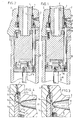
- figs. 1 and 2 corresponding sections through a portion of a mould for manufacturing a tubular body 1 are shown: fig. 1 show a position wherein the tubular body can be moulded such as by extrusion in the moulding cavity delimited by a devidable mould jacket 2, 3 and a core 4, and fig. 2 shows a position wherein the sealing ring 5 can be moulded. Details of these sections are shown at a larger scale in figs. 3 and 4 respectively.
- the extrusion mould shown only partly in the drawings is mainly formed by a core 4, surrounded by a moulding jacket which can be divided in an upper mould section 3 and a lower mould section 2. These parts are delimiting a moulding cavity wherein a tubular body 1 has been moulded by extrusion.
- a hydraulic or pneumatic cylinder unit (not shown) is energized such that a piston rod 7 thereof is moved in the direction as indicated by the arrow 8.
- the disk 9 being connected to the piston rod 7, the pulling rods 10 connected thereto and the supporting ring 11 being connected with the free ends of the pulling rods 10 and being coaxially slidable about the core 4 can be moved together with the piston rod in this manner.
- Pressurizing is done in the invented method by feeding thermoplastic deformable, elastomeric raw material for the sealing ring against the inner surface of the tubular body just across the site where the annular cavity 13 has been arranged. Then said material is brought in the desired shape and stabilized.
- thermoplastic deformable, elastomeric raw material for the sealing ring against the inner surface of the tubular body just across the site where the annular cavity 13 has been arranged. Then said material is brought in the desired shape and stabilized.
- Several elastomeric materials may be used as a raw material, provided these materials are thermoplastic deformable, such that plastic deformation and transport through the feeding system in the mould are possible and subsequent stabilisation in that shape is possible.
- annular section 14 is slidably in axial direction arranged about the core. In one position the inward face of said annular section 14 is abutting a corresponding face of the core, such that no space for plastic material for the tubular body is available. This condition is shown in fig. 3.
- annular moulding cavity 15 formed between said faces of the core and the annular section, its shape corresponding with that of the sealing ring 5 to be moulded.
- This moulding cavity is connected to a feeding channel 16, through which elastomeric raw material for the sealing ring may be extruded from a extrusion connection 17 to said cavity.
- the extrusion connection In the extrusion connection a nozzle of an extrusion apparatus can be inserted.
- the extrusion connection is preferably arranged in the moulding jacket near the sealing ring to be moulded and is the feeding channel extending through the annular element 12.
- the displacement of the annular section 14 also results from energizing the cilinder and so from moving the rods 10 relatively to the moulding jacket and the core. After a short axial displacement of the support ring 11, it abuts a second support ring 18 being also coaxially slidable about the core. Said second support ring is connected with the annular section 14 so that by further axial displacement of the rods 10 the support ring 11 and now the support ring 18 too and the annular section 14 are moved until the second support ring 18 abuts a stop 19 in the moulding shell and the position shown in figs. 2 and 4 is obtained.
- the inward groove in the tubular body is formed and also the sealing ring 5 is suitably moulded and arranged in said groove.
- the shape of said ring is.fixed or stabilized by cooling thereby solidi- fyring the material.
- a subsequent cross-linking may be arranged such as by radiation, but is mostly not necessary.
- the stabilized condition being obtained the tubular body having the sealing ring inserted may be removed from the mould in a usual manner. It is important that the internal diameter of the open end of the tubular body outward of the sealing ring is slightly in excess of the internal diameter beyond said ring for preventing damaging the sealing ring when removing the core from the tubular body.
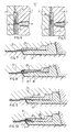
- FIG. 5 A simple embodiment to be used when the sealing ring needs only to extend by some millimetres inwardly is shown in figs. 5 and 6 showing sections of modified simple embodiments comparable with figs. 3 and 4.
- no separate moulding cavity is used for moulding the sealing ring but the core is provided with a shallow annular groove 20 where the ring is to be arranged. Said groove may be connected with the feeding channel 16.
- synthetic material is extruded into the moulding cavity for the tubular body 1, whereby the annular groove 20 is filled too.
- the feeding channel for raw material for the sealing ring extends from the extrusion connection to the annular groove 20 such that when extruding said raw material the still plastic deformable resin of the tubular body will be moved into the annular cavity 13 while forming an internal groove which is simultaneously filled with the sealing ring 22.
- Said ring only slightly extends inwardly and will not obstruct the removal of the core.
- the annular groove 20 is preferably provided with annular peripheral ridges for providing the ring with corresponding ridges. Shifting the key 21 obtained in the same manner as that of the annular section 14 by energizing a hydraulic or pneumatic cylinder for moving one or more support rings for said parts in the manner as shown in fig. 1 and 2 through the disc 9 and the rods 10.
- a partial section through a modified embodiment of a mould is shown in a similar manner as in figs. 3 and 4.
- the moulding cavity formed between the moulding jacket 23 and the annular element 24 being slidably arranged therein on the outside and the core 25 and an annular section 26 being slidably arranged thereon on the inside is cylindrical having a widened sleeve portion.
- the axial limit of the annular element 24 is positioned about halfway the sleeve portion of uniform diameter. This also applies to the annular section 26.
Landscapes
- Engineering & Computer Science (AREA)
- Manufacturing & Machinery (AREA)
- Mechanical Engineering (AREA)
- Shaping Of Tube Ends By Bending Or Straightening (AREA)
Priority Applications (3)
| Application Number | Priority Date | Filing Date | Title |
|---|---|---|---|
| EP80200277A EP0036454B1 (fr) | 1980-03-25 | 1980-03-25 | Procédé et dispositif pour fabriquer un corps tubulaire comprenant un anneau d'étanchéité |
| DE8080200277T DE3065652D1 (en) | 1980-03-25 | 1980-03-25 | Method and apparatus for manufacturing a tubular body provided with a sealing ring |
| AT80200277T ATE5386T1 (de) | 1980-03-25 | 1980-03-25 | Verfahren und vorrichtung zum herstellen eines rohrfoermigen koerpers mit einem dichtungsring. |
Applications Claiming Priority (1)
| Application Number | Priority Date | Filing Date | Title |
|---|---|---|---|
| EP80200277A EP0036454B1 (fr) | 1980-03-25 | 1980-03-25 | Procédé et dispositif pour fabriquer un corps tubulaire comprenant un anneau d'étanchéité |
Publications (2)
| Publication Number | Publication Date |
|---|---|
| EP0036454A1 true EP0036454A1 (fr) | 1981-09-30 |
| EP0036454B1 EP0036454B1 (fr) | 1983-11-23 |
Family
ID=8186980
Family Applications (1)
| Application Number | Title | Priority Date | Filing Date |
|---|---|---|---|
| EP80200277A Expired EP0036454B1 (fr) | 1980-03-25 | 1980-03-25 | Procédé et dispositif pour fabriquer un corps tubulaire comprenant un anneau d'étanchéité |
Country Status (3)
| Country | Link |
|---|---|
| EP (1) | EP0036454B1 (fr) |
| AT (1) | ATE5386T1 (fr) |
| DE (1) | DE3065652D1 (fr) |
Cited By (2)
| Publication number | Priority date | Publication date | Assignee | Title |
|---|---|---|---|---|
| US5057263A (en) * | 1987-10-29 | 1991-10-15 | Forsheda Ab | Method of forming a pipe socket |
| GB2325636A (en) * | 1997-05-31 | 1998-12-02 | Dalatek Ltd | Improvements in or relating to pipes |
Citations (8)
| Publication number | Priority date | Publication date | Assignee | Title |
|---|---|---|---|---|
| FR1578138A (fr) * | 1968-06-21 | 1969-08-14 | ||
| GB1236907A (en) * | 1969-02-25 | 1971-06-23 | Hepworth Iron Co Ltd | Improvements in or relating to pipe couplings |
| NL7408628A (en) * | 1974-06-26 | 1975-12-30 | Wavin Bv | Tube with grooved socket end prodn - by injection moulding tube with cylindrical end, and deforming cylindrical end in mould |
| AT339032B (de) * | 1974-07-29 | 1977-09-26 | Ifw Ind Formen Werkzeug | Mehrteilige spritzgussform |
| US4127632A (en) * | 1975-07-29 | 1978-11-28 | Anton Anger Maschinenbau Gmbh | Method of producing undercut tubular synthetic plastic articles |
| NL7809777A (nl) * | 1978-09-27 | 1980-03-31 | Hawo B V | Werkwijze en inrichting voor het vervaardigen van een buisstuk voorzien van een afdichtring. |
| NL7907705A (nl) * | 1978-10-18 | 1980-04-22 | Battenfeld Maschfab | Vervaardigingswerkwijze van fittings of dergelijke voor buisverbindingen, alsmede gereedschap voor het uitvoe- ren van die werkwijze en, met toepassing van die werkwijze vervaardigde fitting of dergelijke. |
| DE2845308A1 (de) * | 1978-10-18 | 1980-04-24 | Battenfeld Maschfab | Fitting o.dgl. aus formstabilem kunststoff fuer rohrverbindungen sowie verfahren und werkzeug zu seiner herstellung |
-
1980
- 1980-03-25 AT AT80200277T patent/ATE5386T1/de active
- 1980-03-25 EP EP80200277A patent/EP0036454B1/fr not_active Expired
- 1980-03-25 DE DE8080200277T patent/DE3065652D1/de not_active Expired
Patent Citations (10)
| Publication number | Priority date | Publication date | Assignee | Title |
|---|---|---|---|---|
| FR1578138A (fr) * | 1968-06-21 | 1969-08-14 | ||
| GB1236907A (en) * | 1969-02-25 | 1971-06-23 | Hepworth Iron Co Ltd | Improvements in or relating to pipe couplings |
| NL7408628A (en) * | 1974-06-26 | 1975-12-30 | Wavin Bv | Tube with grooved socket end prodn - by injection moulding tube with cylindrical end, and deforming cylindrical end in mould |
| AT339032B (de) * | 1974-07-29 | 1977-09-26 | Ifw Ind Formen Werkzeug | Mehrteilige spritzgussform |
| US4127632A (en) * | 1975-07-29 | 1978-11-28 | Anton Anger Maschinenbau Gmbh | Method of producing undercut tubular synthetic plastic articles |
| NL7809777A (nl) * | 1978-09-27 | 1980-03-31 | Hawo B V | Werkwijze en inrichting voor het vervaardigen van een buisstuk voorzien van een afdichtring. |
| NL7907705A (nl) * | 1978-10-18 | 1980-04-22 | Battenfeld Maschfab | Vervaardigingswerkwijze van fittings of dergelijke voor buisverbindingen, alsmede gereedschap voor het uitvoe- ren van die werkwijze en, met toepassing van die werkwijze vervaardigde fitting of dergelijke. |
| DE2845308A1 (de) * | 1978-10-18 | 1980-04-24 | Battenfeld Maschfab | Fitting o.dgl. aus formstabilem kunststoff fuer rohrverbindungen sowie verfahren und werkzeug zu seiner herstellung |
| FR2439077A1 (fr) * | 1978-10-18 | 1980-05-16 | Battenfeld Maschfab | Procede et outil de fabrication d'un raccord tubulaire en matiere synthetique, et raccord fabrique selon ce procede |
| GB2035192A (en) * | 1978-10-18 | 1980-06-18 | Battenfeld Maschfab | Method of producing pipe fittings with sealing rings |
Cited By (3)
| Publication number | Priority date | Publication date | Assignee | Title |
|---|---|---|---|---|
| US5057263A (en) * | 1987-10-29 | 1991-10-15 | Forsheda Ab | Method of forming a pipe socket |
| GB2325636A (en) * | 1997-05-31 | 1998-12-02 | Dalatek Ltd | Improvements in or relating to pipes |
| GB2325636B (en) * | 1997-05-31 | 2002-04-17 | Dalatek Ltd | Improvements in or relating to pipes |
Also Published As
| Publication number | Publication date |
|---|---|
| EP0036454B1 (fr) | 1983-11-23 |
| ATE5386T1 (de) | 1983-12-15 |
| DE3065652D1 (en) | 1983-12-29 |
Similar Documents
| Publication | Publication Date | Title |
|---|---|---|
| US5466141A (en) | Device for injection molding articles of plastics material which contain hollow spaces | |
| US4268237A (en) | Apparatus for manufacturing a tubular body provided with a sealing ring | |
| US3914101A (en) | Apparatus for forming corrugated tubing | |
| USRE27736E (en) | Method of shaping the end of a pipe of thermoplastic material into a bell | |
| US2826784A (en) | Plastic pipe molding apparatus | |
| FI74654B (fi) | Anordning och foerfarande foer framstaellning av kamflaensroer. | |
| JPH02223424A (ja) | 収縮自在コアを具備する成型装置 | |
| JP2001504048A (ja) | プラスチックチューブの製造方法および設備と、それによって得られるプラスチックチューブ | |
| US4397629A (en) | Apparatus for drawing mouth-neck portions of synthetic resin bottles | |
| US3705779A (en) | Device for manufacturing a plastic tube with transverse grooves | |
| US4150087A (en) | Tube of thermoplastics with thickened end | |
| US3564661A (en) | Flexible mandrels | |
| EP0036454A1 (fr) | Procédé et dispositif pour fabriquer un corps tubulaire comprenant un anneau d'étanchéité | |
| SU736865A3 (ru) | Способ изготовлени кольцевой канавки на пластмассовой трубе и устройство дл его осуществлени | |
| US2891581A (en) | Flexible hose and method of making the same | |
| US4614631A (en) | Process for screw-cutting in a tube or link made from a composite carbon fiber based material coated with polymerized resin | |
| US2457647A (en) | Method of making rubber articulated joints | |
| US2379508A (en) | Torsional joint | |
| IE49436B1 (en) | Method and apparatus for manufacturing a tubular body provided with a sealing ring | |
| US4015918A (en) | Hose molding device | |
| GB2145364A (en) | Releasing tubular article from mould | |
| US5405568A (en) | Two-piece segmented tire mold and method of molding | |
| US3986810A (en) | Method and apparatus for shaping a normally rigid plastic pipe | |
| JP3751376B2 (ja) | ホースの口金取付け方法および装置 | |
| US3729282A (en) | Apparatus for radially expanding the end portion of a tube mode of thermoplastic synthetic material |
Legal Events
| Date | Code | Title | Description |
|---|---|---|---|
| PUAI | Public reference made under article 153(3) epc to a published international application that has entered the european phase |
Free format text: ORIGINAL CODE: 0009012 |
|
| 17P | Request for examination filed |
Effective date: 19810416 |
|
| AK | Designated contracting states |
Designated state(s): AT BE DE FR GB NL SE |
|
| GRAA | (expected) grant |
Free format text: ORIGINAL CODE: 0009210 |
|
| AK | Designated contracting states |
Designated state(s): AT BE DE FR GB NL SE |
|
| REF | Corresponds to: |
Ref document number: 5386 Country of ref document: AT Date of ref document: 19831215 Kind code of ref document: T |
|
| REF | Corresponds to: |
Ref document number: 3065652 Country of ref document: DE Date of ref document: 19831229 |
|
| ET | Fr: translation filed | ||
| PGFP | Annual fee paid to national office [announced via postgrant information from national office to epo] |
Ref country code: DE Payment date: 19840410 Year of fee payment: 5 |
|
| PGFP | Annual fee paid to national office [announced via postgrant information from national office to epo] |
Ref country code: FR Payment date: 19840412 Year of fee payment: 5 |
|
| PGFP | Annual fee paid to national office [announced via postgrant information from national office to epo] |
Ref country code: SE Payment date: 19840630 Year of fee payment: 5 Ref country code: BE Payment date: 19840630 Year of fee payment: 5 |
|
| PLBE | No opposition filed within time limit |
Free format text: ORIGINAL CODE: 0009261 |
|
| STAA | Information on the status of an ep patent application or granted ep patent |
Free format text: STATUS: NO OPPOSITION FILED WITHIN TIME LIMIT |
|
| 26N | No opposition filed | ||
| PGFP | Annual fee paid to national office [announced via postgrant information from national office to epo] |
Ref country code: AT Payment date: 19870316 Year of fee payment: 8 |
|
| PGFP | Annual fee paid to national office [announced via postgrant information from national office to epo] |
Ref country code: NL Payment date: 19870331 Year of fee payment: 8 |
|
| PG25 | Lapsed in a contracting state [announced via postgrant information from national office to epo] |
Ref country code: AT Effective date: 19880325 |
|
| PG25 | Lapsed in a contracting state [announced via postgrant information from national office to epo] |
Ref country code: SE Effective date: 19880326 |
|
| BERE | Be: lapsed |
Owner name: HAWO B.V. Effective date: 19880331 |
|
| PG25 | Lapsed in a contracting state [announced via postgrant information from national office to epo] |
Ref country code: NL Effective date: 19881001 |
|
| NLV4 | Nl: lapsed or anulled due to non-payment of the annual fee | ||
| PG25 | Lapsed in a contracting state [announced via postgrant information from national office to epo] |
Ref country code: GB Free format text: LAPSE BECAUSE OF NON-PAYMENT OF DUE FEES Effective date: 19881118 |
|
| GBPC | Gb: european patent ceased through non-payment of renewal fee | ||
| PG25 | Lapsed in a contracting state [announced via postgrant information from national office to epo] |
Ref country code: FR Free format text: LAPSE BECAUSE OF NON-PAYMENT OF DUE FEES Effective date: 19881130 |
|
| PG25 | Lapsed in a contracting state [announced via postgrant information from national office to epo] |
Ref country code: DE Effective date: 19881201 |
|
| REG | Reference to a national code |
Ref country code: FR Ref legal event code: ST |
|
| PG25 | Lapsed in a contracting state [announced via postgrant information from national office to epo] |
Ref country code: BE Effective date: 19890331 |
|
| EUG | Se: european patent has lapsed |
Ref document number: 80200277.4 Effective date: 19881205 |