EP0041124B1 - Gelenk für Führungssäulen an Werkzeugwagen - Google Patents
Gelenk für Führungssäulen an Werkzeugwagen Download PDFInfo
- Publication number
- EP0041124B1 EP0041124B1 EP81103033A EP81103033A EP0041124B1 EP 0041124 B1 EP0041124 B1 EP 0041124B1 EP 81103033 A EP81103033 A EP 81103033A EP 81103033 A EP81103033 A EP 81103033A EP 0041124 B1 EP0041124 B1 EP 0041124B1
- Authority
- EP
- European Patent Office
- Prior art keywords
- joint
- guide tube
- column
- another
- tool cart
- Prior art date
- Legal status (The legal status is an assumption and is not a legal conclusion. Google has not performed a legal analysis and makes no representation as to the accuracy of the status listed.)
- Expired
Links
- 230000007246 mechanism Effects 0.000 claims abstract description 3
- 239000011324 bead Substances 0.000 description 3
- 230000002349 favourable effect Effects 0.000 description 1
- 239000012535 impurity Substances 0.000 description 1
- 238000004519 manufacturing process Methods 0.000 description 1
Images

Classifications
-
- F—MECHANICAL ENGINEERING; LIGHTING; HEATING; WEAPONS; BLASTING
- F16—ENGINEERING ELEMENTS AND UNITS; GENERAL MEASURES FOR PRODUCING AND MAINTAINING EFFECTIVE FUNCTIONING OF MACHINES OR INSTALLATIONS; THERMAL INSULATION IN GENERAL
- F16C—SHAFTS; FLEXIBLE SHAFTS; ELEMENTS OR CRANKSHAFT MECHANISMS; ROTARY BODIES OTHER THAN GEARING ELEMENTS; BEARINGS
- F16C11/00—Pivots; Pivotal connections
- F16C11/04—Pivotal connections
-
- B—PERFORMING OPERATIONS; TRANSPORTING
- B25—HAND TOOLS; PORTABLE POWER-DRIVEN TOOLS; MANIPULATORS
- B25H—WORKSHOP EQUIPMENT, e.g. FOR MARKING-OUT WORK; STORAGE MEANS FOR WORKSHOPS
- B25H3/00—Storage means or arrangements for workshops facilitating access to, or handling of, work tools or instruments
- B25H3/02—Boxes
- B25H3/021—Boxes comprising a number of connected storage elements
- B25H3/023—Boxes comprising a number of connected storage elements movable relative to one another for access to their interiors
- B25H3/026—Boxes comprising a number of connected storage elements movable relative to one another for access to their interiors by displacement in a direction substantially perpendicated to th base
Definitions
- the invention relates to a joint for guide columns on tool trolleys, which have at least one intermediate floor and a cover, which are mounted on two guide columns in a height-adjustable manner between a closed position and a use position, the guide columns in the closed position of the tool trolley by means of their joint are pivotable about 90 ° into a position running parallel to the cover.
- the joint known from DE-B-2 427 283 for folding the guide columns consists of a bearing bolt arranged transversely to the column, which penetrates both parts of the fixed column piece and the foldable column piece. Since the cross-section of the guide columns is relatively small, this known type of joint results in small bearing surfaces which wear out quickly under high loads and give rise to faults. Since tool trolleys filled with workpieces and tools are also transported by means of the handle, very high stresses on the known joints occur regularly.
- the invention has for its object to provide a hinge for guide columns on tool trolleys of the type presupposed as known, which allows the guide columns to be flipped over with the simplest design and high functional reliability, without impurities being able to hinder the function.
- the joint consists, in a manner known per se, of two joint halves which abut one another with contact surfaces running at an angle of 45 ° to the longitudinal axis of the joint, relative to a bolt arranged at right angles to the contact surfaces are rotatable relative to one another and of which the lower joint half is inserted into a standpipe attached to the tool trolley and the upper joint half is inserted into the pivotable guide tube of the guide columns, and that an externally axially adjustable push rod is arranged in the guide tube of the guide columns, which is in each of the two end positions the guide tube locks the two joint halves.
- a joint consisting of two joint halves is already known from AT-B-151 858, in which the joint halves abut one another on an inclined contact surface and can be rotated relative to one another by a bolt which is arranged at right angles to the contact surfaces;
- this joint is not used for a tool trolley, nor is it locked in its two end positions in the manner according to the invention by a push rod which is arranged axially displaceably in one of the two tubes connected by the joint.
- the pivotable guide column known from DE-B-2427283 also has no locking element for the joint.
- the proposal according to the invention results in a joint with large bearing surfaces that can also withstand high loads.
- the joint is simple and inexpensive to manufacture and easy to assemble.
- the joint can thus also withstand high loads when used on mobile tool trolleys if a tool trolley filled with tools or workpieces is carried by means of the folded-over guide columns, the total weight having to be absorbed by the two joints.
- Due to the axially adjustable push rods a locking of the two joint halves is effected in each of the two end positions of the joints, which in particular prevents the guide columns from being accidentally bent or straightened up by the joints formed in them.
- the locking takes place here by means of simple mechanical components in both end positions of the joint.
- a particularly favorable locking option according to the invention results from the fact that a pressure piece is arranged in the upper joint half parallel to the bolt, which can be snapped into a recess in the lower joint half by the axial adjustment of the push rod in the end positions.
- the push rod can be axially adjustable by means of a thread in the upper half of the joint and can be provided at its free end with a turning handle which facilitates the actuation of the push rod.
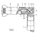
- the joint shown in an exemplary embodiment in FIGS. 1 and 2 is attached to a standpipe 1. It projects with a lower joint half 2 into this standpipe 1 and is held on the protruding part by beads 1a which engage in grooves, both in the longitudinal direction and in the circumferential direction of the standpipe 1.
- the lower joint half 2 has a contact surface 2a running at 45 ° to the longitudinal axis 5 of the standpipe 1.
- a contact surface 3a of an upper joint half 3 bears against this contact surface 2a, which in turn is fastened to a foldable guide tube 6 by beads 6a.
- connection of the two joint halves 2 and 3 is carried out by a bolt 4, which is arranged at right angles to the contact surfaces 2a and 3a, so that the upper joint half 3 is rotatably mounted on the joint half 2 with the guide tube 6 about the bolt longitudinal axis 4a. 1 and 2, the longitudinal axis 4a of the bolt intersects the longitudinal axis 5 of the standpipe 1 or the foldable guide tube 6 in the plane of the contact surface 2a and 3a.
- the guide tube 6 can be brought from the extended position shown in FIG. 1, in which it represents an extension of the standpipe 1, into a position shown in FIG. 2, in which it extends at right angles to the standpipe 1.
- the transfer into this position does not take place by folding in one plane, but by a rotational movement about the longitudinal axis 4a of the bolt, as is indicated in FIG. 5.
- two recesses 2b are arranged in the lower joint half 2, into which a pressure piece 9 which can be actuated by a push rod 7 by means of a rotary handle 8 engages.
- This pressure piece 9 is moved by the tip 7b of the pressure rod 7 in its axial direction when the pressure rod 7 is axially displaced by means of the rotary handle 8, namely in that the pressure rod 7 provided with a thread 7a in a threaded bore 3b of the upper joint half 3 is twisted.
- 1 shows how the pressure piece 9 engages in the extended position of the joint in the upper recess 2b of the lower joint half 2 and is held in this engagement position by the tip 7b of the pressure rod 7.
- Fig. 2 it can be seen that in the folded position of the guide tube 6, the pressure piece 9 engages in the lower recess 2b.
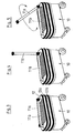
- the tool trolley 10 shown schematically in FIGS. 3 to 5 is provided with two guide columns 11a and 11b, the lower parts of which correspond to the standpipe 1 and are fastened to the box-shaped bottom of the tool trolley 10.
- a cover 12 and two intermediate floors 13a and 13b are slidably guided on the guide columns 11a and 11b, specifically when the guide columns 11a and 11b b are in their extended position. In this position of the guide columns 11a and 11b, not shown in the drawing, the cover 12 and the intermediate floors 13a and 13b can be raised.
- the cover 12 is locked in the uppermost position on the guide columns 11a and 11b, so that both the intermediate floors 13a and 13b and the box-shaped bottom of the tool carriage 11 are accessible from all sides.
- cover 12 and the intermediate floors 13a and 13b are in the lowered closed position according to FIG. 3, they can be located according to FIG. 3, the upper parts of the guide columns 11a and 2 corresponding to the foldable guide tube 6 in FIGS. 1 and 2 11b are folded parallel to the cover 12. In this position according to FIG. 3, the folded-over guide columns 11a and 11b serve as a carrying handle for the tool trolley 10.
- FIG. 5 shows that the folding over or erection of a guide column 11a takes place by means of a rotational movement, which is indicated in FIG. 5 by a double arrow. It is of course possible to use suitable locking mechanisms to ensure that the guide columns 11a and 11b folded over according to FIG. 3 cannot be erected, unless the lock has been lifted using the key provided for this purpose.
Landscapes
- Engineering & Computer Science (AREA)
- Mechanical Engineering (AREA)
- General Engineering & Computer Science (AREA)
- Conveying And Assembling Of Building Elements In Situ (AREA)
- Mutual Connection Of Rods And Tubes (AREA)
- Pivots And Pivotal Connections (AREA)
- Workshop Equipment, Work Benches, Supports, Or Storage Means (AREA)
- Handcart (AREA)
- Fishing Rods (AREA)
- Road Signs Or Road Markings (AREA)
Description
- Die Erfindung betrifft ein Gelenk für Führungssäulen an Werkzeugwagen, die mindestens einen Zwischenboden und einen Deckel besitzen, welche an zwei Führungssäulen zwischen einer aufeinander liegenden Schließstellung und einer Gebrauchsstellung in der Höhe verschiebbar gelagert sind, wobei die Führungssäulen in der Schließstellung des Werkzeugwagens mittels ihres Gelenkes um etwa 90° in eine parallel zum Deckel verlaufende Lage verschwenkbar sind.
- Ein derartiges Gelenk für Führungssäulen an Werkzeugwagen ist aus der DE-B-2 427 283 bekannt. Durch die verschwenkbare Ausführung der Führungssäulen bilden diese in der Schließstellung des Werkzeugwagens einen Traggriff, der gleichzeitig den Werkzeugwagen gegen ein Öffnen sichert, da in der verschwenkten Lage der Führungssäulen der Deckel und die Zwischenböden nicht aus ihrer aufeinander liegenden Schließstellung herausbewegt werden können.
- Das aus der DE-B-2 427 283 bekannte Gelenk zum Umlegen der Führungssäulen besteht aus einem quer zur Säule angeordneten Lagerbolzen, der sowohl Teile des festen Säulenstückes als auch des umlegbaren Säulenstückes durchdringt. Da der Querschnitt der Führungssäulen verhältnismäßig klein ist, ergeben sich bei dieser bekannten Bauart des Gelenks kleine Lagerflächen, die bei einer hohen Beanspruchung schnell verschleißen und zu Störungen Anlaß geben. Da auch mit Werkstücken und Werkzeugen gefüllte Werkzeugwagen mittels des Handgriffes transportiert werden, treten regelmäßig sehr hohe Beanspruchungen der bekannten Gelenke auf.
- Der Erfindung liegt die Aufgabe zugrunde, ein Gelenk für Führungssäulen an Werkzeugwagen der als bekannt vorausgesetzten Art zu schaffen, das bei einfachster Bauart und hoher Funktionssicherheit ein Umlegen der Führungssäulen ermöglicht, ohne daß Verunreinigungen die Funktion behindern können.
- Die Lösung dieser Aufgabenstellung durch die Erfindung ist dadurch gekennzeichnet, daß das Gelenk in an sich bekannter Weise aus zwei Gelenkhälften besteht, die mit unter einem Winkel von 45° zur Längsachse des Gelenks verlaufenden Berührungsflächen aneinander anliegen, um einen rechtwinklig zu den Berührungsflächen angeordneten Bolzen relativ zueinander verdrehbar sind und von denen die untere Gelenkhälfte in ein am Werkzeugwagen befestigtes Standrohr und die obere Gelenkhälfte in das verschwenkbare Führungsrohr der Führungssäulen eingesetzt ist, und daß in dem Führungsrohr der Führungssäulen eine von außen axial verstellbare Druckstange angeordnet ist, die in jeder der beiden Endstellungen des Führungsrohres eine Verriegelung der beiden Gelenkhälften bewirkt.
- Aus der AT-B-151 858 ist zwar bereits ein aus zwei Gelenkhälften bestehendes Gelenk bekannt, bei dem die Gelenkhälften auf einer schräg liegenden Berührungsfläche aneinander anliegen und um einen Bolzen relativ zueinander verdrehbar sind, der rechtwinklig zu den Berührungsflächen angeordnet ist; dieses Gelenk wird jedoch weder für einen Werkzeugwagen verwendet, noch in seinen beiden Endstellungen in der erfindungsgemäßen Weise durch eine Druckstange verriegelt, die in einem der beiden durch das Gelenk miteinander verbundenen Rohre axial verschiebbar angeordnet ist. Auch die aus der DE-B-2427283 bekannte, verschwenkbare Führungssäule besitzt kein Verriegelungselement für das Gelenk.
- Der erfindungsgemäße Vorschlag ergibt ein Gelenk mit großen Lagerflächen, die auch hohen Belastungen gewachsen sind. Ausserdem ist das Gelenk einfach und preiswert herstellbar und leicht zu montieren. Das Gelenk kann somit bei seinem Einsatz an fahrbaren Werkzeugwagen auch hohe Belastungen aufnehmen, wenn ein mit Werkzeug oder Werkstücken gefüllter Werkzeugwagen mittels der umgelegten Führungssäulen getragen wird, wobei das Gesamtgewicht von den beiden Gelenken aufgenommen werden muß. Durch die von außen axial verstellbaren Druckstangen wird in jeder der beiden Endstellungen der Gelenke eine Verriegelung der beiden Gelenkhälften bewirkt, die insbesondere verhindert, daß die Führungssäulen durch die in ihnen ausgebildeten Gelenke ungewollt abknicken bzw. sich aufrichten. Die Verriegelung erfolgt hierbei mittels einfacher mechanischer Bauteile in beiden Endstellungen des Gelenkes.
- Eine besonders günstige Verriegelungsmöglichkeit ergibt sich erfindungsgemäß dadurch, daß in der oberen Gelenkhälfte parallel zum Bolzen ein Druckstück angeordnet ist, das durch die axiale Verstellung der Druckstange in den Endstellungen jeweils in eine Ausnehmung der unteren Gelenkhälfte einrastbar ist. Die Druckstange kann mittels eines Gewindes in der oberen Gelenkhälfte axial verstellbar und an ihrem freien Ende mit einem Drehgriff versehen sein, der die Betätigung der Druckstange erleichtert.
- Auf der Zeichnung ist ein Ausführungsbeispiel des erfindungsgemäßen Gelenks dargestellt, und zwar zeigen :
- Figur 1 einen Längsschnitt durch ein in einer Führungssäule eingebautes Gelenk in der gestreckten Stellung, (Es folgt jetzt der restliche Text der Figurenaufzählung und die Figuren beschreibung auf den Seiten 5-7 der ursprünglichen Anmeldungsunterlagen).
- Figur 2 einen der Fig. 1 entsprechenden Längsschnitt in der umgelegten Stellung,
- Figur 3 eine perspektivische Ansicht eines fahrbaren Werkzeugwagens mit umgelegten Führungssäulen,
- Figur 4 eine der Fig. 3 entsprechende Darstellung mit einer aufgerichteten Führungssäule und
- Figur 5 eine Darstellung gemäß den Fig. 3 und 4 während des Umlegens einer der beiden Führungssäulen.
- Das anhand eines Ausführungsbeispiel in den Fig. 1 und 2 dargestellte Gelenk ist an einem Standrohr 1 befestigt. Es ragt mit einer unteren Gelenkhälfte 2 in dieses Standrohr 1 hinein und ist am hineinragenden Teil durch in Nuten eingreifende Sicken 1a sowohl in Längsrichtung als auch in Umfangsrichtung des Standrohres 1 festgehalten. Die untere Gelenkhälfte 2 besitzt eine unter 45° zur Längsachse 5 des Standrohres 1 verlaufende Berührungsfläche 2a. An dieser Berührungsfläche 2a liegt eine Berührungsfläche 3a einer oberen Gelenkhälfte 3 an, die ihrerseits an einem umlegbaren Führungsrohr 6 durch Sicken 6a befestigt ist.
- Die Verbindung der beiden Gelenkhälften 2 und 3 erfolgt durch einen Bolzen 4, der rechtwinklig zu den Berührungsflächen 2a und 3a angeordnet ist, so daß die obere Gelenkhälfte 3 mit dem Führungsrohr 6 um die Bolzenlängsachse 4a verdrehbar an der Gelenkhälfte 2 gelagert ist. Wie die Darstellungen in Fig. 1 und 2 erkennen lassen, schneidet die Bolzenlängsachse 4a die Längsachse 5 des Standrohres 1 bzw. umlegbaren Führungsrohres 6 in der Ebene der Berührungsfläche 2a und 3a.
- Aufgrund des voranstehend beschriebenen Gelenks kann das Führungsrohr 6 aus der in Fig. 1 dargestellten gestreckten Lage, in der es eine Verlängerung des Standrohres 1 darstellt, in eine in Fig. 2 dargestellte Lage gebracht werden, in der es rechtwinklig zum Standrohr 1 verläuft. Die Überführung in diese Stellung geschieht nicht durch Umlegen in einer Ebene, sondern durch eine Rotationsbewegung um die Bolzenlängsachse 4a, wie dies in Fig. 5 angedeutet ist.
- Um die beiden Gelenkhälften 2 und 3 in den beiden Endstellungen arretieren zu können, sind in der unteren Gelenkhälfte 2 zwei Ausnehmungen 2b angeordnet, in die ein durch eine Druckstange 7 mittels eines Drehgriffes 8 betätigbares Druckstück 9 eingreift. Dieses Druckstück 9 wird durch die Spitze 7b der Druckstange 7 in seiner axialen Richtung bewegt, wenn die Druckstange 7 mittels des Drehgriffes 8 axial verlagert wird, und zwar dadurch, daß die mit einem Gewinde 7a versehene Druckstange 7 in einer Gewindebohrung 3b der oberen Gelenkhälfte 3 verdreht wird. Die Fig. 1 zeigt, wie das Druckstück 9 in der gestreckten Stellung des Gelenkes in die obere Ausnehmung 2b der unteren Gelenkhälfte 2 eingreift und in dieser Eingreifstellung durch die Spitze 7b der Druckstange 7 gehalten wird. In Fig. 2 ist zu erkennen, daß in der umgelegten Stellung des Führungsrohres 6 das Druckstück 9 in die untere Ausnehmung 2b eingreift.
- Der in den Fig. 3 bis 5 schematisch dargestellte Werkzeugwagen 10 ist mit zwei Führungssäulen 11a und 11b versehen, deren untere Teile dem Standrohr 1 entsprechen und am kastenförmigen Boden des Werkzeugwagens 10 befestigt sind. An den Führungssäulen 11a und 11b sind ein Deckel 12 sowie zwei Zwischenböden 13a und 13b verschiebbar geführt, und zwar wenn sich die Führungssäulen 11a und 11b b in ihrer gestreckten Lage befinden. In dieser auf der Zeichnung nicht dargestellten Lage der Führungssäulen 11a und 11b können der Deckel 12 und die Zwischenböden 13a und 13b angehoben werden. Der Deckel 12 wird in der obersten Stellung an den Führungssäulen 11a und 11b arretiert, so daß sowohl die Zwischenböden 13a und 13b als auch der kastenförmige Boden des Werkzeugwagens 11 von allen Seiten zugänglich sind.
- Wenn sich der Deckel 12 und die Zwischenböden 13a und 13b in der abgesenkten Schließstellung gemäß Fig. 3 befinden, können die dem lung gemäß Fig. 3 befinden, können die dem umlegbaren Führungsrohr 6 in den Fig. 1 und 2 entsprechenden Oberteile der Führungssäulen 11a und 11b parallel zum Deckel 12 umgelegt werden. In dieser Stellung gemäß Fig. 3 dienen die umgelegten Führungssäulen 11a und 11b als Traggriff für den Werkzeugwagen 10.
- Die Fig. 5 zeigt schließlich, daß das Umlegen bzw. Aufrichten einer Führungssäule 11a durch eine Rotationsbewegung erfolgt, die in Fig. 5 durch einen Doppelpfeil angedeutet wird. Selbstverständlich ist es möglich, durch geeignete Verschlußmechanismen dafür zu sorgen, daß die gemäß Fig. 3 umgelegten Führungssäulen 11a und 11b nicht aufgerichtet werden können, sofern nicht eine Aufhebung des Verschlusses mittels des hierfür vorgesehenen Schlüssels erfolgt ist.
-
- 1 Standrohr
- 1a Sicke
- 2 Untere Gelenkhälfte
- 2a Berührungsfläche
- 2b Ausnehmung
- 3 Obere Gelenkhälfte
- 3a Berührungsfläche
- 3b Gewindebohrung
- 4 Bolzen
- 4a Bolzenlängsachse
- 5 Längsachse
- 6 Führungsrohr
- 7 Druckstange
- 7a Gewinde
- 7b Spitze
- 8 Drehgriff
- 9 Druckstück
- 10 Werkzeugwagen
- 11a Führungssäule
- 11 b Führungssäule
- 12 Deckel
- 13a Zwischenboden
- 13b Zwischenboden
Claims (3)
Priority Applications (1)
| Application Number | Priority Date | Filing Date | Title |
|---|---|---|---|
| AT81103033T ATE7950T1 (de) | 1980-06-03 | 1981-04-22 | Gelenk fuer fuehrungssaeulen an werkzeugwagen. |
Applications Claiming Priority (2)
| Application Number | Priority Date | Filing Date | Title |
|---|---|---|---|
| DE3020946 | 1980-06-03 | ||
| DE3020946A DE3020946A1 (de) | 1980-06-03 | 1980-06-03 | Gelenk |
Publications (2)
| Publication Number | Publication Date |
|---|---|
| EP0041124A1 EP0041124A1 (de) | 1981-12-09 |
| EP0041124B1 true EP0041124B1 (de) | 1984-06-13 |
Family
ID=6103807
Family Applications (1)
| Application Number | Title | Priority Date | Filing Date |
|---|---|---|---|
| EP81103033A Expired EP0041124B1 (de) | 1980-06-03 | 1981-04-22 | Gelenk für Führungssäulen an Werkzeugwagen |
Country Status (4)
| Country | Link |
|---|---|
| EP (1) | EP0041124B1 (de) |
| JP (1) | JPS6029007B2 (de) |
| AT (1) | ATE7950T1 (de) |
| DE (2) | DE3020946A1 (de) |
Families Citing this family (1)
| Publication number | Priority date | Publication date | Assignee | Title |
|---|---|---|---|---|
| DE102005060268A1 (de) * | 2005-12-13 | 2007-06-21 | Burg Giebichenstein Hochschule für Kunst und Design | Bewegliches Verbindungselement für Möbel und Raumausstattungen |
Citations (1)
| Publication number | Priority date | Publication date | Assignee | Title |
|---|---|---|---|---|
| DE2427283B2 (de) * | 1974-04-29 | 1977-02-10 | Bächli, Emil, Endingen (Schweiz) | Mehrteiliger aufbewahrungsbehaelter fuer werkzeuge und kleinmaterialien |
Family Cites Families (3)
| Publication number | Priority date | Publication date | Assignee | Title |
|---|---|---|---|---|
| DE8014771U1 (de) * | 1980-08-28 | Hazet-Werk Hermann Zerver Gmbh & Co Kg, 5630 Remscheid | Gelenk | |
| AT151858B (de) * | 1936-11-03 | 1937-12-10 | Josef Heitmanek | Verbindungsgelenk, insbesondere für stab- oder rohrförmige Teile. |
| DE1290900B (de) * | 1966-09-06 | 1969-03-13 | Hazet Werk Zerver Hermann | Werkzeugwagen, insbesondere fuer Reparaturwerkstaetten |
-
1980
- 1980-06-03 DE DE3020946A patent/DE3020946A1/de not_active Withdrawn
-
1981
- 1981-04-22 DE DE8181103033T patent/DE3164123D1/de not_active Expired
- 1981-04-22 AT AT81103033T patent/ATE7950T1/de not_active IP Right Cessation
- 1981-04-22 EP EP81103033A patent/EP0041124B1/de not_active Expired
- 1981-05-20 JP JP56075078A patent/JPS6029007B2/ja not_active Expired
Patent Citations (1)
| Publication number | Priority date | Publication date | Assignee | Title |
|---|---|---|---|---|
| DE2427283B2 (de) * | 1974-04-29 | 1977-02-10 | Bächli, Emil, Endingen (Schweiz) | Mehrteiliger aufbewahrungsbehaelter fuer werkzeuge und kleinmaterialien |
Also Published As
| Publication number | Publication date |
|---|---|
| DE3020946A1 (de) | 1981-12-10 |
| DE3164123D1 (en) | 1984-07-19 |
| JPS6029007B2 (ja) | 1985-07-08 |
| ATE7950T1 (de) | 1984-06-15 |
| JPS5722413A (en) | 1982-02-05 |
| EP0041124A1 (de) | 1981-12-09 |
Similar Documents
| Publication | Publication Date | Title |
|---|---|---|
| DE2306478A1 (de) | Vorrichtung zum veraendern von hoehenlage und laengsneigung der sitzflaeche von sitzen | |
| DE3230256C2 (de) | Vorrichtung zum Lenken eines mindestens ein Vorderrad und mindestens ein Hinterrad aufweisenden Fahrzeugs | |
| DE1778196C3 (de) | Hubvorrichtung für ein Sitzmöbel | |
| DE3309174C1 (de) | Bettseitenteil | |
| EP0041124B1 (de) | Gelenk für Führungssäulen an Werkzeugwagen | |
| DE2004504C3 (de) | Längsverstelleinrichtung für Fahrzeugsitze | |
| DE2727655A1 (de) | Kontinuierlich abstuetzender, beweglicher stuetz- oder grubenstempel | |
| DE9214601U1 (de) | Verfahrbares Wandelement für eine Trennwand | |
| EP0539891B1 (de) | Schwenktür für Container | |
| DE10328309B4 (de) | Klappgelenk mit Innenverriegelung | |
| EP3892494B1 (de) | Fahrgasttisch | |
| DE20109549U1 (de) | Tischtennisplatte | |
| DE2702144A1 (de) | Betaetigungsvorrichtung fuer zwei hydraulische ventile | |
| WO1989001910A1 (fr) | Systeme de guidage pour le guidage force d'elements mobiles l'un par rapport a l'autre | |
| DE19947188C2 (de) | Ausziehtisch mit einem Tischgestell | |
| DE2248373A1 (de) | Frachtcontainer | |
| DE3418252C2 (de) | Kippbarer Ständer zur Halterung eines Friseurgerätes | |
| DE2206681B2 (de) | Verriegelbares Gelenk | |
| CH661562A5 (de) | Bohrstangenfuehrung fuer eine bohrmaschine. | |
| CH622854A5 (en) | Setting-out device on wings or the like of windows or doors | |
| DE8014771U1 (de) | Gelenk | |
| EP0026364B1 (de) | Lagergestell zur Aufnahme von sich in Längsrichtung erstreckenden Brennelementen | |
| DE3248498A1 (de) | Vorrichtung zum arretieren von sektionalverschluessen | |
| DE2017202A1 (de) | Türfeststeller, insbesondere fur Kraftwagenturen | |
| DE1684096C3 (de) | Einschiebbare Bodentreppe |
Legal Events
| Date | Code | Title | Description |
|---|---|---|---|
| PUAI | Public reference made under article 153(3) epc to a published international application that has entered the european phase |
Free format text: ORIGINAL CODE: 0009012 |
|
| AK | Designated contracting states |
Designated state(s): AT BE CH DE FR GB IT NL SE |
|
| 17P | Request for examination filed |
Effective date: 19811210 |
|
| ITF | It: translation for a ep patent filed | ||
| GRAA | (expected) grant |
Free format text: ORIGINAL CODE: 0009210 |
|
| AK | Designated contracting states |
Designated state(s): AT BE CH DE FR GB IT LI NL SE |
|
| REF | Corresponds to: |
Ref document number: 7950 Country of ref document: AT Date of ref document: 19840615 Kind code of ref document: T |
|
| REF | Corresponds to: |
Ref document number: 3164123 Country of ref document: DE Date of ref document: 19840719 |
|
| ET | Fr: translation filed | ||
| PLBE | No opposition filed within time limit |
Free format text: ORIGINAL CODE: 0009261 |
|
| STAA | Information on the status of an ep patent application or granted ep patent |
Free format text: STATUS: NO OPPOSITION FILED WITHIN TIME LIMIT |
|
| 26N | No opposition filed | ||
| ITTA | It: last paid annual fee | ||
| EAL | Se: european patent in force in sweden |
Ref document number: 81103033.7 |
|
| PGFP | Annual fee paid to national office [announced via postgrant information from national office to epo] |
Ref country code: GB Payment date: 20000313 Year of fee payment: 20 |
|
| PGFP | Annual fee paid to national office [announced via postgrant information from national office to epo] |
Ref country code: SE Payment date: 20000320 Year of fee payment: 20 Ref country code: NL Payment date: 20000320 Year of fee payment: 20 |
|
| PGFP | Annual fee paid to national office [announced via postgrant information from national office to epo] |
Ref country code: AT Payment date: 20000322 Year of fee payment: 20 |
|
| PGFP | Annual fee paid to national office [announced via postgrant information from national office to epo] |
Ref country code: CH Payment date: 20000323 Year of fee payment: 20 |
|
| PGFP | Annual fee paid to national office [announced via postgrant information from national office to epo] |
Ref country code: BE Payment date: 20000405 Year of fee payment: 20 |
|
| PGFP | Annual fee paid to national office [announced via postgrant information from national office to epo] |
Ref country code: FR Payment date: 20000428 Year of fee payment: 20 |
|
| PGFP | Annual fee paid to national office [announced via postgrant information from national office to epo] |
Ref country code: DE Payment date: 20000623 Year of fee payment: 20 |
|
| BE20 | Be: patent expired |
Free format text: 20010422 HAZET-WERK HERMANN *ZERVER G.M.B.H. & CO. K.G. |
|
| PG25 | Lapsed in a contracting state [announced via postgrant information from national office to epo] |
Ref country code: LI Free format text: LAPSE BECAUSE OF EXPIRATION OF PROTECTION Effective date: 20010421 Ref country code: GB Free format text: LAPSE BECAUSE OF EXPIRATION OF PROTECTION Effective date: 20010421 Ref country code: CH Free format text: LAPSE BECAUSE OF EXPIRATION OF PROTECTION Effective date: 20010421 |
|
| PG25 | Lapsed in a contracting state [announced via postgrant information from national office to epo] |
Ref country code: NL Free format text: LAPSE BECAUSE OF EXPIRATION OF PROTECTION Effective date: 20010422 Ref country code: AT Free format text: LAPSE BECAUSE OF EXPIRATION OF PROTECTION Effective date: 20010422 |
|
| PG25 | Lapsed in a contracting state [announced via postgrant information from national office to epo] |
Ref country code: SE Free format text: THE PATENT HAS BEEN ANNULLED BY A DECISION OF A NATIONAL AUTHORITY Effective date: 20010429 |
|
| REG | Reference to a national code |
Ref country code: CH Ref legal event code: PL |
|
| REG | Reference to a national code |
Ref country code: GB Ref legal event code: PE20 Effective date: 20010421 |
|
| NLV7 | Nl: ceased due to reaching the maximum lifetime of a patent |
Effective date: 20010422 |
|
| EUG | Se: european patent has lapsed |
Ref document number: 81103033.7 |