EP0041137A1 - Mécanisme d'entraînement pour supports d'enregistrement en forme de disque - Google Patents
Mécanisme d'entraînement pour supports d'enregistrement en forme de disque Download PDFInfo
- Publication number
- EP0041137A1 EP0041137A1 EP81103428A EP81103428A EP0041137A1 EP 0041137 A1 EP0041137 A1 EP 0041137A1 EP 81103428 A EP81103428 A EP 81103428A EP 81103428 A EP81103428 A EP 81103428A EP 0041137 A1 EP0041137 A1 EP 0041137A1
- Authority
- EP
- European Patent Office
- Prior art keywords
- cone
- clamping
- spring element
- hollow cone
- spring
- Prior art date
- Legal status (The legal status is an assumption and is not a legal conclusion. Google has not performed a legal analysis and makes no representation as to the accuracy of the status listed.)
- Granted
Links
Images


Classifications
-
- G—PHYSICS
- G11—INFORMATION STORAGE
- G11B—INFORMATION STORAGE BASED ON RELATIVE MOVEMENT BETWEEN RECORD CARRIER AND TRANSDUCER
- G11B17/00—Guiding record carriers not specifically of filamentary or web form, or of supports therefor
- G11B17/02—Details
- G11B17/022—Positioning or locking of single discs
- G11B17/028—Positioning or locking of single discs of discs rotating during transducing operation
- G11B17/03—Positioning or locking of single discs of discs rotating during transducing operation in containers or trays
Definitions
- Drive for circular record carriers in particular magnetic foils in an envelope, containing a drive device for the record carrier, which essentially consists of a drivable clamping cone and a driven hollow cone, wherein after inserting the recording carrier in between, the record carrier is clamped drivably in the desired position by engaging the clamping and hollow cones becomes.
- the spring element can consist of a metal spring, preferably a leaf spring, which primarily causes the tensioning cone to expand.
- the spring element can consist of an elastic plastic material, in particular of a foam material, as a result of which a very economical improvement, which can be achieved without effort and can be retrofitted, is achieved.
- Another variant of the invention is to provide the spring element decentrally to the axis of rotation of the clamping and hollow cone. This enables a self-centering effect to be used.
- a further expedient design of the spring element is achieved if its spring constant is between 0.20 N / mm and 1.0 N / mm, preferably approximately 0.4 N / mm. In order to. the time at which the clamping cone and thus the record carrier can be rotated and thus centered in time before the clamping in the target position can be reproducibly adjusted.
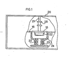
- FIG. 1 shows a housing 20 of a disk storage drive for circular, flexible magnetic foils 16 in firmer rectangular envelope envelopes 17.
- the magnetic circuit foil 16 is inserted with the envelope envelope 17 through an insertion opening (not shown).
- a rotatably mounted tensioning cone 15 which is used for tensioning and rotating the circular film 16.
- the counterpart is a hollow cone 22 which can be rotated by drive devices (not shown) and whose outer housing 24 is fastened to the bottom of the disk storage housing 20.
- Rotary bearings 23 are provided between the outer housing 24 and the hollow cone 22.
- the clamping cone can be rotated about a guide bushing 28, which in turn can be displaced on an axis 21 fixed to the housing.
- FIG. 1 the operating position of the clamping cone 15, in engagement with the hollow cone 22, is shown.
- the guide bushing 28 and the clamping cone 15 are moved out of engagement with the hollow cone 22, so that the sleeve 17 and the film 16 can be pushed in between.
- the clamping and hollow cones 15 and 22 are brought into engagement with one another, as a result of which the film 16 is clamped and driven between the clamping cone 15 and the driving hollow cone 22.
- Figure 2 shows a conical coil spring 25 between the clamping and hollow cone 15 and 22, which is attached to the part 22.
- a cylindrical coil spring or, preferably, because of the smaller space requirement, a leaf spring of any shape can be used.
- Figure 2b shows a spring element 26 made of elastic plastic material, preferably foam, such as e.g.
- the thickness of the spring element 26, which is disk-shaped here, is selected in accordance with the spring constants required and the desired frictional force, since the desired position of the cones 15 and 22 relative to one another and thus the maximum spring travel is predetermined. It is essential, however, that the contact between the clamping cone 15 and the hollow cone 22 takes place via the interposition of the spring element 25 or 26 on the way of the clamping cone 15 up to its desired position, whereby the clamping cone 15 is either spread and thus the film 16 is held in place beforehand and or the cone 15 is also rotated before the film 16 is clamped in the desired position. The hollow cone 22 must therefore be driven prematurely.
- FIGS. 2c and 2d show a decentric arrangement a plastic spring element 27, whereby the centering effect is further enhanced.
- the shape of the spring element 27 - here semi-circular shape - is arbitrary.
- the foam cushion 27 is glued to the bottom of the hollow cone 22.
- a metal spring can also be attached decentrally instead of the foam cushion 27.
- a drive was compared once with and without a spring element in the test.
- a spring element 27 made of polyurethane foam with a thickness of approximately 3 mm and a spring constant of approximately 40 gr / mm, corresponding to approximately 0.4 N / mm, was used.
- the comparative tests were carried out on three different inner hole diameters from Flexydisks®.
- the lower tolerance limit is identified by code number 1, the nominal diameter by 2 and the upper tolerance limit by 3.
- the eccentric deviations of the film center from the target center were determined using 30 clamping tests each.
- the letters A denote the tests without spring elements and B the tests using the spring elements provided according to the invention.
- the eccentricity is reduced for A 1 max - B 1 max by 50 / um (16%), in A 2 max - B 2 max by 20 / um (6.7%) and in A 3 max -B 3 max of 40 / um (13.4%), which corresponds to a track center misalignment according to the given brackets at a standard track width of 300 / um.
- the spring constant of the spring element should expediently be selected in the range from 0.2 N / mm to approximately 1 N / mm. In individual cases, however, deviations from this area, which may be based on device characteristics and various film materials, are possible.
Landscapes
- Holding Or Fastening Of Disk On Rotational Shaft (AREA)
Priority Applications (1)
| Application Number | Priority Date | Filing Date | Title |
|---|---|---|---|
| AT81103428T ATE8721T1 (de) | 1980-05-30 | 1981-05-06 | Laufwerk fuer scheibenfoermige aufzeichnungstraeger. |
Applications Claiming Priority (2)
| Application Number | Priority Date | Filing Date | Title |
|---|---|---|---|
| DE19803020525 DE3020525A1 (de) | 1980-05-30 | 1980-05-30 | Laufwerk fuer kreisfoermige aufzeichnungstraeger |
| DE3020525 | 1980-05-30 |
Publications (2)
| Publication Number | Publication Date |
|---|---|
| EP0041137A1 true EP0041137A1 (fr) | 1981-12-09 |
| EP0041137B1 EP0041137B1 (fr) | 1984-07-25 |
Family
ID=6103562
Family Applications (1)
| Application Number | Title | Priority Date | Filing Date |
|---|---|---|---|
| EP81103428A Expired EP0041137B1 (fr) | 1980-05-30 | 1981-05-06 | Mécanisme d'entraînement pour supports d'enregistrement en forme de disque |
Country Status (5)
| Country | Link |
|---|---|
| US (1) | US4430678A (fr) |
| EP (1) | EP0041137B1 (fr) |
| JP (1) | JPS5720976A (fr) |
| AT (1) | ATE8721T1 (fr) |
| DE (2) | DE3020525A1 (fr) |
Families Citing this family (5)
| Publication number | Priority date | Publication date | Assignee | Title |
|---|---|---|---|---|
| JPS59178659A (ja) * | 1983-03-29 | 1984-10-09 | Fuji Photo Film Co Ltd | フレキシブル磁気デイスク |
| US4827364A (en) * | 1984-04-30 | 1989-05-02 | Xerox Corporation | Self-compensating media centering and clamping mechanism for floppy disk drives |
| US4649445A (en) * | 1984-04-30 | 1987-03-10 | Xerox Corporation | Floating collet suspension for floppy disk drives |
| JPH02114157U (fr) * | 1989-02-23 | 1990-09-12 | ||
| US5056082A (en) * | 1989-06-12 | 1991-10-08 | Ekhoff Donald L | Apparatus for clamping removable disks |
Citations (5)
| Publication number | Priority date | Publication date | Assignee | Title |
|---|---|---|---|---|
| DE2338834A1 (de) * | 1972-07-31 | 1974-02-14 | Matsushita Electric Ind Co Ltd | Vorrichtung zum ein- und rueckfuehren von aufzeichnungsplatten in bzw. aus aufzeichnungs- bzw. wiedergabevorrichtungen |
| US3898814A (en) * | 1974-05-13 | 1975-08-12 | Shugart Associates | Mechanism for clamping and driving a flexible disc |
| DE2524316A1 (de) * | 1974-06-21 | 1976-01-08 | Sycor Inc | Selbstzentrierende nabenanordnung zur lagerung scheibenartiger magnetdatentraeger o.dgl. |
| DE2330818B2 (de) * | 1972-06-21 | 1976-04-22 | International Business Machines Corp., Armonk, N.Y. (V.St.A.) | Vorrichtung zum einspannen und zentrieren von flexiblen folienscheiben |
| DE2709261A1 (de) * | 1976-06-10 | 1977-12-22 | Zentronik Veb K | Aufspannvorrichtung fuer eine flexible magnetplatte |
Family Cites Families (2)
| Publication number | Priority date | Publication date | Assignee | Title |
|---|---|---|---|---|
| JPS527610B1 (fr) * | 1974-06-24 | 1977-03-03 | ||
| US4171531A (en) | 1977-11-09 | 1979-10-16 | Magnetic Peripherals Inc. | Device for centering and driving flexible discs |
-
1980
- 1980-05-30 DE DE19803020525 patent/DE3020525A1/de not_active Withdrawn
-
1981
- 1981-05-01 US US06/259,654 patent/US4430678A/en not_active Expired - Fee Related
- 1981-05-06 AT AT81103428T patent/ATE8721T1/de not_active IP Right Cessation
- 1981-05-06 EP EP81103428A patent/EP0041137B1/fr not_active Expired
- 1981-05-06 DE DE8181103428T patent/DE3165026D1/de not_active Expired
- 1981-05-27 JP JP7943181A patent/JPS5720976A/ja active Pending
Patent Citations (5)
| Publication number | Priority date | Publication date | Assignee | Title |
|---|---|---|---|---|
| DE2330818B2 (de) * | 1972-06-21 | 1976-04-22 | International Business Machines Corp., Armonk, N.Y. (V.St.A.) | Vorrichtung zum einspannen und zentrieren von flexiblen folienscheiben |
| DE2338834A1 (de) * | 1972-07-31 | 1974-02-14 | Matsushita Electric Ind Co Ltd | Vorrichtung zum ein- und rueckfuehren von aufzeichnungsplatten in bzw. aus aufzeichnungs- bzw. wiedergabevorrichtungen |
| US3898814A (en) * | 1974-05-13 | 1975-08-12 | Shugart Associates | Mechanism for clamping and driving a flexible disc |
| DE2524316A1 (de) * | 1974-06-21 | 1976-01-08 | Sycor Inc | Selbstzentrierende nabenanordnung zur lagerung scheibenartiger magnetdatentraeger o.dgl. |
| DE2709261A1 (de) * | 1976-06-10 | 1977-12-22 | Zentronik Veb K | Aufspannvorrichtung fuer eine flexible magnetplatte |
Also Published As
| Publication number | Publication date |
|---|---|
| EP0041137B1 (fr) | 1984-07-25 |
| DE3020525A1 (de) | 1981-12-10 |
| ATE8721T1 (de) | 1984-08-15 |
| US4430678A (en) | 1984-02-07 |
| DE3165026D1 (en) | 1984-08-30 |
| JPS5720976A (en) | 1982-02-03 |
Similar Documents
| Publication | Publication Date | Title |
|---|---|---|
| DE69332938T2 (de) | Verfahren zur Herstellung eines Plattentellers für Plattenaufzeichnungs-/Wiedergabegerät | |
| DE2107184C3 (de) | Magnetplattenspeicher | |
| DE3131889C2 (fr) | ||
| DE69520643T2 (de) | Plattenantriebsvorrichtung mit Plattenhalterungsteller | |
| DE3443070C3 (de) | Abspielgerät für eine mit Informationen versehene Platte | |
| DE69333077T2 (de) | Gleiter-Magnetkopf für magneto-optische Aufzeichnung | |
| DE69011759T2 (de) | Magneto-optisches Aufnahme- und/oder Wiedergabegerät. | |
| CH652522A5 (de) | Kassette fuer eine flexible magnetscheibe und aufzeichnungs- und/oder wiedergabegeraet. | |
| CH656969A5 (de) | Antriebsvorrichtung fuer eine flexible magnetscheibe. | |
| DE69023706T2 (de) | Plattenladevorrichtung. | |
| DE3878957T2 (de) | Plattengerät. | |
| DE2709944B2 (de) | Drehbarer Folienspeicher | |
| DE2450843A1 (de) | Daten-aufzeichnungs- und wiedergabegeraet fuer scheibenartige magnetdatentraeger | |
| DE2529211A1 (de) | Magnetische aufzeichnungsvorrichtung | |
| DE68914518T2 (de) | Plattenantriebsgerät. | |
| EP0041137A1 (fr) | Mécanisme d'entraînement pour supports d'enregistrement en forme de disque | |
| DE69827854T2 (de) | Trägerstruktur eines schwimmend gelagertem Chassis für ein Plattengerät | |
| DE2551455C3 (fr) | ||
| DE3525406A1 (de) | Disketten-kassette | |
| DE3038459C2 (fr) | ||
| DE2326869A1 (de) | Magnetisches aufzeichnungs- und wiedergabegeraet fuer spiralfoermige aufzeichnungsspuren | |
| DE8014659U1 (de) | Laufwerk fuer kreisfoermige aufzeichnungstraeger | |
| DE3433344A1 (de) | Aufzeichnungs- und/oder wiedergabegeraet | |
| DE2034236A1 (de) | Magnetkopfanordnung | |
| DE2709261A1 (de) | Aufspannvorrichtung fuer eine flexible magnetplatte |
Legal Events
| Date | Code | Title | Description |
|---|---|---|---|
| PUAI | Public reference made under article 153(3) epc to a published international application that has entered the european phase |
Free format text: ORIGINAL CODE: 0009012 |
|
| AK | Designated contracting states |
Designated state(s): AT BE CH DE FR GB IT NL SE |
|
| 17P | Request for examination filed |
Effective date: 19811022 |
|
| ITF | It: translation for a ep patent filed | ||
| GRAA | (expected) grant |
Free format text: ORIGINAL CODE: 0009210 |
|
| AK | Designated contracting states |
Designated state(s): AT BE CH DE FR GB IT LI NL SE |
|
| PG25 | Lapsed in a contracting state [announced via postgrant information from national office to epo] |
Ref country code: SE Effective date: 19840725 Ref country code: BE Effective date: 19840725 |
|
| REF | Corresponds to: |
Ref document number: 8721 Country of ref document: AT Date of ref document: 19840815 Kind code of ref document: T |
|
| REF | Corresponds to: |
Ref document number: 3165026 Country of ref document: DE Date of ref document: 19840830 |
|
| ET | Fr: translation filed | ||
| PG25 | Lapsed in a contracting state [announced via postgrant information from national office to epo] |
Ref country code: AT Effective date: 19850506 |
|
| PG25 | Lapsed in a contracting state [announced via postgrant information from national office to epo] |
Ref country code: LI Effective date: 19850531 Ref country code: CH Effective date: 19850531 |
|
| PLBE | No opposition filed within time limit |
Free format text: ORIGINAL CODE: 0009261 |
|
| STAA | Information on the status of an ep patent application or granted ep patent |
Free format text: STATUS: NO OPPOSITION FILED WITHIN TIME LIMIT |
|
| 26N | No opposition filed | ||
| REG | Reference to a national code |
Ref country code: CH Ref legal event code: PL |
|
| PGFP | Annual fee paid to national office [announced via postgrant information from national office to epo] |
Ref country code: NL Payment date: 19870531 Year of fee payment: 7 |
|
| PG25 | Lapsed in a contracting state [announced via postgrant information from national office to epo] |
Ref country code: GB Effective date: 19890506 |
|
| PG25 | Lapsed in a contracting state [announced via postgrant information from national office to epo] |
Ref country code: DE Effective date: 19890606 |
|
| PG25 | Lapsed in a contracting state [announced via postgrant information from national office to epo] |
Ref country code: NL Effective date: 19891201 |
|
| GBPC | Gb: european patent ceased through non-payment of renewal fee | ||
| NLV4 | Nl: lapsed or anulled due to non-payment of the annual fee | ||
| PG25 | Lapsed in a contracting state [announced via postgrant information from national office to epo] |
Ref country code: FR Free format text: LAPSE BECAUSE OF NON-PAYMENT OF DUE FEES Effective date: 19900131 |
|
| REG | Reference to a national code |
Ref country code: FR Ref legal event code: ST |