EP0042085A1 - Dispositif pour transporter le papier dans des machines à écrire et autres machines de bureau - Google Patents
Dispositif pour transporter le papier dans des machines à écrire et autres machines de bureau Download PDFInfo
- Publication number
- EP0042085A1 EP0042085A1 EP81104031A EP81104031A EP0042085A1 EP 0042085 A1 EP0042085 A1 EP 0042085A1 EP 81104031 A EP81104031 A EP 81104031A EP 81104031 A EP81104031 A EP 81104031A EP 0042085 A1 EP0042085 A1 EP 0042085A1
- Authority
- EP
- European Patent Office
- Prior art keywords
- switch
- switching
- control
- control element
- switching movement
- Prior art date
- Legal status (The legal status is an assumption and is not a legal conclusion. Google has not performed a legal analysis and makes no representation as to the accuracy of the status listed.)
- Granted
Links
Images


Classifications
-
- B—PERFORMING OPERATIONS; TRANSPORTING
- B41—PRINTING; LINING MACHINES; TYPEWRITERS; STAMPS
- B41J—TYPEWRITERS; SELECTIVE PRINTING MECHANISMS, i.e. MECHANISMS PRINTING OTHERWISE THAN FROM A FORME; CORRECTION OF TYPOGRAPHICAL ERRORS
- B41J11/00—Devices or arrangements of selective printing mechanisms, e.g. ink-jet printers or thermal printers, for supporting or handling copy material in sheet or web form
- B41J11/36—Blanking or long feeds; Feeding to a particular line, e.g. by rotation of platen or feed roller
- B41J11/38—Manually-operated feeding devices
-
- B—PERFORMING OPERATIONS; TRANSPORTING
- B41—PRINTING; LINING MACHINES; TYPEWRITERS; STAMPS
- B41J—TYPEWRITERS; SELECTIVE PRINTING MECHANISMS, i.e. MECHANISMS PRINTING OTHERWISE THAN FROM A FORME; CORRECTION OF TYPOGRAPHICAL ERRORS
- B41J19/00—Character- or line-spacing mechanisms
- B41J19/76—Line-spacing mechanisms
- B41J19/78—Positive-feed mechanisms
- B41J19/96—Variable-spacing arrangements
Definitions
- the invention relates to a device for transporting recording paper in typewriters and the like. Office machines according to the preamble of claim 1.
- an automatic paper feed is desirable which, once triggered, always brings each recording paper inserted into the writing mechanism into the same line position at the start of writing.
- an electric drive motor can be used, which in its forward and reverse runs over a predetermined sequence of steps or over the period of time the step movement to be carried out can be excited and which is switched off at the end of the step movement by means of an electronic counter preprogrammed to the respectively desired step length or angular movement corresponding to a specific number of lines or position.
- a paper feed device in which a motorized paper feed with fast and slow forward and reverse is possible is known from DE-OS 20 56 564.
- the machine described here has 4 controls, of which a first button for triggering a step movement of the feed device in the forward direction, a second button for triggering a step movement in the backward direction, a first slide switch for a slow continuous feed movement and a second slide switch for fast continuous feed movement are provided is.
- the slide switches can be displaced from a zero position in two opposite directions, displacement in one direction triggering a forward feed movement and displacement in the opposite direction triggering a reverse feed movement.
- Such a device offers an operator the possibility of positioning a record carrier precisely line by line in the forward or backward direction, but also accelerating larger feed movements and rapidly inserting or ejecting the record carrier.
- the known device is difficult to operate because of the large number of operating elements, which is why the operator requires a longer familiarization period and the given functions are not used optimally.
- a paper feed device in office machines has also become known (DE-AS 27 31 182) with a clockwise direction and counterclockwise pivotable from a rest position, which can be detected outside the machine housing.
- switching elements are acted on one after the other via control cams provided on the operating lever.
- B. stepper motor a car lift or a carriage movement and then one over a second z.
- B. trigger stepper motor caused retraction of the recording paper.
- the line switching step motor is actuated for a reverse paper transport movement via a further switching element.
- the implementation of the respective switching signal or the current switching state of the switching elements takes place in a process control device.
- the control lever returns after releasing it under spring action. With the operating lever, only as many switching states can be achieved as there are ultimately switching elements. The combination of different switching states for further evaluation by means of a status query is not provided.
- DE-AS 12 90 743 discloses a device for selecting the gaits in computing machines with an adjusting lever with which a large number of gaits to be selected can be determined. The gaits are triggered after the calculations.
- the adjusting lever can be pressed as well as swung forward or backward in the pressed position.
- Connected to the adjusting lever via an adjusting slide are a number of switching cams which, when the adjusting lever is adjusted, come into a predeterminable position, in which they in turn interact with switching approaches which act on gait buttons.
- the second switching movement which runs essentially in the pressure direction, serves to lock and unlock the adjusting lever.
- the switching movements of the setting lever do not work towards a common interrogation unit.
- an ink writing mechanism shown in sections is positioned at 1.
- the printing station can be seen with a transport roller 2 for the recording paper 3.
- the recording paper can be both a single sheet and a recording paper which is fixed in its width and has been drawn off from a supply roll.
- an ink writing head 4 is used for the representation of characters and symbols of an alphanumeric type, which is mounted on a writing carriage 5 and can be moved step by step and / or continuously in the two line directions by a motor (which has not been shown).
- the ink writing head 4 can thus also be guided out of the writing area, which is essentially determined by the length of the transport roller 2 and corresponding to the width of the recording paper 3, into one or more edge areas to the side of the transport roller 2.
- the carriage 5 is slidably mounted on guide rods 6.
- Other elements for driving the carriage or the ink writing head have not been shown since they are easy to imagine.
- a motor-driven shaft 7 is shown, which is connected to a stepper motor or a direct current motor which can be moved quickly and slowly in forward and reverse runs.
- the motor and the transmission link to the motor-driven shaft have also not been shown.
- the shaft 7 is connected via a toothed belt 8 to the transport roller 2, for example, so that it follows the movement of the motor.
- the control lever 9 has a control element 10 with a first control curve 11 shown on the left and a second control curve 12 shown on the right, and a contact surface 13 in the lower middle part, as well as a control curve 14 essentially perpendicular to the first control curve 11 and one Control curve 15 running perpendicular to the second control curve 12. Furthermore, a first switch 16, a second switch 17 and a third switch 18 have been shown with the connections 19 as switch inputs and the connections 20, 21 and 22 as switch outputs.
- the switching elements 16, 17, 18 can be microswitches, but other switches and switching position interrogation elements are possible, such as optical, capacitive or inductive interrogation elements.
- the switches 16, 17 and 18 each have a switch lever 23, 24 and 25, which cooperate with the control cams 11, 12, 13, 14 and 15. The interaction of these will be described later in FIGS. 2 to 4.
- the control lever 9 is via a rotating leg spring 26 and the resilient legs 26 1 1 and 26 2 held in a predetermined zero position.
- the torsion spring 26 is placed around a pin 29, which at the same time represents a bearing point for the operating lever 9.
- the legs 26 1 and 26 2 of the torsion spring 26 rest on the support points 27 and 28 of the operating lever and, in their extension, on a further pin 30, which serves to determine the possible movements of the operating lever 9.
- the operating lever is guided in its upper part in a slot-like guide groove 31, so that it is pivotable on the one hand about the pin 29 and on the other hand is longitudinally displaceable in the guide groove 31.
- a circular arc-shaped guide groove 32 In its essentially opposite area there is a circular arc-shaped guide groove 32, which is also designed in the manner of an elongated hole.
- This guide groove is first in a first partial area 33 for tilting or pivoting the operating lever clockwise and with a further partial area 34 for tilting or Swiveling the control lever counterclockwise from a zero or rest position.
- Another guide groove 35 for the longitudinal displaceability of the operating lever and thus for triggering pressure on the handle 9 1 merges into the circular-shaped guide groove 32 in the central part thereof.
- a tension spring 36 is stretched on the one hand between a pin 37 fixed to the frame and a suspension bracket 39 on the operating lever 9 for returning the operating lever to a non-pressed position.
- the first switching movement is 40
- the second switching movement denoted by 41 the third shifting movement is denoted by 42
- the fourth shifting movement is denoted by 43.
- the operating lever 9 can be pressed out of the rest position into a first vertical switching movement 46 and into a second switching movement 47 to be carried out in the same direction.
- FIG. 2 shows the part of the operating lever 9 which on the one hand has the guide groove 31 and the guide groove 32 and the guide groove 35 and on the other hand that with the switches 16, 17 and 18 (FIG. 1) or their switch levers 23, 24 and 25 cam 11, 12, 13, 14 and 15 which can be brought into operative connection.
- the operating lever 9 In the upper part of the operating lever 9, the guide groove 31 can be seen and the pin 29 penetrating the operating lever 9 at this point.
- the operating lever 9 In its lower part, the operating lever 9 has the circular-shaped guide groove 32 with the partial areas 33 and 34 and the guide groove 35.
- the guide groove 32 , 35 is penetrated here by the pin 30 and it can be seen that when the operating lever is actuated, it is guided in one of a first, a second or a third switching movement direction. If the operating lever is moved in a clockwise direction and thus in the switching movement direction 44 from the 0 position in a first switching movement 40, the control cam part 10 shifts to a position which is shown in a broken line with a point in the course of the line.
- FIG. 3 shows the operating lever 9 corresponding to the third and fourth switching movements in the switching movement direction 45
- Control lever 9 pivoted counterclockwise in the third switching movement 42 the Sc a ter ee 25 comes into switching function via the control cam 12.
- the position of the control curve 10 is shown in a broken line with a point in the line course.
- the switch lever 25 remains in the switched position and the control lever 11 brings the switch lever 24 into a position that switches the switch 17 (FIG. 1).
- the control curve 10 in the position of the fourth switching movement has been shown with an interrupted line and two points arranged along the line.
- FIG. 4 shows the switch positions which, by depressing the operating lever from the rest position 0, into the first vertical switching movement 46 and into the second switching movement 47.
- the rest position of the curve part 10 is shown in a full line, the position of the curve part 10 in the first vertical switching movement 46 by an interrupted line with one point and to distinguish it the position of the second switching movement 47 with an interrupted line with two points.
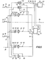
- the circuit arrangement according to FIG. 5 is used to query and evaluate the switch positions of switches 16, 17 and 18 are the line inputs of the switches, with 20, '21 and 22 the respective outputs.
- the output 20 of the switch 16 is connected to an active switching element 52, which can be a transistor, for example, to an input 54 of an AND gate 48 and to an input 67 of an AND gate 51.
- the output 21 of the switch 17 is connected to the input 55 of the AND gate 48, to the input 58 of an AND gate 49 and to the input 62 of an AND gate 50.
- a signal can be derived via line 84, which is led to a control input of the motor control for the motor for the horizontal carriage movement.
- the output 22 of the switch 18 is connected to an active switching element 53, which can also be a transistor, for example, to the input 59 of the AND gate 49 and to the input 66 of the AND gate 51.
- 38 denotes an input which always derives a signal from an interrogation station when the carriage 5 has been moved to the left edge position with the ink writing head 4 (FIG. 1).
- the line 38 is connected to the input 56 of the AND gate 48, to the input 60 of the AND gate 49 and to the input 64 of the AND gate 50.
- the output of the AND gate 48 is connected to the switching input 69 of the active switching element 52 and to an input 71 of the counter element 75.
- the counter also has the meaning of the timing of the motor control circuit 82.
- the output 61 of the AND gate 49 is connected to the control input 70 of the active switch element 53 and to the input 72 of the counter element 75.
- the output 65 of the AND gate 50 is connected to the input 73 of the counter 75.
- the output 68 of the AND gate 51 is connected to the input 74 of the counter element 75 and to the input 63 of the AND gate 50.
- the output of the active switch element 52 is connected to the input 81 of a circuit 82 for motor control.
- the exit of the active Switch element 53 is connected to input 80 of circuit 82 for motor control.
- the outputs 75 and 77 of the counter 75 have been connected to the inputs 79 and 78 of the circuit for the motor control 82.
- the circuit 82 for motor control serves to control the motor via line 83 in its fast and slow forward and reverse runs.
- the functions of querying the switching states and converting them into control commands can also be carried out by a microprocessor in a corresponding design.
- the mode of operation of the circuit arrangement according to FIG. 5 is now as follows. If the switch 16 is actuated, the first switching movement 40, a signal is applied to the circuit 82 via the input 81 via the active switch element 52. This signal causes a slow motor feed current in the circuit 82 via the line 83. It is understood that the active element 52 must be closed in this case. The active element 52 is only open when a signal is present via the signal input 69 when all signals are present at the inputs 54, 55, 56 of the AND gate 48.
- the switch 17 is also actuated to the switch 16, so that in addition to the pending signals at 54 and 55 of the AND gate 48, a signal is also on the line 84, so that the motor for the horizontal positioning, that is to say for the carriage and thus the ink writing head 4 movement into its edge position is triggered. If the ink writing head is in this position, there is also a signal at input 56 via input 38, so that AND gate 48 switches, via output 57 the active switch element 52 being interrupted via input 69 and at which Counter 75 receives a signal via its input 71 until the operating lever 9 is brought out of this position.
- the switch 18 remains closed and the switch 17 is closed, so that there is a signal on the line 84 which causes the ink writing head 4 to return to the edge position.
- an interrogation device When the edge position is reached, an interrogation device generates a signal via line 38 which, with the signals from switches 17 at input 58, from switch 18 at input 59 and even at input 60 of AND gate 49, produces an output signal at output 61.
- the Ajsgangsignal is present at the input 70 on the active switch element 53 and opens it and it causes a signal via the input 72 on the counter element 75, which is present via its output 77 at the input 78 of the circuit 82 of the motor control as long as the switches 17 and 18 are switched on are.
- the switch 17 is also closed, so that a signal is present on the line 84, which triggers the aforementioned process of returning the ink writing head to an edge position, so that it also acts on the signal line 38 a signal is present.
- the AND gate 51 is still switched and there is a signal via its output 68 and the input 63 at the AND gate 50.
- a signal is present at the input 62 of the AND gate 50 from the switch 17 and at the input 64 of the AND gate 50 from the input 38, so that when the ink writing head is returned to its edge position via the signal on line 84, it is now via the output 65 of the AND gate, a signal is present at the input 73 of the counter, which in turn becomes active in the sense that a predetermined number of signals is at the output 76 and thus at the input 79 of the circuit 82, so that the motor for the recording paper in the sense of a predetermined (automatic) feed movement.
- the inputs 81 and 80 are used in the order of the slow forward and slow return of the motor controlled via the output line 83, the inputs 79 and 78 of the circuit 82 for the fast runs and in the order of the fast return and the fast forward of the motor which can be controlled via the output line 83. If switches 16 and 18 are actuated simultaneously, the active elements 52 and 53 are also acted upon and the inputs 81 and 80 of the control circuit 82 carry a signal.
- the circuit for the motor control 82 has a priority circuit, so that the signals on the input lines 81 and 80 remain ineffective since only individual steps. should come into effect via the output 68 of the AND gate 51 on the input line 74 of the counter 75 and thus on the input line 78 of the circuit 82.
- An operating element 101 designed as a handwheel is operatively connected to the tap 102 of a potentiometer 103 in such a way that the tap 102 is correspondingly displaced on one of the two resistance tracks 104, 105 by rotating the handwheel 101.
- a second operative connection exists between the handwheel 101 and a switch 106, which can be moved from the open position shown into a closed position by axially displacing the handwheel 101.
- the active connections which can be implemented by the person skilled in the art are indicated by dash-dotted lines 107, 108.
- the potentiometer 103 and the switch 106 are connected to the machine control 109, which, among other things, evaluates voltage values picked up by the potentiometer 103 in an evaluation circuit for controlling a feed drive motor in the feed device 110 for a vertical displacement of a recording medium 111.
- the evaluation circuit can, for. B. be formed by an oscillator circuit, the output frequency is variable according to the size of the voltage taken from the tap 102 and is used for the gradual control of the feed drive motor. Tapping a voltage value from one resistance track 104 causes the feed to move in the forward direction, tapping a voltage value from the other resistance track 105 in the reverse direction. Both a stepper motor and a step-by-step direct or alternating current motor can be used as the feed drive motor.
- the switch 106 is used to change the feed step size. In the open position of the switch 106, the recording medium 111 is increased by z. B. 1/12 inch moved while in the closed position of the switch, the step size z. B. is 1/60 inch.
- the recording medium 111 is thus transported step by step in the forward direction, with the individual steps being lined up with a relatively large time interval, but the time interval becoming smaller and smaller as the rotation increases, and at maximum rotation, the steps are finally so close together that they are equivalent to a rapid continuous feed.
- the feed function described is carried out in the reverse direction. If the handwheel 101 is moved in the direction of arrow 131 before or during the rotation, the described forward or backward displacement function is carried out with finer step division.
- FIG. 7 Another embodiment is shown in FIG. 7, which in turn has a rotatable and an axially displaceable handwheel 112, a machine control 113 and a feed device 114 for vertically displacing a recording medium 115, but in which instead of the potentiometer of FIG. 6, a scanner 116 detectable code track carrier 117 is provided.
- Four contact tracks 118 to 121 are provided, which are in contact with four wipers of the scanner 116.
- An input signal is supplied via the inner contact track 121, and a code formed from three L / O signals in accordance with the contact assignment of the tracks in the respective scanning position is taken from the three outer contact tracks 118 to 120 and sent to the machine controller 113.
- both the handwheel 112 and the scanner 116 assume the zero position and the code LLL is given to the machine control system (e.g. a microprocessor) which causes the feed drive to stop.
- the machine control system e.g. a microprocessor
- the code LOL is emitted when entering the area 123, which causes a slow incremental feed in the forward direction.
- the code LOO has been delivered
- a faster feed is initiated
- the last area 125 after the code 000 has been scanned, a particularly rapid feed intended especially for the insertion and ejection of the recording medium.
- Rotation of the handwheel 112 in the direction 130 leads to the scanning of the code LLO in the first area 126, which causes a slow gradual backward shift, and in the next area 127 to the scanning of the code OLO, which results in a fast backward shift.
- the rotation path of the handwheel 112 is thus divided into areas assigned to different speeds, which is why the speed change of the feed movement is gradual - in contrast to the exemplary embodiment in FIG. 6, where the speed change takes place continuously. In contrast, an area is provided for the zero position in both exemplary embodiments.
- Shifting the handwheel 112 in the direction of the arrow 131 causes the step size to be switched via a switch 128, as has already been explained in more detail in relation to FIG.
Landscapes
- Character Spaces And Line Spaces In Printers (AREA)
Applications Claiming Priority (4)
| Application Number | Priority Date | Filing Date | Title |
|---|---|---|---|
| DE19803022038 DE3022038A1 (de) | 1980-06-12 | 1980-06-12 | Vorrichtung zum transport von aufzeichnungspapier in schreib- u.dgl. |
| DE3022038 | 1980-06-12 | ||
| DE19803039789 DE3039789A1 (de) | 1980-10-22 | 1980-10-22 | Vorschubeinrichtung in elektrisch angetriebenen schreib- o.ae. maschinen |
| DE3039789 | 1980-10-22 |
Publications (2)
| Publication Number | Publication Date |
|---|---|
| EP0042085A1 true EP0042085A1 (fr) | 1981-12-23 |
| EP0042085B1 EP0042085B1 (fr) | 1985-01-16 |
Family
ID=25785970
Family Applications (1)
| Application Number | Title | Priority Date | Filing Date |
|---|---|---|---|
| EP81104031A Expired EP0042085B1 (fr) | 1980-06-12 | 1981-05-26 | Dispositif pour transporter le papier dans des machines à écrire et autres machines de bureau |
Country Status (2)
| Country | Link |
|---|---|
| EP (1) | EP0042085B1 (fr) |
| DE (1) | DE3168272D1 (fr) |
Citations (2)
| Publication number | Priority date | Publication date | Assignee | Title |
|---|---|---|---|---|
| DE1151523B (de) * | 1959-06-08 | 1963-07-18 | Olympia Werke Ag | Vorrichtung zum Steuern von Zeilenschalteinrichtungen an Schreib- und aehnlichen Maschinen |
| CH512331A (de) * | 1969-11-19 | 1971-09-15 | Ibm | Zeilenschaltvorrichtung für Druckwerke |
-
1981
- 1981-05-26 DE DE8181104031T patent/DE3168272D1/de not_active Expired
- 1981-05-26 EP EP81104031A patent/EP0042085B1/fr not_active Expired
Patent Citations (2)
| Publication number | Priority date | Publication date | Assignee | Title |
|---|---|---|---|---|
| DE1151523B (de) * | 1959-06-08 | 1963-07-18 | Olympia Werke Ag | Vorrichtung zum Steuern von Zeilenschalteinrichtungen an Schreib- und aehnlichen Maschinen |
| CH512331A (de) * | 1969-11-19 | 1971-09-15 | Ibm | Zeilenschaltvorrichtung für Druckwerke |
Also Published As
| Publication number | Publication date |
|---|---|
| DE3168272D1 (en) | 1985-02-28 |
| EP0042085B1 (fr) | 1985-01-16 |
Similar Documents
| Publication | Publication Date | Title |
|---|---|---|
| DE2424888A1 (de) | Geraet zum lesen und beschreiben datenspeichernder registrierkarten | |
| EP0038290B1 (fr) | Appareil de commande pour une machine à imprimer, en particulier une machine à imprimer avec une matrice | |
| DE2830703A1 (de) | Einrichtung zur papiereinfuehrung, zum papiertransport und zur papierausgabe in einem schnelldrucker | |
| DE2654294C3 (de) | Reihendrucker | |
| DE2717758C3 (de) | Vorrichtung zur Papierführung in Druckgeräten, insbesondere bei Daten- und Fernschreibmaschinen | |
| DE2059154A1 (de) | Einrichtung zum seriellen Drucken | |
| DE2927869C2 (fr) | ||
| DE2715428C2 (de) | Vorrichtung zum Bedrucken von Formularen, insbesondere von Tickets | |
| EP0645333B1 (fr) | Guide réglable pour matériau en bande | |
| DE2633851C2 (de) | Einlaufvorrichtung an einem Belichtungsteil einer Lichtpausmaschine | |
| DE4205777C2 (de) | Drucker für die Verarbeitung von Aufzeichnungsträgern unterschiedlicher Dicke in Form von Einzelblättern und Endlosbahnen | |
| DE69014714T2 (de) | Automatische Zuführvorrichtung für einen Drucker. | |
| DE1262645B (de) | Rasterdrucker | |
| EP0042085B1 (fr) | Dispositif pour transporter le papier dans des machines à écrire et autres machines de bureau | |
| DE2710525C2 (de) | Verfahren zum Steuern des Druckvorganges bei Datenschreibern | |
| DE3419257C2 (de) | Vorrichtung zum Steuern einer Papiertransportvorrichtung in Druckeinrichtungen | |
| DE3419254C1 (de) | Kopiergeraet mit Kopielocheinrichtung | |
| DE2738968A1 (de) | Vorrichtung zum schneiden von aufzeichnungstraegern | |
| DE2162230A1 (de) | Seriendruckwerk fuer mosaikdruck | |
| DE1809654C3 (de) | Vorrichtung zum selbsttätigen Anpassen des Kulierweges an die jeweilige Arbeitsbreite bei flachen Kulierwirkmaschinen | |
| DE4035037A1 (de) | Einrichtung zur axialen einstellung von saugringen in bogenbremsen von druckmaschinen | |
| DE3783451T2 (de) | Korrekturvorrichtung fuer schreibmaschinen. | |
| DE3709127A1 (de) | Automatische papiereinziehvorrichtung fuer drucker | |
| DE3022038A1 (de) | Vorrichtung zum transport von aufzeichnungspapier in schreib- u.dgl. | |
| DE1141296B (de) | Greifersteuerung an Kettenauslegern von Druckmaschinen |
Legal Events
| Date | Code | Title | Description |
|---|---|---|---|
| PUAI | Public reference made under article 153(3) epc to a published international application that has entered the european phase |
Free format text: ORIGINAL CODE: 0009012 |
|
| AK | Designated contracting states |
Designated state(s): CH DE FR GB IT NL SE |
|
| 17P | Request for examination filed |
Effective date: 19811026 |
|
| ITF | It: translation for a ep patent filed | ||
| GRAA | (expected) grant |
Free format text: ORIGINAL CODE: 0009210 |
|
| AK | Designated contracting states |
Designated state(s): CH DE FR GB IT LI NL SE |
|
| REF | Corresponds to: |
Ref document number: 3168272 Country of ref document: DE Date of ref document: 19850228 |
|
| ET | Fr: translation filed | ||
| PLBE | No opposition filed within time limit |
Free format text: ORIGINAL CODE: 0009261 |
|
| STAA | Information on the status of an ep patent application or granted ep patent |
Free format text: STATUS: NO OPPOSITION FILED WITHIN TIME LIMIT |
|
| 26N | No opposition filed | ||
| PGFP | Annual fee paid to national office [announced via postgrant information from national office to epo] |
Ref country code: NL Payment date: 19860531 Year of fee payment: 6 |
|
| PG25 | Lapsed in a contracting state [announced via postgrant information from national office to epo] |
Ref country code: SE Effective date: 19870527 |
|
| PG25 | Lapsed in a contracting state [announced via postgrant information from national office to epo] |
Ref country code: LI Effective date: 19870531 Ref country code: CH Effective date: 19870531 |
|
| PG25 | Lapsed in a contracting state [announced via postgrant information from national office to epo] |
Ref country code: NL Effective date: 19871201 |
|
| NLV4 | Nl: lapsed or anulled due to non-payment of the annual fee | ||
| PG25 | Lapsed in a contracting state [announced via postgrant information from national office to epo] |
Ref country code: FR Free format text: LAPSE BECAUSE OF NON-PAYMENT OF DUE FEES Effective date: 19880129 |
|
| REG | Reference to a national code |
Ref country code: CH Ref legal event code: PL |
|
| PG25 | Lapsed in a contracting state [announced via postgrant information from national office to epo] |
Ref country code: DE Effective date: 19880202 |
|
| GBPC | Gb: european patent ceased through non-payment of renewal fee | ||
| REG | Reference to a national code |
Ref country code: FR Ref legal event code: ST |
|
| PG25 | Lapsed in a contracting state [announced via postgrant information from national office to epo] |
Ref country code: GB Free format text: LAPSE BECAUSE OF NON-PAYMENT OF DUE FEES Effective date: 19881118 |
|
| EUG | Se: european patent has lapsed |
Ref document number: 81104031.0 Effective date: 19880601 |