EP0042690A1 - Stromabnahmevorrichtung für elektrische Fahrzeuge und deren Zuführungssysteme - Google Patents
Stromabnahmevorrichtung für elektrische Fahrzeuge und deren Zuführungssysteme Download PDFInfo
- Publication number
- EP0042690A1 EP0042690A1 EP19810302549 EP81302549A EP0042690A1 EP 0042690 A1 EP0042690 A1 EP 0042690A1 EP 19810302549 EP19810302549 EP 19810302549 EP 81302549 A EP81302549 A EP 81302549A EP 0042690 A1 EP0042690 A1 EP 0042690A1
- Authority
- EP
- European Patent Office
- Prior art keywords
- current
- collection
- conductors
- elements
- vehicle
- Prior art date
- Legal status (The legal status is an assumption and is not a legal conclusion. Google has not performed a legal analysis and makes no representation as to the accuracy of the status listed.)
- Granted
Links
- 239000004020 conductor Substances 0.000 claims abstract description 139
- 238000012546 transfer Methods 0.000 claims abstract description 17
- 230000008878 coupling Effects 0.000 claims description 6
- 238000010168 coupling process Methods 0.000 claims description 6
- 238000005859 coupling reaction Methods 0.000 claims description 6
- 230000008859 change Effects 0.000 abstract description 4
- 238000006073 displacement reaction Methods 0.000 abstract 1
- 230000004048 modification Effects 0.000 description 6
- 238000012986 modification Methods 0.000 description 6
- 238000010276 construction Methods 0.000 description 3
- 238000013459 approach Methods 0.000 description 2
- 241000269350 Anura Species 0.000 description 1
- 230000008901 benefit Effects 0.000 description 1
- 230000015556 catabolic process Effects 0.000 description 1
- 230000001419 dependent effect Effects 0.000 description 1
- 238000011161 development Methods 0.000 description 1
- 238000010586 diagram Methods 0.000 description 1
- 239000012777 electrically insulating material Substances 0.000 description 1
- 239000011810 insulating material Substances 0.000 description 1
- 239000000463 material Substances 0.000 description 1
- 238000000034 method Methods 0.000 description 1
- 230000007935 neutral effect Effects 0.000 description 1
- 229920003023 plastic Polymers 0.000 description 1
- 239000004033 plastic Substances 0.000 description 1
- 230000008569 process Effects 0.000 description 1
- 238000000926 separation method Methods 0.000 description 1
- 230000007704 transition Effects 0.000 description 1
Images


Classifications
-
- B—PERFORMING OPERATIONS; TRANSPORTING
- B60—VEHICLES IN GENERAL
- B60M—POWER SUPPLY LINES, AND DEVICES ALONG RAILS, FOR ELECTRICALLY- PROPELLED VEHICLES
- B60M3/00—Feeding power to supply lines in contact with collector on vehicles; Arrangements for consuming regenerative power
-
- B—PERFORMING OPERATIONS; TRANSPORTING
- B60—VEHICLES IN GENERAL
- B60L—PROPULSION OF ELECTRICALLY-PROPELLED VEHICLES; SUPPLYING ELECTRIC POWER FOR AUXILIARY EQUIPMENT OF ELECTRICALLY-PROPELLED VEHICLES; ELECTRODYNAMIC BRAKE SYSTEMS FOR VEHICLES IN GENERAL; MAGNETIC SUSPENSION OR LEVITATION FOR VEHICLES; MONITORING OPERATING VARIABLES OF ELECTRICALLY-PROPELLED VEHICLES; ELECTRIC SAFETY DEVICES FOR ELECTRICALLY-PROPELLED VEHICLES
- B60L5/00—Current collectors for power supply lines of electrically-propelled vehicles
- B60L5/36—Current collectors for power supply lines of electrically-propelled vehicles with means for collecting current simultaneously from more than one conductor, e.g. from more than one phase
Definitions
- This invention relates to a current collection apparatus for an electric vehicle and an electrical supply system therefor.
- the minimum number of current conductors for the supply of electrical power consists of a current conductor for each specific "energising characteristic" (i.e. each polarity of phase) of the system.
- a direct current (D.C.) system has two conductors; a single phase alternating current system has two conductors and a three phase delta alternating current system has a minimum of three conductors.
- D.C. direct current
- Patent No. 407,546 merely discloses a number of contacts corresponding. to the number of current conductors in a given lane i.e. two contacts for direct current and three contacts for a three phase system.
- Patent of Addition No. 476,546 does disclose in one embodiment with a supply system in which pairs of conductors occurring in the same relative order,(i.e. polarities 1,2,1,2) and in which the contact member has four contacts.
- the distance between adjacent conductors which is the same all along the web, is equal to the distance between the centres of the sliding contacts, and the width of each sliding contact is made less than the distance between two adjacent conductors, so as not to short circuit the line when transverse movement takes place.
- the disclosure is totally silent as to the manner in which the collection apparatus feeds the current to the vehicle and whether direct current or alternating current motors are employed in the vehicle.
- dead spots inevitably occur as the vehicle moves transversely of the conductors since at certain transverse locations of the contacts relative to the conductors there is no electrical connection therebetween and thus, at best, an intermittent electrical coupling.
- the present invention seeks to avoid these disadvantages by providing current collection apparatus for an electric vehicle which is capable of providing the electrical power for vehicle traction from an electrical supply system, routed along the vehicle route, wherein the lateral movement of the vehicle relative to the path of the conduction linesis not dependent on a mechanical shift of the collection elements relative to the vehicle, but is achieved by a change of effective electrical coupling from one set of conductor lines during which current collection is continuous, and entailing the use, at least at certain vehicle route positions, of an auxiliary conductor or auxiliary conductors in addition to said minimum number of conductors.
- current collection apparatus for an electric vehicle energised by an electrical supply system routed along the vehicle route, comprising collection means having a plurality of collection elements, the number of collection elements
- each terminal means in use, receives current of a respective polarity, said collection elements being arranged such that, when presented to a system of current conductors, the arrangement of the elements avoids short-circuiting of the current conductors whilst at all times said arrangement affords a current path between each terminal means and a current conductor.
- a direct current supply for use in a vehicle may be derived from an electrical supply routed along the vehicle route in the form of a direct current supply, a single phase alternating current supply or even a three phase delta, alternating current supply.
- the vehicle supply only requires first terminal means carrying current of a first polarity (positive/live) and a second terminal means carrying current of a second polarity (negative/ neutral).
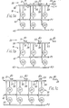
- the current collection apparatus 10 for an electric vehicle is shown disposed in close proximity to an electrical supply system 20 routed along a vehicle route and including current conductors 21 to 23 or 24.
- the apparatus 10 has collection means 30 with a first series of collection elements 31 to 33 (Figs. 1A, 1B) and 31 to 34 (Fig. 1C): in practice elements 31 to 33 actually contact the current conductors 21 to 23 or 21 to 24.
- the number of the collection elements which is the three elements 31 to 33 in Figs. 1A and 1B and the four elements 31 to 34 in Fig. 1C correspond to the number of current conductors carrying different energising characteristics in each of the supply systems of Figs.
- Figs. 1A to 1C respectively (as will be explained) plus a transfer or 'auxiliary' conductor.
- the energising characteristics of the current conductors in Figs. 1A to 1C are indicated by Pl, P2 for positive polarity and negative polarity (or vice versa) in Fig. lA, ⁇ 1 , ⁇ 2 for positive and negative phase in Fig. 1B and ⁇ 1 , ⁇ 2 , ⁇ 3 for three different phases in Fig. 1C.
- the supply system of Figs. 1A and 1B has two different energising characteristics and collection means for use therewith has at least the three collection elements 31 to 33.
- Notionally conductor 23 may be regarded as an auxiliary or transfer conductor in Figs.
- the pitch A and width C of the current conductors 21 to 24 have been shown to be regular.
- the width B and separation D of the collection elements has been shown to be regular.
- the collection elements 31 to 33 or 31 to 34 have been shown in parallel (laterally of the current conductors 21 to 23/24). Such geometry may be varied without departing from the present invention.
- the nature of the collection elements 31 to 33 or 31 to 34 and the current conductors 21 to 24 will depend on the type of vehicle and the location of the current conductors relative to the vehicle route.
- the main application envisaged is in connection with trolley buses for which the collection means will be a collection bar 30 with conductive segments forming the collection elements 31 to 33 or 34 and insulating segments 36 therebetween.
- the current conductors 21 to 24 are overhead cables suspended in known manner.
- a secondary application for the invention is found in toy or model vehicles e.g. cars which race along tracks.
- the collection means 10 is then provided by a series of contact brushes, each forming a collection element, projecting downwardly below the floor of the car which will be formed of an electrically insulating material thereby providing segments of insulating material between brushes.
- the supply system for the model car track has a series of conductive strips, each providing a current conductor, routed round the track; each conductive strip being insulated from the other conductive strips by insulating portions of the track: in practice the track may comprise a ground area of plastics material with the conductive strips laid thereon.
- each of Figs. 1A to 1C there are a pairof terminal means 41, 42 illustrated as bus bars, for each polarity Pl or P2 for connection thereby of a direct current supply to the vehicle electrical supply system.
- a pair of oppositely arranged unidirectional current devices Dl and D2 couple each collection element 31 to 33 or 31 to 34 to each terminal means 41, 42 whereby each terminal means 41, 42, in use, always receives current of a respective polarity Pl or P2.
- the collection elements 31 to 33 or 31 to 34 are arranged such that, when presented to a system of current conductors 21 to 23 or 24, the arrangement of the elements 31 to 33 or 34 avoids short-circuiting of the current conductors 21 to 23, whilst at all times the arrangement affords a current path between each.terminal means 41, 42 and a current conductor 21 to 23 or 24. Short-circuiting is avoided in these embodiments by ensuring that the width B of collection elements 31 to 33/34 is less than the pitch A between current conductors 21 to 24.
- the current collection apparatus 10 is required to collect from at least one positive conductor 21 or 23 and one negative conductor 22 at any given instant.
- a minimum of three current conductors 21 to 23 will be present at route locations where the vehicle is to deviate from the path of the two essential conductors 21, 22 (one positive Pl, one negative P2) which it has followed.
- For a vehicle to pass another vehicle four current conductors 21 to 24 will be necessary in order that the vehicle can transfer(in stages) from one pair of conductors 21, 22 impeded by another vehicle to another free pair of conductors 23, 24 passing by the impeding vehicle.
- Such a.transfer can be accomplished with collection means 10 having a series of at least three collection elements 31 to 33. It is necessary that any adjacent pair of supply conductors 21 to 24 have opposite phase ⁇ 1 , ⁇ 2 or polarity Pl, P2.
- the arrangement of the collection elements 31 to 33 is such that as the collection means 30 moves transversely to the path of the current conductors 21 to 24, a pair of the collection elements 31, 32 or 32, 33 or 31, 33 provides contact with a pair of current conductors 21, 22 or 22, 23 or 23, 24 respectively, of opposite polarity P1,P2 or phase ⁇ 1 , ⁇ 2 .
- the collection means 30 may traverse from one pair of conductors 21, 22 in a first lane of a vehicle route through a second pair of conductors 22, 23 (including one conductor 22 of the first pair and an auxilliary or transfer conductor 23) to a third pair of conductors 23, 24 in a second lane of a vehicle route (excluding the first pair of conductors 21, 22, but including the two auxilliary or transfer conductors 23, 24).
- a three phase alternating current system requires extra current conductors. Essentially there are three conductors 21 to 23 in a route lane; one for each energising characteristic, i.e.
- the collection means 30 for use with a three phase alternating current supply system requires at least the four collection elements 31 to 34 shown in Fig. 1C.
- a single series of collection elements 31 to 33 or 31 to 34 is employed. This requires that the spacing 36 of width D (Fig. lA) between collection elements 31 to 34 is less than the width C (Fig. lA) of the current conductors 21 to 24, thereby ensuring that, during motion of the collection means 30 transversely of the conductors 21 to 24, electrical contact is always maintained with a current conductor of each energising characteristic (Pl, P2 or ⁇ 1 , ⁇ 2 or ⁇ 1 , ⁇ 2 , ⁇ 3 ).
- Fig. 3 shows a modification in which the collection means 30 includes a second series of collection elements 31A to 31C laterally offset in relation to the first series of collection elements 31 to 33 such that as, in use, a spacing 36 of width D between adjacent collection elements 31A, 32A of the second series is aligned with a current conductor 21, a collection element 31 of the first series is in register with that current conductor 21, whereby the spacing 36 may thus have a width D greater than the width C of the current conductors 21 to 24.
- the unidirectional current devices Dl, D2 coupling each collection element 31 to 33 or 31 to 34 to each direct current terminal means 41, 42 may be diodes and the current at the terminal means 41, 42 may be derived directly from the current of the current conductors 21 to 24.
- the devices Dl, D2 may be controlled rectifiers and the vehicle may have appropriate control circuitry for operation by the vehicle driver.
- FIG. 4 there is shown schematically an electrical supply system for an electric vehicle, e.g. a trolley bus, in which the current conductors or cables are routed along a plurality of vehicle routes or bus lanes.
- an electric vehicle e.g. a trolley bus
- the current conductors or cables are routed along a plurality of vehicle routes or bus lanes.
- Fig. lA A similar schematic diagram for each of the supply and collection systemsdescribed herein with reference to each of Figs. 1B and 1C is readily derived from Fig. 4.
- Fig. 4 there are four bus lanes each with a transfer conductor designated by the conductors 21A to 23A, 21B to 23B, 21C to 23C and 21D to 23D.
- transfer conductors 24A and 24B facilitate cross-over between lanes.
- Compass points north, south, east, and west are designated by the letters N, S, E and W.
- a chain dotted line indicates alternative routes which a vehicle may take at the junction as it passes up the route lane 21A to 23A in a northerly direction from position S. If the vehicle's destination is to the west W, then it continues to follow the route lane defined by the conductors 21A to 23A and proceeds to the West W in Fig. 4.
- the collection means 30 (Fig. lA) progresses from conductors 22A, 23A to conductors 23A, 24A, to conductors 24A, 24B to conductors 23B, 24A and finally to conductors 22B, 23B (of course conductors 21A, 21B may be used at the beginning and end of this sequence). At all times the collection bar 30 contacts a pair of current conductors one of which has polarity P1 and the other of which has polarity P2.
- suffixes A and C to the conductor numbers indicate polarity P1 and the suffix B indicates the polarity P2.
- the suffixes A, C indicate phase one ( ⁇ 1 ), and suffix B indicates phase two ( ⁇ 2 ).
- a pantograph 50 mounted on a vehicle roof 60 and the associated vehicle electrical and power system 70 in block form.
- the pantograph 50 is mounted on the vehicle roof 60 and has a construction such that the collection bar 30 may be raised and lowered relative to the roof 60 in order to place the collection means or bar 30 in contact with current conductors directly overhead.
- Certain constructions of pantograph also permit lateral movement of the collection bar 30 relative to the vehicle roof. Whilst the current collection apparatus 10 of the present embodiments avoids the necessity for such movement, nevertheless such a facility is not excluded.
- pantographs 50 and the associated means for their raising and lowering are well known per se.
- the remainder of the current collection apparatus 10 associated with the collection means 30 (Fig. lA) is not shown.
- leads 71, 72 are connected to the terminal means 41, 42 (Fig. lA) respectively.
- leads 71, 72 may be connected to a decoder 73.
- Decoder 73 is connected to a controller 74 operated by the vehicle driver and the vehicle electrical supply is thereby connected to a motor 75, which drives the vehicle, and the power assisted steering unit 76.
- Each current collection apparatus of Figs. 1A to 1C are suitable for use with a direct current system and a direct current motor 75.
- the vehicle electrical system 70 may include batteries (not shown)as an auxiliary power supply in order to permit dual-mode operation in which transfer to or from battery power, at the command of.the,driver in his cab, can even be carried out whilst the vehicle is in motion.
- batteries not shown
- Such a mode change may be deployed under breakdown conditions; or for the innermost streets of major cities (those with ancient buildings) it may be preferred to eliminate the overhead wire system for aesthetic reasons.
- the pantograph bus could traverse this zone using battery power, and raise its pantograph when free of the restricted area. The supply will not only energise the bus drive system but also recharge the battery package.
- Example 1 The Pantograph Bus.
- Pantographs are currently used where the positional relationship between the vehicle and the collector wire(s) is rigidly defined.
- the pantograph bus takes advantage of the ability of a pantograph (where the end of the collector is normally 'ski' profiled) to pick up an adjacent conductor.
- the pantograph collector bar has to be divided into segments (as explained above) to provide the necessary paths for a complete electrical circuit.
- the collector bar 30 is divided into a minimum of three collection segments. These are coupled through devices Dl, D2 to a pair of bus bars 41, 42. Now, regardless of the relative lateral position of the overhead wires (Fig. 2 or Fig.
- each Figure illustrates the minimum number of elements for use with its supply system and that the parallel arrangement of the elements 31 to 34 is illustrative. Obviously, the elements may be staggered in the direction of travel and their width and number varied provided that two requirements are maintained, namely the avoidance of short-circuiting by ensuring that dimension B is less than dimension A (Fig.
- the length of the collector bar 30 is sufficient to ensure at all times that current paths are maintained between current conductors of each energising characteristic (whether Pl, P2 or ⁇ 1 , ⁇ 2 or ⁇ 1 , ⁇ 2 , ⁇ 3 and each terminal means (41, 42 or 41 to 43).
- the spacing between 3 adjacent overhead wires 21 to 23 is less than the active overall length L of the pantograph collector bar multiplied by the cosine of the angle between the direction in which the vehicle is moving and the direction of the overhead wire system: a maximum angle e.g. 30° can be assumed.
- the collection means 30 of Figs. 1A and B which is shown in Fig.6.
- the three contact elements 31 to 33 being parallel and spaced laterally by insulating segments 36 of width D less than the conductor width A
- the width D of the insulating segment 36 may exceed the width C of the current collectors 21 to 24.
- the collection apparatus 10 described is capable of deriving power from parallel lanes of supply systems, where the energising characteristics in one lane are for example direct current and the energising characteristics in the second lane are for example single phase alternating current.
- conductors 21, 22 may carry direct current of polarities Pl, P2 and conductors 23, 24 may carry single phase current ⁇ 1 , ⁇ 2 .
- terminals 41, 42 will be continuously energised with such a combination of supply systems in parallel lanes when the collection means 30 transfers from one lane to the other. This facility has great practical significance where a new alternating current supply system for trolley buses is routed alongside an existing direct current supply system previously installed for trams during a transition phase in transport development.
Landscapes
- Engineering & Computer Science (AREA)
- Mechanical Engineering (AREA)
- Power Engineering (AREA)
- Transportation (AREA)
- Current-Collector Devices For Electrically Propelled Vehicles (AREA)
- Electric Propulsion And Braking For Vehicles (AREA)
Priority Applications (1)
| Application Number | Priority Date | Filing Date | Title |
|---|---|---|---|
| AT81302549T ATE17212T1 (de) | 1980-06-23 | 1981-06-09 | Stromabnahmevorrichtung fuer elektrische fahrzeuge und deren zufuehrungssysteme. |
Applications Claiming Priority (4)
| Application Number | Priority Date | Filing Date | Title |
|---|---|---|---|
| GB8020421 | 1980-06-23 | ||
| GB8020421 | 1980-06-23 | ||
| GB8032080 | 1980-10-06 | ||
| GB8032080 | 1980-10-06 |
Publications (2)
| Publication Number | Publication Date |
|---|---|
| EP0042690A1 true EP0042690A1 (de) | 1981-12-30 |
| EP0042690B1 EP0042690B1 (de) | 1986-01-02 |
Family
ID=26275969
Family Applications (1)
| Application Number | Title | Priority Date | Filing Date |
|---|---|---|---|
| EP19810302549 Expired EP0042690B1 (de) | 1980-06-23 | 1981-06-09 | Stromabnahmevorrichtung für elektrische Fahrzeuge und deren Zuführungssysteme |
Country Status (3)
| Country | Link |
|---|---|
| EP (1) | EP0042690B1 (de) |
| CA (1) | CA1178670A (de) |
| DE (1) | DE3173354D1 (de) |
Cited By (6)
| Publication number | Priority date | Publication date | Assignee | Title |
|---|---|---|---|---|
| WO1993015929A1 (en) * | 1992-02-14 | 1993-08-19 | Ernest Dennis Workman | Electrical current pick-up from a surface conductor array |
| EP1097835A1 (de) * | 1999-11-03 | 2001-05-09 | Giorgio Maria Rita Giannessi | Stromabnehmer mit mehrfachem Kollektor |
| RU2268504C1 (ru) * | 2004-03-30 | 2006-01-20 | Открытое акционерное общество "Корпорация "Фазотрон-Научно-исследовательский институт радиостроения" | Способ распознавания фонем речи и устройство для реализации способа |
| US7928602B2 (en) | 2007-03-30 | 2011-04-19 | Steelcase Development Corporation | Power floor method and assembly |
| CN101573075B (zh) * | 2006-11-27 | 2012-06-13 | 特里赛尔公司 | 用于给便携式电离辐射传感器的电池再充电的设备 |
| CN109435695A (zh) * | 2015-02-02 | 2019-03-08 | 王友准 | 新型接触取电装置和方法及船舶岸电在线接触取电方法 |
Citations (4)
| Publication number | Priority date | Publication date | Assignee | Title |
|---|---|---|---|---|
| FR617297A (fr) * | 1925-10-26 | 1927-02-16 | Contacteur inverseur pour véhicules automobiles se déplaçant sur parquet ou sur piste | |
| GB681182A (en) * | 1948-12-22 | 1952-10-22 | Robert Seyffer | Improvements in electrically operated tracks for model vehicles |
| DE1949041A1 (de) * | 1969-09-29 | 1971-04-08 | Schoell Guenter | Verfahren und Vorrichtung zum freizuegigen Betrieb von gleislosen Strassenfahrzeugen,denen die elektrische Energie aus oberhalb der Strasse gespannten Oberleitungen zugefuehrt wird |
| DE2244392A1 (de) * | 1972-09-09 | 1974-03-14 | Franz Weinfurtner | Einrichtung zum betrieb eines fahrzeuges mit speisung von einer fahrflaeche aus |
-
1981
- 1981-06-09 DE DE8181302549T patent/DE3173354D1/de not_active Expired
- 1981-06-09 EP EP19810302549 patent/EP0042690B1/de not_active Expired
- 1981-06-16 CA CA000379890A patent/CA1178670A/en not_active Expired
Patent Citations (4)
| Publication number | Priority date | Publication date | Assignee | Title |
|---|---|---|---|---|
| FR617297A (fr) * | 1925-10-26 | 1927-02-16 | Contacteur inverseur pour véhicules automobiles se déplaçant sur parquet ou sur piste | |
| GB681182A (en) * | 1948-12-22 | 1952-10-22 | Robert Seyffer | Improvements in electrically operated tracks for model vehicles |
| DE1949041A1 (de) * | 1969-09-29 | 1971-04-08 | Schoell Guenter | Verfahren und Vorrichtung zum freizuegigen Betrieb von gleislosen Strassenfahrzeugen,denen die elektrische Energie aus oberhalb der Strasse gespannten Oberleitungen zugefuehrt wird |
| DE2244392A1 (de) * | 1972-09-09 | 1974-03-14 | Franz Weinfurtner | Einrichtung zum betrieb eines fahrzeuges mit speisung von einer fahrflaeche aus |
Cited By (7)
| Publication number | Priority date | Publication date | Assignee | Title |
|---|---|---|---|---|
| WO1993015929A1 (en) * | 1992-02-14 | 1993-08-19 | Ernest Dennis Workman | Electrical current pick-up from a surface conductor array |
| EP1097835A1 (de) * | 1999-11-03 | 2001-05-09 | Giorgio Maria Rita Giannessi | Stromabnehmer mit mehrfachem Kollektor |
| RU2268504C1 (ru) * | 2004-03-30 | 2006-01-20 | Открытое акционерное общество "Корпорация "Фазотрон-Научно-исследовательский институт радиостроения" | Способ распознавания фонем речи и устройство для реализации способа |
| RU2268504C9 (ru) * | 2004-03-30 | 2006-06-27 | Открытое акционерное общество "Корпорация "Фазотрон-Научно-исследовательский институт радиостроения" | Способ распознавания фонем речи и устройство для реализации способа |
| CN101573075B (zh) * | 2006-11-27 | 2012-06-13 | 特里赛尔公司 | 用于给便携式电离辐射传感器的电池再充电的设备 |
| US7928602B2 (en) | 2007-03-30 | 2011-04-19 | Steelcase Development Corporation | Power floor method and assembly |
| CN109435695A (zh) * | 2015-02-02 | 2019-03-08 | 王友准 | 新型接触取电装置和方法及船舶岸电在线接触取电方法 |
Also Published As
| Publication number | Publication date |
|---|---|
| DE3173354D1 (en) | 1986-02-13 |
| EP0042690B1 (de) | 1986-01-02 |
| CA1178670A (en) | 1984-11-27 |
Similar Documents
| Publication | Publication Date | Title |
|---|---|---|
| GB2080255A (en) | Stacking folded sheets into sets | |
| CN102821999B (zh) | 用于一个或多个电力驱动车辆的系统(路轨结构) | |
| CN102498011B (zh) | 用于电力驱动车辆的系统 | |
| ES2349288T3 (es) | Sistema de alimentación para el suelo para vehículo eléctrico y vehículo equipado para utilizar un tal sistema. | |
| CN102939216B (zh) | 用于一个或多个电力驱动车辆的系统(臂形接触装置) | |
| CN102883908B (zh) | 用于一个或多个电力驱动车辆的系统(金属检测装置) | |
| US8360216B2 (en) | System and method for transferring electric energy to a vehicle | |
| EP2552739B1 (de) | Für ein oder mehrere elektrisch antreibbare fahrzeuge angepasstes system (batterieladeanordnung) | |
| EP0614425A4 (de) | Transportsystem mit elektrischen fahrzeugen. | |
| CN102844217B (zh) | 用于一个或多个电力驱动车辆的系统(可使水绕过导电体) | |
| CN102822000B (zh) | 用于一个或多个电力驱动车辆的系统(探测器装置) | |
| CN102834290B (zh) | 电动车辆系统的过载限制装置 | |
| EP0042690A1 (de) | Stromabnahmevorrichtung für elektrische Fahrzeuge und deren Zuführungssysteme | |
| GB2080225A (en) | Current collection apparatus for an electric vehicle e.g. a trolley bus and their supply systems | |
| WO1993015929A1 (en) | Electrical current pick-up from a surface conductor array | |
| JP4101372B2 (ja) | リニアモーターカー用充電レール | |
| WO2000046065A1 (en) | A transport system | |
| US2001357A (en) | Electric traction | |
| JPS642831Y2 (de) | ||
| AU665985B2 (en) | Electrical current pick-up from a surface conductor array | |
| JPH04322103A (ja) | 産業車両用多相交流集電装置 | |
| SU1757930A1 (ru) | Устройство дл токоподвода к рельсовому транспортному средству в услови х пересечени рельсовых путей | |
| WO2012134382A1 (en) | An electrically conducting arrangement and a stretch of road, having one or more tracks and individual road sections | |
| BG63365B1 (bg) | Система за захранване с електроенергия на движещ се обект |
Legal Events
| Date | Code | Title | Description |
|---|---|---|---|
| PUAI | Public reference made under article 153(3) epc to a published international application that has entered the european phase |
Free format text: ORIGINAL CODE: 0009012 |
|
| AK | Designated contracting states |
Designated state(s): AT CH DE FR GB IT SE |
|
| RAP1 | Party data changed (applicant data changed or rights of an application transferred) |
Owner name: DILGER, LAWRENCE |
|
| 17P | Request for examination filed |
Effective date: 19820616 |
|
| RAP1 | Party data changed (applicant data changed or rights of an application transferred) |
Owner name: DILGER, LAWRENCE |
|
| ITF | It: translation for a ep patent filed | ||
| GRAA | (expected) grant |
Free format text: ORIGINAL CODE: 0009210 |
|
| AK | Designated contracting states |
Designated state(s): AT CH DE FR GB IT LI SE |
|
| REF | Corresponds to: |
Ref document number: 17212 Country of ref document: AT Date of ref document: 19860115 Kind code of ref document: T |
|
| REF | Corresponds to: |
Ref document number: 3173354 Country of ref document: DE Date of ref document: 19860213 |
|
| ET | Fr: translation filed | ||
| PLBE | No opposition filed within time limit |
Free format text: ORIGINAL CODE: 0009261 |
|
| STAA | Information on the status of an ep patent application or granted ep patent |
Free format text: STATUS: NO OPPOSITION FILED WITHIN TIME LIMIT |
|
| 26N | No opposition filed | ||
| ITTA | It: last paid annual fee | ||
| PGFP | Annual fee paid to national office [announced via postgrant information from national office to epo] |
Ref country code: CH Payment date: 19890929 Year of fee payment: 9 Ref country code: FR Payment date: 19890929 Year of fee payment: 9 Ref country code: SE Payment date: 19890929 Year of fee payment: 9 |
|
| PGFP | Annual fee paid to national office [announced via postgrant information from national office to epo] |
Ref country code: DE Payment date: 19891003 Year of fee payment: 9 |
|
| PGFP | Annual fee paid to national office [announced via postgrant information from national office to epo] |
Ref country code: AT Payment date: 19891030 Year of fee payment: 9 |
|
| PGFP | Annual fee paid to national office [announced via postgrant information from national office to epo] |
Ref country code: GB Payment date: 19891031 Year of fee payment: 9 |
|
| PG25 | Lapsed in a contracting state [announced via postgrant information from national office to epo] |
Ref country code: AT Effective date: 19900609 Ref country code: GB Effective date: 19900609 |
|
| PG25 | Lapsed in a contracting state [announced via postgrant information from national office to epo] |
Ref country code: SE Effective date: 19900610 |
|
| PG25 | Lapsed in a contracting state [announced via postgrant information from national office to epo] |
Ref country code: CH Effective date: 19900630 Ref country code: LI Effective date: 19900630 |
|
| GBPC | Gb: european patent ceased through non-payment of renewal fee | ||
| PG25 | Lapsed in a contracting state [announced via postgrant information from national office to epo] |
Ref country code: FR Effective date: 19910228 |
|
| REG | Reference to a national code |
Ref country code: CH Ref legal event code: PL |
|
| PG25 | Lapsed in a contracting state [announced via postgrant information from national office to epo] |
Ref country code: DE Effective date: 19910301 |
|
| REG | Reference to a national code |
Ref country code: FR Ref legal event code: ST |
|
| EUG | Se: european patent has lapsed |
Ref document number: 81302549.1 Effective date: 19910206 |