EP0043234A1 - Dispositif pointu générateur de chaleur pour moules de machines à mouler par injection - Google Patents
Dispositif pointu générateur de chaleur pour moules de machines à mouler par injection Download PDFInfo
- Publication number
- EP0043234A1 EP0043234A1 EP81302849A EP81302849A EP0043234A1 EP 0043234 A1 EP0043234 A1 EP 0043234A1 EP 81302849 A EP81302849 A EP 81302849A EP 81302849 A EP81302849 A EP 81302849A EP 0043234 A1 EP0043234 A1 EP 0043234A1
- Authority
- EP
- European Patent Office
- Prior art keywords
- heat
- pointed
- generating
- metal casing
- molds
- Prior art date
- Legal status (The legal status is an assumption and is not a legal conclusion. Google has not performed a legal analysis and makes no representation as to the accuracy of the status listed.)
- Granted
Links
- 238000001746 injection moulding Methods 0.000 title claims abstract description 16
- 229910052751 metal Inorganic materials 0.000 claims abstract description 24
- 239000002184 metal Substances 0.000 claims abstract description 24
- 229910045601 alloy Inorganic materials 0.000 claims abstract description 18
- 239000000956 alloy Substances 0.000 claims abstract description 18
- 239000000463 material Substances 0.000 claims abstract description 13
- 239000011261 inert gas Substances 0.000 claims abstract description 4
- 238000003754 machining Methods 0.000 claims abstract description 3
- 229920003002 synthetic resin Polymers 0.000 claims description 16
- 239000000057 synthetic resin Substances 0.000 claims description 16
- 238000001816 cooling Methods 0.000 claims description 5
- 230000000694 effects Effects 0.000 claims description 5
- WABPQHHGFIMREM-UHFFFAOYSA-N lead(0) Chemical compound [Pb] WABPQHHGFIMREM-UHFFFAOYSA-N 0.000 claims description 5
- 239000000498 cooling water Substances 0.000 claims description 3
- 238000004804 winding Methods 0.000 claims description 2
- PNEYBMLMFCGWSK-UHFFFAOYSA-N aluminium oxide Inorganic materials [O-2].[O-2].[O-2].[Al+3].[Al+3] PNEYBMLMFCGWSK-UHFFFAOYSA-N 0.000 description 4
- 238000002347 injection Methods 0.000 description 4
- 239000007924 injection Substances 0.000 description 4
- 229910001120 nichrome Inorganic materials 0.000 description 4
- 238000010438 heat treatment Methods 0.000 description 3
- 230000001681 protective effect Effects 0.000 description 3
- XKRFYHLGVUSROY-UHFFFAOYSA-N Argon Chemical compound [Ar] XKRFYHLGVUSROY-UHFFFAOYSA-N 0.000 description 2
- 230000020169 heat generation Effects 0.000 description 2
- 238000000034 method Methods 0.000 description 2
- 229910052786 argon Inorganic materials 0.000 description 1
- 239000003365 glass fiber Substances 0.000 description 1
- 238000007689 inspection Methods 0.000 description 1
- 239000011810 insulating material Substances 0.000 description 1
- 238000009413 insulation Methods 0.000 description 1
- VTHJTEIRLNZDEV-UHFFFAOYSA-L magnesium dihydroxide Chemical compound [OH-].[OH-].[Mg+2] VTHJTEIRLNZDEV-UHFFFAOYSA-L 0.000 description 1
- 229910001862 magnesium hydroxide Inorganic materials 0.000 description 1
- 239000000347 magnesium hydroxide Substances 0.000 description 1
- 238000000465 moulding Methods 0.000 description 1
- 239000010935 stainless steel Substances 0.000 description 1
- 229910001220 stainless steel Inorganic materials 0.000 description 1
Images



Classifications
-
- H—ELECTRICITY
- H05—ELECTRIC TECHNIQUES NOT OTHERWISE PROVIDED FOR
- H05B—ELECTRIC HEATING; ELECTRIC LIGHT SOURCES NOT OTHERWISE PROVIDED FOR; CIRCUIT ARRANGEMENTS FOR ELECTRIC LIGHT SOURCES, IN GENERAL
- H05B3/00—Ohmic-resistance heating
- H05B3/10—Heating elements characterised by the composition or nature of the materials or by the arrangement of the conductor
-
- B—PERFORMING OPERATIONS; TRANSPORTING
- B29—WORKING OF PLASTICS; WORKING OF SUBSTANCES IN A PLASTIC STATE IN GENERAL
- B29C—SHAPING OR JOINING OF PLASTICS; SHAPING OF MATERIAL IN A PLASTIC STATE, NOT OTHERWISE PROVIDED FOR; AFTER-TREATMENT OF THE SHAPED PRODUCTS, e.g. REPAIRING
- B29C45/00—Injection moulding, i.e. forcing the required volume of moulding material through a nozzle into a closed mould; Apparatus therefor
- B29C45/17—Component parts, details or accessories; Auxiliary operations
- B29C45/26—Moulds
- B29C45/27—Sprue channels ; Runner channels or runner nozzles
- B29C45/30—Flow control means disposed within the sprue channel, e.g. "torpedo" construction
Definitions
- the invention relates to a pointed heat-generating device for molds of injection molding machines.
- the pointed heat-generating device is used widely for runnerless injection molding machines in order to fuse instantaneously synthetic resin existing at an injection gate communicating to a cavity of the molds, to open the injection gate and to inject the fused synthetic resin into the cavity.
- a conventional pointed heat-generating device for molds of injection molding machines is disclosed in Japanese Patent 902601, the corresponding U.S. Patent 3,800,027, U.K. Patent 1,382,800, German Patent 2207001, French Patent 72 05. 125, etc.
- the holder of those Patents is Mr. Shigeru Tsutsumi who is identical with the applicant of the present European Patent Application.
- the above conventional heat-generating device is provided at its pointed end with such a heat-generating wire as a nichrome wire, wherein the heat-generating wire is generated intermittently in synchronization with an injection molding cycle.
- the heat-generating wire is inclined to be worn.
- a twice-folded nichrome wire as a heat-generating member in order to reinforce its wear resistance.
- the heat-generating effect of the twice-folded nichrome wire is inferior to the aforementioned normal one.
- Fig. 1 there is mounted a coiled heat-generating means II within a pointed section Ia of a heat-generating device I. Its heat generation is quite sufficient and its wear resistance is also improved. Nevertheless, the pointed section Ia is large at size and the heat-generating device I itself is elongated. Accordingly, a heating response due to the increase of heat capacity and a cooling response due to a switching operation are not carried out suitably.
- the invention as claimed is intended to remove the above disadvantages. It provides a pointed heat-generating device for molds of injection molding machines, whereby particularly precise parts can be molded.
- the pointed heat-generating device includes a metal casing, a pointed heat-generating means fixed with the metal casing and a gate communicated to a cavity of the molds, characterized in that a heat-generating wire is penetrated wholly into a passage which is bored in a non-processed cylindrical material and an alloy portion is formed in an inert gas between an end of the heat-generating wire and the non-processed cylindrical material, thereby the alloy portion being formed as a pointed part of the heat-generating means by machining.
- the pointed heat-generating means has an excellent wear resistance. Further, it is small-size and its heat capacity is lesser. Accordingly, a heating and cooling process of synthetic resin at the gate can be carried out speedily:
- a heat-generating device A comprises a body 1, a metal casing 2 having a base 2a, and a pointed heat-generating means 3.
- the device A is of a projectile shape as a whole.
- the metal casing 2/made of such a heat-proof metal as e.g. stainless steel. It has a cylindrical inner wall 4.
- the heat-generating means 3 is pointed and nearly conical. It is provided, at its rear end, with a cylindrical fitting portion 5 for receiving and fitting the metal casing 2 .
- a passage 6 is formed to an axial direction of the heat-generating means 3 .
- a heat-generating wire 7 such as e.g. a nichrome wire is penetrated wholly into the passage 6 until its end reaches a pointed end of the heat-generating means 3 .
- An end portion of the heat-generating means 3 forms an alloy portion X of wear resistance which is nearly equivalent to a material of the heat-generating means 3.
- the passage 6 is bored in a non-processed cylindrical material 3a, and the heat-generating wire 7 is penetrated into the passage 6.
- An end of the non-processed cylindrical material 3a and an end of the heat-generating wire 7 are fused locally and united to each other in such an inert gas as argon and converted into an integral part, that is the alloy portion X by means of arcing.
- the alloy portion X has the nearly same wear- resistant property as the heat-generating means 3.
- the pointed heat-generating means 3 By cutting and processing the cylindrical material 3a there is formed the pointed heat-generating means 3 having the alloy portion X as a peak. As a result, the heat-generating means 3 becomes small-size and its heat capacity becomes lesser.
- the heat-generating wire 7 is extended to the cylindrical inner wall 4 and covered by e.g. an alumina insulating tube 8 which is inserted into the enlarged passage 6. Since heat conductivity of the heat-generating wire 7 is secured sufficiently, the pointed part of the heat-generating portion 3 maintains a sufficient heating effect by way of the heat-generating wire 7 .
- Another end of the wire 7 is connected to a lead wire 9 at an end of the alumina tube 8 and connected to an outside circuit by way of a guiding opening 10 provided at a rear end of the metal casing 2 .
- an exterior of the alumina tube 8 is coiled by a second heat-generating wire 11 .
- An end of the second heat-generating wire 11 is connected to the fitting portion 5 , while the other end thereof is connected to the lead wire 12 by way of the guiding opening 10 .
- the second heat-generating wire 11 is electrically insulated by a second alumina tube 13 fitted in the inner wall 4, but it maintains a sufficient heat conductivity.
- the first and second heat-generating wires 7 and 11 respectively connect to the pointed heat-generating means 3 and the metal casing 2.
- a rear end of the metal casing 2 is provided with a terminal 14 which connects to two lead wires 15a, 15b. They are connected to an outside circuit through the guiding opening 10 .
- Number 16 is a pair of supply paths for supplying synthetic resin which are mounted in parallel with each other to an axial direction of the metal casing 2.
- Numeral 17 is synthetic resin.
- Numeral 18 is an injection gate.
- Numeral 19 is a cavity.
- Numeral 20 is a temperature senser.
- Numeral 21 is a lead wire for the temperature senser 21.
- Numeral 22 is an insulating material such as magnesium hydroxide which is filled within the metal casing.
- a function of the pointed heat-generating device will be described.
- a joule heat of the heat-generating wire 11 which is generated by energizing is conducted to the insulating tube 13 and the metal casing 2 one after another.
- the synthetic resin 17 covering the metal casing 2 as well as the pointed heat-generating means 3 , and the synthetic resin 17 supplied in the supply paths 16 are all fused.
- the pointed part of the heat-generating means 3 and the heat-generating wire 7 form an integral structure, that is the alloy portion X, it has excellent rigidity and wear resistance. Accordingly, the alloy portion X is formed small at size and its heat capacity becomes lesser.
- the pointed heat-generating device of the invention can be used effectively for such a narrowed gate 18.
- the fused synthetic resin By turning off a power source to the heat-generating wire 7 , the fused synthetic resin is cooled immediately and solidified. Conversely, by turning on the power source, it is heated immediately and fused. Due to an ON-OFF switching of the power source, the synthetic resin 17 at the gate 18 is fused or solidified, in response to which the gate 18 is opened or closed.
- a very accurate injection molding is feasible.
- the metal casing 2 is provided with a stage 23 adjacent the base 2a.
- the stage 23 is provided with a pair of slit grooves 24 at its upper side and lower side in order to ease a cooling effect of a mold cooling water, while the winding number of the second heat-generating wire 11 is increased in the proximity of the stage 23 for the same purpose.
- the winding number of the second heat-generating wire 11 is increased in the proximity of the stage 23 for the same purpose.
- Numeral 25 is a protective tube for protecting the lead wires, the protective tube 25 being fixed with the guiding opening 10 .
- An end of the protective tube 25 is fixed with a coil spring 26.
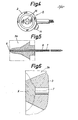
- the alloy portion X shown in Fig. 10 is basically formed in the same manner as shown in Fig. 5.
- a shorter insulating tube 8 is used.
- an oxide layer 7a is coated on an exterior of the pointed part of the heat-generating wire 7 in order to enhance insulation thereof furthermore.
- the alloy portion formed at the pointed part of the heat-generating means has an excellent wear resistance for flow of the fused synthetic resin, particularly a fused fiber- containing synthetic resin. And durability of the heat-generating means is extended remarkably. Further, since the alloy portion is formed at a small size by accurate cutting and processing, it is very suitable for molding precise plastic products. Further, since the heat capacity of the heat-generating means becomes lesser, the synthetic resin at the injection gate may be heated or cooled speedily.
Landscapes
- Engineering & Computer Science (AREA)
- Manufacturing & Machinery (AREA)
- Mechanical Engineering (AREA)
- Moulds For Moulding Plastics Or The Like (AREA)
- Injection Moulding Of Plastics Or The Like (AREA)
Applications Claiming Priority (2)
| Application Number | Priority Date | Filing Date | Title |
|---|---|---|---|
| JP88001/80U | 1980-06-25 | ||
| JP1980088001U JPS6112089Y2 (fr) | 1980-06-25 | 1980-06-25 |
Publications (2)
| Publication Number | Publication Date |
|---|---|
| EP0043234A1 true EP0043234A1 (fr) | 1982-01-06 |
| EP0043234B1 EP0043234B1 (fr) | 1983-10-26 |
Family
ID=13930537
Family Applications (1)
| Application Number | Title | Priority Date | Filing Date |
|---|---|---|---|
| EP81302849A Expired EP0043234B1 (fr) | 1980-06-25 | 1981-06-24 | Dispositif pointu générateur de chaleur pour moules de machines à mouler par injection |
Country Status (6)
| Country | Link |
|---|---|
| US (2) | US4516927A (fr) |
| EP (1) | EP0043234B1 (fr) |
| JP (1) | JPS6112089Y2 (fr) |
| AU (1) | AU547191B2 (fr) |
| CA (1) | CA1164615A (fr) |
| DE (1) | DE3161276D1 (fr) |
Cited By (11)
| Publication number | Priority date | Publication date | Assignee | Title |
|---|---|---|---|---|
| DE3335940A1 (de) * | 1983-10-04 | 1985-04-18 | EWIKON Entwicklung und Konstruktion GmbH & Co KG, 4900 Herford | Duese fuer eine kunststoffspritzgiessmaschine oder kunststoffspritzgiessform mit beheizbarer angussduese |
| US4516927A (en) * | 1980-06-25 | 1985-05-14 | Shigeru Tsutsume | Pointed heat-generating device for molds of injection molding machines |
| FR2569606A1 (fr) * | 1984-08-31 | 1986-03-07 | Tsutsumi Shigeru | Dispositif thermogene a pointe pour moules de machines de moulage par injection |
| US4642043A (en) * | 1983-07-09 | 1987-02-10 | Hotset Heizpatronen Und Zubehor Gmbh | Device for the electric heating and fluid cooling of an injection-molding machine nozzle |
| EP0162438A3 (en) * | 1984-05-25 | 1987-12-16 | Jobst Ulrich Gellert | Injection molding nozzle probe and stack molding apparatus |
| FR2604388A1 (fr) * | 1986-09-26 | 1988-04-01 | Sanri Kk | Dispositif generateur de chaleur, de forme pointue, presentant une grande sensibilite |
| EP0238355A3 (fr) * | 1986-03-21 | 1988-11-23 | Intelitec Corporation | Orifice d'injection thermique pour procédés de moulage de matières plastiques |
| EP0229689A3 (en) * | 1986-01-08 | 1988-12-21 | Fast Heat Element | Plastic injection moulding system with multiple tip torpedo heater |
| US4902219A (en) * | 1986-01-08 | 1990-02-20 | Fast Heat Element Manufacturing Company, Inc. | Plastic injection molding system with multiple tip torpedo heater |
| US4913912A (en) * | 1986-09-29 | 1990-04-03 | Fast Heat Element Manufacturing Co., Inc. | Plastic injection mold apparatus with multiple tip torpedo heater |
| GB2267863A (en) * | 1992-06-15 | 1993-12-22 | Seiki Kabushiki Kaisha | Temperature controlled valve gate for injection moulding |
Families Citing this family (16)
| Publication number | Priority date | Publication date | Assignee | Title |
|---|---|---|---|---|
| EP0165729B1 (fr) * | 1984-05-31 | 1989-03-01 | Toyota Jidosha Kabushiki Kaisha | Dispositif pour serrer une bobine sur un corps cylindrique |
| DE3545017C1 (de) * | 1985-07-19 | 1987-10-01 | Knauer Joachim Friedrich | Zwischen einer einen Formhohlraum begrenzenden Formplatte und einer Gegenplatte einer Kunststoff-Spritzgiessmaschine angeordnete Duesenpatrone |
| US4648833A (en) * | 1985-10-17 | 1987-03-10 | Fujio Yamada | Hot nozzle for runnerless mold |
| CA1267514A (fr) * | 1987-07-15 | 1990-04-10 | Jobst Ulrich Gellert | Buse d'injection a revetement pour le moulage |
| CA1263222A (fr) * | 1987-10-16 | 1989-11-28 | Jobst Ulrich Gellert | Methode de fabrication d'une buse de moulage par injection, son extremite pointue renfermant un element chauffant avec masse soude a meme |
| CA1261573A (fr) * | 1987-10-16 | 1989-09-26 | Harald H. Schmidt | Buse de moulage par injection a element chauffant mis a la masse, fixe a la pointe par brasage |
| CA1265909A (fr) * | 1988-02-16 | 1990-02-20 | Jobst Ulrich Gellert | Garniture sur guichet chauffe de moulage par injection, et methode connexe |
| CA1261576A (fr) * | 1988-04-13 | 1989-09-26 | Jobst U. Gellert | Buse de moulage par injection a element de chauffage multicouche et methode de fabrication |
| CA1261575A (fr) * | 1988-04-13 | 1989-09-26 | Jobst U. Gellert | Entree a obturateur pour moulage par injection a buses d'injection en tandem |
| US4931009A (en) * | 1989-06-12 | 1990-06-05 | Gellert Jobst U | Injection molding system having a thermal locating flange |
| JP2534609B2 (ja) * | 1993-02-16 | 1996-09-18 | 世紀株式会社 | 射出成形金型用プロ―ブおよびランナ―レス射出成形装置 |
| US5527177A (en) * | 1994-06-07 | 1996-06-18 | Potter; Edward J. | Tip heater for a runnerless injection molding probe |
| DE19606045C2 (de) * | 1996-02-19 | 1997-11-27 | Krupp Ag Hoesch Krupp | Verfahren zum Spritzgießen von dreischichtigen Spritzlingen und Vorrichtung für die Durchführung des Verfahrens |
| US6394784B1 (en) * | 2000-03-08 | 2002-05-28 | Mold-Masters Limited | Compact cartridge hot runner nozzle |
| US20050181090A1 (en) * | 2002-12-06 | 2005-08-18 | Mold-Masters Limited | Injection molding nozzle with embedded and removable heaters |
| WO2012015778A1 (fr) | 2010-07-29 | 2012-02-02 | Husky Injection Molding Systems Ltd | Ensemble moule-outil comprenant un dispositif de chauffage ayant un élément résistif incorporé dans du nitrure d'aluminium |
Citations (2)
| Publication number | Priority date | Publication date | Assignee | Title |
|---|---|---|---|---|
| FR2125496A1 (fr) * | 1971-02-17 | 1972-09-29 | Tsutsumi Shigeru | |
| US3911251A (en) * | 1973-11-05 | 1975-10-07 | Charles L Day | Heating device for molding |
Family Cites Families (7)
| Publication number | Priority date | Publication date | Assignee | Title |
|---|---|---|---|---|
| US3952927A (en) * | 1974-04-26 | 1976-04-27 | Standard Oil Company | Injection nozzle having guides for nozzle rod |
| JPS5932033B2 (ja) * | 1978-06-16 | 1984-08-06 | 株式会社東芝 | 工業用テレビカメラ |
| FR2459720A1 (fr) * | 1979-06-26 | 1981-01-16 | Solyvent Ventec Ste Lyon Venti | Ensemble de moule perfectionne pour le moulage des elastomeres |
| US4318686A (en) * | 1980-01-03 | 1982-03-09 | International Tools (1973) Limited | Injection molding apparatus for molding parts of thermosetting plastic material |
| JPS6112089Y2 (fr) * | 1980-06-25 | 1986-04-16 | ||
| CA1163073A (fr) * | 1981-05-08 | 1984-03-06 | Jobst U. Gellert | Sonde chauffee pour le moulage par injection |
| US4373132A (en) * | 1981-08-05 | 1983-02-08 | Haig Vartanian | External/internal heater for molding of plastics |
-
1980
- 1980-06-25 JP JP1980088001U patent/JPS6112089Y2/ja not_active Expired
-
1981
- 1981-06-19 US US06/275,230 patent/US4516927A/en not_active Expired - Lifetime
- 1981-06-22 AU AU72038/81A patent/AU547191B2/en not_active Ceased
- 1981-06-24 EP EP81302849A patent/EP0043234B1/fr not_active Expired
- 1981-06-24 CA CA000380511A patent/CA1164615A/fr not_active Expired
- 1981-06-24 DE DE8181302849T patent/DE3161276D1/de not_active Expired
-
1984
- 1984-11-30 US US06/676,582 patent/US4643664A/en not_active Expired - Lifetime
Patent Citations (3)
| Publication number | Priority date | Publication date | Assignee | Title |
|---|---|---|---|---|
| FR2125496A1 (fr) * | 1971-02-17 | 1972-09-29 | Tsutsumi Shigeru | |
| US3800027A (en) * | 1971-02-17 | 1974-03-26 | S Tsutsumi | Injection molding apparatus for synthetic resin |
| US3911251A (en) * | 1973-11-05 | 1975-10-07 | Charles L Day | Heating device for molding |
Cited By (14)
| Publication number | Priority date | Publication date | Assignee | Title |
|---|---|---|---|---|
| US4516927A (en) * | 1980-06-25 | 1985-05-14 | Shigeru Tsutsume | Pointed heat-generating device for molds of injection molding machines |
| US4642043A (en) * | 1983-07-09 | 1987-02-10 | Hotset Heizpatronen Und Zubehor Gmbh | Device for the electric heating and fluid cooling of an injection-molding machine nozzle |
| DE3335940A1 (de) * | 1983-10-04 | 1985-04-18 | EWIKON Entwicklung und Konstruktion GmbH & Co KG, 4900 Herford | Duese fuer eine kunststoffspritzgiessmaschine oder kunststoffspritzgiessform mit beheizbarer angussduese |
| EP0162438A3 (en) * | 1984-05-25 | 1987-12-16 | Jobst Ulrich Gellert | Injection molding nozzle probe and stack molding apparatus |
| DE3531127A1 (de) * | 1984-08-31 | 1986-03-13 | Shigeru Yonezawa Yamagata Tsutsumi | Zugespitzte waermeliefernde vorrichtung fuer formwerkzeuge von spritzgussmaschinen |
| US4704516A (en) * | 1984-08-31 | 1987-11-03 | Shigeru Tsutsumi | Pointed heat-generating device for molds of injection molding machines |
| FR2569606A1 (fr) * | 1984-08-31 | 1986-03-07 | Tsutsumi Shigeru | Dispositif thermogene a pointe pour moules de machines de moulage par injection |
| EP0229689A3 (en) * | 1986-01-08 | 1988-12-21 | Fast Heat Element | Plastic injection moulding system with multiple tip torpedo heater |
| US4902219A (en) * | 1986-01-08 | 1990-02-20 | Fast Heat Element Manufacturing Company, Inc. | Plastic injection molding system with multiple tip torpedo heater |
| EP0238355A3 (fr) * | 1986-03-21 | 1988-11-23 | Intelitec Corporation | Orifice d'injection thermique pour procédés de moulage de matières plastiques |
| FR2604388A1 (fr) * | 1986-09-26 | 1988-04-01 | Sanri Kk | Dispositif generateur de chaleur, de forme pointue, presentant une grande sensibilite |
| GB2196216B (en) * | 1986-09-26 | 1990-01-10 | Sanri Kk | Heat-generating device for local heating of injection moulding synthetic resin |
| US4913912A (en) * | 1986-09-29 | 1990-04-03 | Fast Heat Element Manufacturing Co., Inc. | Plastic injection mold apparatus with multiple tip torpedo heater |
| GB2267863A (en) * | 1992-06-15 | 1993-12-22 | Seiki Kabushiki Kaisha | Temperature controlled valve gate for injection moulding |
Also Published As
| Publication number | Publication date |
|---|---|
| CA1164615A (fr) | 1984-04-03 |
| US4643664A (en) | 1987-02-17 |
| AU7203881A (en) | 1982-01-07 |
| JPS5711017U (fr) | 1982-01-20 |
| JPS6112089Y2 (fr) | 1986-04-16 |
| DE3161276D1 (en) | 1983-12-01 |
| EP0043234B1 (fr) | 1983-10-26 |
| US4516927A (en) | 1985-05-14 |
| AU547191B2 (en) | 1985-10-10 |
Similar Documents
| Publication | Publication Date | Title |
|---|---|---|
| EP0043234A1 (fr) | Dispositif pointu générateur de chaleur pour moules de machines à mouler par injection | |
| US4376244A (en) | Injection molding heated probe | |
| US4954072A (en) | Electrically heated pin-point gate | |
| EP0307482B1 (fr) | Injecteur pour machines de moulage a injection | |
| US3911251A (en) | Heating device for molding | |
| US4940870A (en) | Induction heating apparatus for injection molding machine | |
| JP3004427B2 (ja) | テーパ付き加熱要素を有する射出成形ノズル | |
| EP0920969B1 (fr) | Dispositif de moulage par injection | |
| US4704516A (en) | Pointed heat-generating device for molds of injection molding machines | |
| JPH0559559B2 (fr) | ||
| DK0486968T3 (da) | Sprøjtestøbeapparat med et separat varmeelement i en forrumsindsats | |
| DE69507397D1 (de) | Heizbare Spritzgiessdüse mit Schützrohren | |
| ES2055814T3 (es) | Boquilla de inyeccion de moldeo con sondas conductoras separadas circularmente. | |
| US4721847A (en) | Multiple zoned runner distributor heater | |
| KR950012860B1 (ko) | 플라스틱 사출 성형 시스템 | |
| US5456592A (en) | Injection mold probe and runnerless injection mold | |
| CA2059960A1 (fr) | Aiguille d'injection a tube a thermocouple et element chauffants coaxiaux | |
| EP0336748A3 (fr) | Dispositif à mouler par injection les matières plastiques à torpille de chauffage à pointe multiple | |
| ES281644U (es) | Elemento de calentamiento que funcione electricamente. | |
| TW200810907A (en) | Heating cylinder for attachment to an injection nozzle for an injection molding system | |
| CN214983221U (zh) | 一种3d打印笔 | |
| JPH035112A (ja) | ランナーレス射出成形機における間欠加熱方法およびその装置 | |
| JPS6028569Y2 (ja) | 尖鋭発熱体 | |
| JPH0419007B2 (fr) | ||
| JPS58171932A (ja) | プラスチツク成形用射出口加熱装置 |
Legal Events
| Date | Code | Title | Description |
|---|---|---|---|
| PUAI | Public reference made under article 153(3) epc to a published international application that has entered the european phase |
Free format text: ORIGINAL CODE: 0009012 |
|
| 17P | Request for examination filed |
Effective date: 19810703 |
|
| AK | Designated contracting states |
Designated state(s): CH DE FR GB IT NL |
|
| GRAA | (expected) grant |
Free format text: ORIGINAL CODE: 0009210 |
|
| AK | Designated contracting states |
Designated state(s): CH DE FR GB IT LI NL |
|
| PG25 | Lapsed in a contracting state [announced via postgrant information from national office to epo] |
Ref country code: LI Effective date: 19831026 Ref country code: IT Free format text: LAPSE BECAUSE OF FAILURE TO SUBMIT A TRANSLATION OF THE DESCRIPTION OR TO PAY THE FEE WITHIN THE PRESCRIBED TIME-LIMIT;WARNING: LAPSES OF ITALIAN PATENTS WITH EFFECTIVE DATE BEFORE 2007 MAY HAVE OCCURRED AT ANY TIME BEFORE 2007. THE CORRECT EFFECTIVE DATE MAY BE DIFFERENT FROM THE ONE RECORDED. Effective date: 19831026 Ref country code: CH Effective date: 19831026 |
|
| REF | Corresponds to: |
Ref document number: 3161276 Country of ref document: DE Date of ref document: 19831201 |
|
| ET | Fr: translation filed | ||
| REG | Reference to a national code |
Ref country code: CH Ref legal event code: PL |
|
| PLBE | No opposition filed within time limit |
Free format text: ORIGINAL CODE: 0009261 |
|
| STAA | Information on the status of an ep patent application or granted ep patent |
Free format text: STATUS: NO OPPOSITION FILED WITHIN TIME LIMIT |
|
| 26N | No opposition filed | ||
| REG | Reference to a national code |
Ref country code: GB Ref legal event code: 732E |
|
| REG | Reference to a national code |
Ref country code: FR Ref legal event code: TP |
|
| NLS | Nl: assignments of ep-patents |
Owner name: SEIKI KABUSHIKI KAISHA TE TOKIO, JAPAN. |
|
| PGFP | Annual fee paid to national office [announced via postgrant information from national office to epo] |
Ref country code: NL Payment date: 19940630 Year of fee payment: 14 |
|
| PGFP | Annual fee paid to national office [announced via postgrant information from national office to epo] |
Ref country code: FR Payment date: 19950609 Year of fee payment: 15 |
|
| PG25 | Lapsed in a contracting state [announced via postgrant information from national office to epo] |
Ref country code: NL Effective date: 19960101 |
|
| NLV4 | Nl: lapsed or anulled due to non-payment of the annual fee |
Effective date: 19960101 |
|
| PGFP | Annual fee paid to national office [announced via postgrant information from national office to epo] |
Ref country code: DE Payment date: 19960627 Year of fee payment: 16 |
|
| PG25 | Lapsed in a contracting state [announced via postgrant information from national office to epo] |
Ref country code: FR Effective date: 19970228 |
|
| REG | Reference to a national code |
Ref country code: FR Ref legal event code: ST |
|
| PG25 | Lapsed in a contracting state [announced via postgrant information from national office to epo] |
Ref country code: DE Free format text: LAPSE BECAUSE OF NON-PAYMENT OF DUE FEES Effective date: 19980303 |
|
| PGFP | Annual fee paid to national office [announced via postgrant information from national office to epo] |
Ref country code: GB Payment date: 20000620 Year of fee payment: 20 |
|
| PG25 | Lapsed in a contracting state [announced via postgrant information from national office to epo] |
Ref country code: GB Free format text: LAPSE BECAUSE OF EXPIRATION OF PROTECTION Effective date: 20010623 |
|
| REG | Reference to a national code |
Ref country code: GB Ref legal event code: PE20 Effective date: 20010623 |