EP0045970A1 - Verfahren zur Bestimmung der Stromausbeute bei galvanischen Bädern - Google Patents
Verfahren zur Bestimmung der Stromausbeute bei galvanischen Bädern Download PDFInfo
- Publication number
- EP0045970A1 EP0045970A1 EP81106263A EP81106263A EP0045970A1 EP 0045970 A1 EP0045970 A1 EP 0045970A1 EP 81106263 A EP81106263 A EP 81106263A EP 81106263 A EP81106263 A EP 81106263A EP 0045970 A1 EP0045970 A1 EP 0045970A1
- Authority
- EP
- European Patent Office
- Prior art keywords
- current
- time
- electrode
- metal
- measuring cell
- Prior art date
- Legal status (The legal status is an assumption and is not a legal conclusion. Google has not performed a legal analysis and makes no representation as to the accuracy of the status listed.)
- Granted
Links
- 238000000034 method Methods 0.000 title claims description 31
- 238000009713 electroplating Methods 0.000 title 1
- 229910052751 metal Inorganic materials 0.000 claims abstract description 16
- 239000002184 metal Substances 0.000 claims abstract description 16
- 239000008151 electrolyte solution Substances 0.000 claims abstract description 11
- 238000001465 metallisation Methods 0.000 claims abstract description 4
- 238000005259 measurement Methods 0.000 claims description 6
- 238000004886 process control Methods 0.000 claims description 5
- 239000007788 liquid Substances 0.000 claims description 4
- 238000000151 deposition Methods 0.000 claims description 3
- 230000008021 deposition Effects 0.000 claims description 3
- 238000004140 cleaning Methods 0.000 claims description 2
- 238000012545 processing Methods 0.000 claims description 2
- 230000001105 regulatory effect Effects 0.000 claims description 2
- 239000000126 substance Substances 0.000 claims 1
- 238000005137 deposition process Methods 0.000 abstract description 2
- 239000003792 electrolyte Substances 0.000 description 6
- 230000005611 electricity Effects 0.000 description 3
- XLYOFNOQVPJJNP-UHFFFAOYSA-N water Substances O XLYOFNOQVPJJNP-UHFFFAOYSA-N 0.000 description 2
- RTAQQCXQSZGOHL-UHFFFAOYSA-N Titanium Chemical compound [Ti] RTAQQCXQSZGOHL-UHFFFAOYSA-N 0.000 description 1
- 238000004458 analytical method Methods 0.000 description 1
- 230000015572 biosynthetic process Effects 0.000 description 1
- 229940075397 calomel Drugs 0.000 description 1
- 230000001419 dependent effect Effects 0.000 description 1
- ZOMNIUBKTOKEHS-UHFFFAOYSA-L dimercury dichloride Chemical compound Cl[Hg][Hg]Cl ZOMNIUBKTOKEHS-UHFFFAOYSA-L 0.000 description 1
- 238000005868 electrolysis reaction Methods 0.000 description 1
- 238000011156 evaluation Methods 0.000 description 1
- 238000012544 monitoring process Methods 0.000 description 1
- 229910000510 noble metal Inorganic materials 0.000 description 1
- 238000000926 separation method Methods 0.000 description 1
- 239000010936 titanium Substances 0.000 description 1
- 229910052719 titanium Inorganic materials 0.000 description 1
- 239000002699 waste material Substances 0.000 description 1
Images
Classifications
-
- C—CHEMISTRY; METALLURGY
- C25—ELECTROLYTIC OR ELECTROPHORETIC PROCESSES; APPARATUS THEREFOR
- C25D—PROCESSES FOR THE ELECTROLYTIC OR ELECTROPHORETIC PRODUCTION OF COATINGS; ELECTROFORMING; APPARATUS THEREFOR
- C25D21/00—Processes for servicing or operating cells for electrolytic coating
- C25D21/12—Process control or regulation
Definitions
- the invention relates to a method for determining the current efficiency in galvanic baths.
- the invention has for its object to provide a method for determining the current efficiency in a galvanic bath.
- the automatic determination of the current yield in conjunction with a corresponding control enables constant layer thicknesses to be maintained, in particular in the case of continuous galvanic systems.
- a bath sample is taken from the galvanic bath and from this in a measuring cell under the influence of a negative DC voltage at constant current i k for a predetermined time t k on a preferably rotating electrode metal is deposited, that subsequently layer deposited by means of a suitable electrolyte solution to pole reversal of the DC voltage at a constant current i a and a to be determined time t is a anodically removed and that the current efficiency according to the formula k is calculated in which ya means the current efficiency of the anodic removal.
- the time for anodic removal of the deposited metal is preferably determined from the potential-time curve.
- the potential between the rotating electrode and a reference electrode is recorded, which has a constant voltage.
- the time for anodic removal is determined by at least two measurements with different distances between the rotating electrode and the counter electrode.
- All of the components required for the automatic implementation of the method and / or the processing of measured values are preferably controlled by a process control circuit.
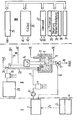
- the method according to the invention is explained in more detail with reference to the drawing.
- the drawing shows an arrangement for automatically measuring the current efficiency in principle.
- I denotes a process part which contains a galvanic bath 1 as the most important part in which the process electrolyte is located. It is assumed that the galvanic bath is a continuous galvanic system.
- the boxes labeled 3 and 4 are intended to indicate that a defined current density (or current) and a specific belt speed can be specified in order to achieve a specific layer thickness, as indicated by a dashed arrow 5. Such systems are known per se and do not form the subject of this invention.
- thermostatted measuring cell 6 which can be supplied with a defined amount of electrolyte solution from the galvanic bath 1 by means of a metering syringe 7 via a valve 8 and a line 9.
- the measuring cell 7 has a rotating electrode 10, a counter electrode 11 opposite it and a reference electrode 12 as the working electrode.
- the working electrode 10 carries a metal disc 13 at the lower end, which faces the counter electrode 11.
- the reference electrode 12 is conventional and can be, for example, a calomel, Ag or AgCL electrode.
- the counterelectrode 11 can, for example, be a platinized titanium sheet, or it is adapted to the respective measurement problem, as is the metal disk 13 of the working electrode 10.
- the electromotive drive of the rotating working electrode 10 is designated by 14, which is connected via lines 15 and 16 to an electronic part III is related, as will be described in more detail below.
- a pipe 18 is connected, for example leads to a waste bin.
- Another outlet of the three-way valve 18 is connected to the galvanic bath 1 via a pipeline 19 so that the bath sample located in the measuring cell 6 can be returned to the galvanic bath 1, which is particularly important when using a noble metal electrolyte.
- the electronic part III contains a control part 25 for the rotating working electrode 10, the output Ant of which is connected to the connection of the line 15 which is identified by the same name.
- the rotational speed of the working electrode 10 can be predetermined via the control part 25.
- a potentiograph is designated, which serves to record the potential-time curve.
- the outputs of the potentiograph 26 labeled AE and BE are connected to the correspondingly labeled connections AE and BE of the working electrode 10 and the reference electrode 12, respectively.
- the working electrode 10 and the counter electrode 11 lie in a circuit which can be supplied with constant current by a current source 27.
- the outputs AE and GE of the current source 27 are connected to the correspondingly labeled connections of the working electrode 10 and the counter electrode 11.
- the electronic part III also contains a process control circuit 28 with a microprocessor 29 and a control panel 30. Furthermore, the entire system is included a regulation 31 equipped. For example, the speed of rotation of the working electrode 10 of the desired current density, ie that of the electrolyte to be examined, can be set and controlled by the microprocessor 29. Furthermore, the entire sequence of the measuring process and the regulation of the current density and the belt speed of the galvanic bath can be controlled by the same microprocessor 29.
- the rotating working electrode 10 is used to increase and keep the mass transport constant.
- the setting of the corresponding speed of rotation of the working electrode and the current density i k are controlled by the microprocessor 29.
- the current is switched off and the bath sample from the measuring cell 6 is returned to the galvanic bath 1 via the three-way valve 17 and line 19.
- the process control 28 then rinses the measuring cell 6 with water via valve 24 and drains it off via line 18.
- a defined amount of electrolyte solution is then introduced from the electrolyte container 22 into the measuring cell 6 with the aid of the metering syringe 21.
- This electrolyte solution is adapted to the metal deposit; however, it is intended to enable a constant, if possible 100% current yield when removing the metal deposited on the metal disk 13 of the working electrode 10.
- the potentials on the working electrode 10 and on the counter electrode 11 are reversed, the anodic current i a and the optimum rotational speed of the working electrode 10 being adjusted using the microprocessor 29.
- the temperature is also kept constant during anodic removal. For procedural reasons, it can be kept lower, for example to avoid steam formation.
- the potential-time data are continuously stored in the microprocessor 29 and the end point is determined therefrom.
- the potential profile between the working electrode 10 and the reference electrode 12 can be recorded during the removal.
- the end point of the metal removal results in the time t a and is indicated in the potential-time curve by a strong change in potential.
- the current supply to the electrodes is caused to be switched off; the measuring cell is then emptied and rinsed and prepared for a new measurement.
- the working electrode may have to be cleaned of remaining deposits. A corresponding other liquid is used for this.
- the amount of electricity required for removal is equal to i a xtxy a , where y a is the anodic current yield.
- y a the anodic current yield.
- the current density in the galvanic bath and / or the exposure time is preferably regulated as a function of the current yield (y k ).
- the evaluation of the potential-time curve for determining t a can be carried out in a manner known per se, for example by the intersection of straight lines through linear sections of the curve or a turning point in the case of an S-shaped curve.
- the scattering of an electrolyte can also be determined with the method according to the invention.
- Scattering means the fluctuating layer thickness occurring on a part to be electroplated if the distance between the surface of the part and the anode is not the same.
- at least two measurements with different distances between the rotating electrode 10 and the counter electrode 11 must be carried out to determine the scatter.
- two mutually independent measuring cells with different distances between the rotating electrode and the counter electrode are used to determine the scatter.
- Two y k values are calculated from this; The relationship these two values is a measure of the spread.
- a rotating electrode which carries several suitable metal disks at the lower end, e.g. 2 for the ring-disc electrode and 3 for a split ring-disc electrode (i.e. the so-called split-ring-disc electrode).
- Two or more y k values are calculated from this; the ratio of these values is a measure of the spread.
- the measuring principle according to the invention is not limited to the direct voltage method, but can e.g. can also be used for pulse separation.
Landscapes
- Engineering & Computer Science (AREA)
- Chemical & Material Sciences (AREA)
- Automation & Control Theory (AREA)
- Chemical Kinetics & Catalysis (AREA)
- Electrochemistry (AREA)
- Materials Engineering (AREA)
- Metallurgy (AREA)
- Organic Chemistry (AREA)
- Investigating Or Analyzing Materials By The Use Of Electric Means (AREA)
- Electroplating Methods And Accessories (AREA)
- Electrolytic Production Of Metals (AREA)
Abstract
Description
- Die Erfindung bezieht sich auf ein Verfahren zur Bestimmung der Stromausbeute bei galvanischen Bädern.
- Bei der Metallabscheidung führen Schwankungen in der Stromausbeute zu Schwankungen in der Schichtdicke, vor allem, wenn beim Abscheidungsprozess lediglich nach Stromdichte und Expositionszeit (Amperestundenzahl) gearbeitet wird. Die Stromausbeute ist nicht nur vom Gehalt der Badkomponenten sondern auch von einer ganzen Reihe von Einflußgrößen abhängig, die nicht mit den üblichen analytischen Verfahren erfassbar sind. Daher sind reine Amperestundenzahlen und die übliche analytische Überwachung des Bades keine ausreichenden Kriterien für die Konstanthaltung der Schichtdicke. Für die Konstanthaltung einer bestimmten Schichtdicke ist vielmehr das Produkt i x t x y maßgebend, wobei i den Strom (bzw. die Stromdichte), t die Expositionszeit und y die Stromausbeute bedeuten.
- Der Erfindung liegt die Aufgabe zugrunde, ein Verfahren zur Bestimmung der Stromausbeute bei einem galvanischen Bad zu schaffen. Insbesondere die automatische Bestimmung der Stromausbeute in Verbindung mit einer entsprechenden Regelung ermöglicht das Einhalten von konstanten Schichtdicken, insbesondere bei galvanischen Durchlaufanlagen.
- Gemäß der Erfindung besteht das Verfahren zur Bestimmung der Stromausbeute bei galvanischen Bädern darin, daß dem galvanischen Bad eine Badprobe entnommen wird und aus dieser in einer Meßzelle unter dem Einfluß einer negativen Gleichspannung bei konstantem Strom ik während einer vorgegebenen Zeit tk auf einer vorzugsweise rotierenden Elektrode Metall abgeschieden wird, daß nachfolgend die abgeschiedene Schicht mit Hilfe einer geeigneten Elektrolytlösung unter Umpolung der Gleichspannung bei konstantem Strom ia und in einer zu ermittelnden Zeit ta anodisch abgetragen wird und daß die Stromausbeute k nach der Formel

- Vorzugsweise wird die Zeit zum anodischen Abtragen des abgeschiedenen Metalls aus der Potential-Zeit-Kurve ermittelt. Hierbei wird zur Aufnahme der Potential-Zeit-Kurve das Potential zwischen rotierender Elektrode und einer Bezugselektrode erfaßt, welche eine konstante Spannung aufweist.
- Zur Ermittlung der Streuung wird die Zeit zum anodischen Abtragen durch mindestens zwei Messungen mit verschiedenen Abständen zwischen der rotierenden Elektrode und der Gegenelektrode ermittelt.
- Vorzugsweise erfolgt die Steuerung sämtlicher für die automatische Durchführung des Verfahrens erforderlichen Bauteile und/oder die Meßwertverarbeitung von einer Prozeßsteuerschaltung.
- Anhand der Zeichnung wird das erfindungsgemäße Verfahren näher erläutert. Die Zeichnung zeigt eine Anordnung zum automatischen Messender Stromausbeute im Prinzip.
- Mit I ist ein Prozeßteil bezeichnet, der ein galvanisches Bad 1 als wesentlichsten Teil enthält, in welchem sich der Prozeßelektrolyt befindet. Es ist angenommen, daß es sich bei dem galvanischen Bad um eine galvanische Durchlaufanlage handelt. Durch die mit 3 und 4 bezeichneten Kästchen soll angedeutet werden, daß zur Erzielung einer bestimmten Schichtdicke eine definierte Stromdichte (bzw. Strom) und eine bestimmte Bandgeschwindigkeit vorgebbar sind, wie durch einen gestrichelten Pfeil 5 angedeutet ist. Derartige Anlagen sind ansich bekannt und bilden nicht Gegenstand dieser Erfindung.
- Mit II ist ein Meßteil zur Erfassung der für die Bestimmung der Stromausbeute maßgebenden Größen bezeichnet. Er enthält eine thermostatisierte Meßzelle 6, der mit Hilfe einer Dosierspritze 7 über ein Ventil 8 und eine Leitung 9 eine definierte Menge Elektrolytlösung aus dem galvanischen Bad 1 zuführbar ist.
- Die Meßzelle 7 weist als Arbeitselektrode eine rotierende Elektrode 10, eine dieser gegenüberstehende Gegenelektrode 11 und eine Bezugselektrode 12 auf. Die Arbeitselektrode 10 trägt am unteren Ende eine Metallscheibe 13, die der Gegenelektrode 11 gegenübersteht. Die Bezugselektrode 12 ist herkömmlicher Art und kann beispielsweise eine Kalomel-, Ag- oder AgCL-Elektrode sein. Die Gegenelektrode 11 kann beispielsweise ein platiniertes Titanblech sein, bzw. sie ist dem jeweiligen Meßproblem angepaßt, wie auch die Metallscheibe 13 der Arbeitselektrode 10. Mit 14 ist der elektromotorische Antrieb der rotierenden Arbeitselektrode 10 bezeichnet, der über Leitungen 15 und 16 mit einem Elektronikteil III in Verbindung steht, wie weiter unten noch näher beschrieben wird.
- Am unteren Ende der Meßzelle 6 befindet sich ein vorzugsweise automatisch betätigbarer Dreiwegehahn 17, an dem eine Rohrleitung 18 angeschlossen ist, die beispielsweise zu einem Abfallbehälter führt. Ein weiterer Ausgang des Dreiwegehahns 18 ist über eine Rohrleitung 19 mit dem galvanischen Bad 1 verbunden, damit die in der Meßzelle 6 befindliche Badprobe in das galvanische Bad 1 zurückgeführt werden kann, was insbesondere bei Verwendung eines Edelmetall-Elektrolyten von Bedeutung ist.
- Mit 20 ist ein Elektrolytbehälter bezeichnet, in dem sich eine geeignete Elektrolytlösung befindet, die mit Hilfe einer Dosierspritze 21 über eine Rohrleitung 22 ebenfalls der Meßzelle 6 zugeführt werden kann. Ferner kann über eine Rohrleitung 23 und Ventil 24 der Meßzelle 6 Wasser oder eine andere Flüssigkeit zum Spülen und Reinigen zugeführt werden.
- Der Elektronikteil III enthält einen Steuerungsteil 25, für die rotierende Arbeitselektrode 10, dessen Ausgang Ant mit dem gleich bezeichneten Anschluß der Leitung 15 in Verbindung steht. Über den Steuerungsteil 25 kann die Drehgeschwindigkeit der Arbeitselektrode 10 vorgegeben werden. Mit 26 ist ein Potentiograph bezeichnet, der zur Aufnahme der Potential-Zeit-Kurve dient. Die mit AE und BE bezeichneten Ausgänge des Potentiographen 26 sind mit den entsprechend bezeichneten Anschlüssen AE und BE der Arbeitselektrode 10 bzw. der Bezugselektrode 12 verbunden.
- Die Arbeitselektrode 10 und die Gegenelektrode 11 liegen in einem Stromkreis, der von einer Stromquelle 27 mit konstantem Strom versorgt werden kann. Die Ausgänge AE und GE der Stromquelle 27 sind mit den entsprechend bezeichneten Anschlüssen der Arbeitselektrode 10 bzw. der Gegenelektrode 11 verbunden.
- Schließlich enthält der Elektronikteil III noch eine Prozeßsteuerschaltung 28 mit einem Mikroprozessor 29 sowie einem Bedienfeld 30. Ferner ist die ganze Anlage mit einer Regelung 31 ausgestattet. So kann beispielsweise die Rotationsgeschwindigkeit der Arbeitselektrode 10 der gewünschten Stromdichte, d.h. dem zur untersuchenden Elektrolyten von dem Mikroprozessor 29 eingestellt und gesteuert werden. Ferner kann der ganze Ablauf des Meßvorgangs und die Regelung der Stromdichte und der Bandgeschwindigkeit des galvanischen Bades von dem selben Mikroprozessor 29 gesteuert sein.
- Der Meßzyklus besteht aus folgenden Schritten:
- Mit Hilfe der Dosierspritze 7 wird eine definierte Menge Elektrolytlösung dem galvanischen Bad 1 entnommen und diese Badprobe in die thermostatisierte Meßzelle 6 eingebracht. Hierbei wird die Temperatur in der Meßzelle beim Abscheiden gleich der Temperatur in dem galvanischen Bad 1 gehalten.
- Mit einem konstanten Strom ik (bzw. Stromdichte jk), der möglichst genau der Stromdichte in dem galvanischen Bad 1 entspricht, wird während einer vorgegebenen Zeit tk Metall abgeschieden. Das Produkt ik x tk entspricht der zugeführten Elektrizitätsmenge (Amperestundenzahl). In der Praxis wird jedoch nur ein Teil yk von dieser gesamten Blektrizitätsmenge für die eigentliche Metallabscheidung verbraucht; daher ist die Größe yk die für den vorliegenden Prozeß gesuchte Stromausbeute.
- Die Aussagekraft der automatischen Bestimmung der Stromausbeute in der Meßzelle 6 wird desto größer sein je genauer der Prozessablauf im galvanischen Bad 1 in der Meßzelle 6 simuliert wird.
- Um große Stromdichten in der Meßzelle verwenden zu können, wie sie z.B. in Durchlaufanlagen üblich sind, wird zur Steigerung und Konstanthaltung des Stofftransportes die rotierende Arbeitselektrode 10 eingesetzt. Die Einstellung der entsprechenden Drehgeschwindigkeit der Arbeitselektrode und der Stromdichte ik werden von dem Mikroprozessor 29 gesteuert. Sobald die eingestellte Elektrolyse-Zeit tk erreicht ist, wird der Strom abgeschaltet und die Badprobe aus der Meßzelle 6 über den Dreiwegehahn 17 und Leitung 19 wieder dem galvanischen Bad 1 zugeführt. Anschließend wird von der Prozeßsteuerung 28 über Ventil 24 die Meßzelle 6 mit Wasser gespült und dieses über Leitung 18 abgeleitet.
- Danach wird mit Hilfe der Dosierspritze 21 eine definierte Menge Elektrolytlösung aus dem Elektrolytbehälter 22 in die Meßzelle 6 eingebracht. Diese Elektrolytlösung wird dem Metallniederschlag angepaßt; sie soll jedoch eine konstante, möglichst 100%-ige Stromausbeute beim Abtragen des auf der Metallscheibe 13 der Arbeitselektrode 10 abgeschiedenen Metalls ermöglichen. Die Potentiale an der Arbeitselektrode 10 und an der Gegenelektrode 11 werden umgepolt, wobei mit Hilfe des Mikroprozessors 29 der anodische Strom ia und die zum Abtragen optimale Rotationsgeschwindigkeit der Arbeitselektrode 10 eingestellt werden. Während des anodischen Abtragens wird die Temperatur ebenfalls konstant gehalten. Sie kann aus verfahrenstechnischen Gründen niedriger gehalten werden, um z.B. Dampfbildung zu vermeiden.
- Zur Aufnahme der Potential-Zeit-Kurve werden die Potential-Zeitdaten laufend im Mikroprozessor 29 eingespeichert und daraus der Endpunkt ermittelt. Mit Hilfe des Potentiographen 26 kann der Potentialverlauf zwischen Arbeitselektrode 10 und Bezugselektrode 12 während der Abtragung aufgenommen werden. Der Endpunkt der Metallabtragung ergibt die Zeit ta und wird in der Potential-Zeit-Kurve durch eine starke Potentialänderung angezeigt. Nach Bestimmung des Endpunktes wird veranlaßt, daß die Stromzufuhr zu den Elektroden abgeschaltet wird; danach wird die Meßzelle entleert und gespült und für eine neue Messung vorbereitet.
- Unter Umständen muß die Arbeitselektrode von restlichen Abscheidungen gereinigt werden. Hierzu wird eine entsprechende andere Flüssigkeit verwendet.
- Die zum Abtragen benötigte Elektrizitätsmenge ist gleich i a x t x ya, wobei y a die anodische Stromausbeute ist. Durch geeignete Wahl der Elektrolytlösung, kann die anodische Stromaasbeate y a = 1 gehalten werden. Die Stromausbeute kann nun mit Hilfe des Mikroprozessors 29 auf folgende Weise berechnet werden:

- Dieser Wert kann zusammen mit der eingestellten Stromdichte und Rotätionsgeschwindigkeit protokolliert werden. Vorzugsweise wird die Stromdichte im galvanischen Bad und/oder die Expositionszeit in Abhängigkeit von der Stromausbeute (yk) geregelt.
- Die Auswertung der Potential-Zeit-Kurve zur Bestimmung von ta kann in an sich bekannter Weise vorgenommen werden, beispielsweise durch den Schnittpunkt von Geraden durch lineare Abschnitte der Kurve oder einen Wendepunkt bei S-förmigem Kurvenverlauf.
- Mit dem erfindungsgemäßen Verfahren kann auch die Streuung eines Elektrolyten bestimmt werden. Unter der Streuung versteht man die an einem zu galvanisierenden Teil auftretende schwankende Schichtdicke, wenn die Entfernung zwischen der Oberfläche des Teiles und der Anode nicht gleich ist. Zur Ermittlung der Streuung sind gemäß einem weiteren Merkmal mindestens zwei Messungen mit verschiedenen Abständen zwischen der rotierenden Elektrode 10 und der Gegenelektrode 11 vorzunehmen. Vorzugsweise werden zur Ermittlung der Streuung zwei voneinander unabhängige Meßzellen mit unterschiedlichen Abständen zwischen der rotierenden Elektrode und der Gegenelektrode verwendet. Daraus werden zwei y k - Werte errechnet; das Verhältnis dieser beiden Werte ist ein Maß für die Streuung.
- Vorzugsweise wird zur Ermittlung der Streuung im obengenannten Zweizellensystem oder in einer einzigen Zelle, eine rotierende Elektrode verwendet, welche am unteren Ende mehrere geeignete Metallscheiben trägt, z.B. 2 für die Ring-Scheibe Elektrode und 3 für eine gespaltete Ring-Scheibe Elektrode (d.h. die sog. Split-ring-disc electrode).
- Daraus werden zwei oder mehrere yk-Werte errechnet; das Verhältnis dieser Werte ist ein Maß für die Streuung.
- Das erfindungsgemäße Meßprinzip ist nicht beschränkt auf das Gleichspannungsverfahren, sondern kann z.B. auch für die Pulsabscheidung eingesetzt werden.
Claims (17)

Applications Claiming Priority (2)
| Application Number | Priority Date | Filing Date | Title |
|---|---|---|---|
| DE3030664A DE3030664C2 (de) | 1980-08-13 | 1980-08-13 | Verfahren zur Bestimmung der Stromausbeute bei galvanischen Bädern |
| DE3030664 | 1980-08-13 |
Publications (2)
| Publication Number | Publication Date |
|---|---|
| EP0045970A1 true EP0045970A1 (de) | 1982-02-17 |
| EP0045970B1 EP0045970B1 (de) | 1985-01-16 |
Family
ID=6109561
Family Applications (1)
| Application Number | Title | Priority Date | Filing Date |
|---|---|---|---|
| EP81106263A Expired EP0045970B1 (de) | 1980-08-13 | 1981-08-11 | Verfahren zur Bestimmung der Stromausbeute bei galvanischen Bädern |
Country Status (5)
| Country | Link |
|---|---|
| US (1) | US4595462A (de) |
| EP (1) | EP0045970B1 (de) |
| JP (1) | JPS5754849A (de) |
| CA (1) | CA1166187A (de) |
| DE (1) | DE3030664C2 (de) |
Cited By (2)
| Publication number | Priority date | Publication date | Assignee | Title |
|---|---|---|---|---|
| DE102008061877B3 (de) * | 2008-12-11 | 2010-09-02 | Fraunhofer-Gesellschaft zur Förderung der angewandten Forschung e.V. | Vorrichtung zur Bestimmung von Prozessbedingungen bei der elektrochemischen Beschichtung eines Profilkörpers und Verfahren |
| EP2495357A2 (de) | 2010-11-25 | 2012-09-05 | Technische Universität Dresden | Einrichtung und Verfahren zur Messung der Geschwindigkeit oder der Stromausbeute bei der Abscheidung oder beim Abtrag von Oberflächen und zur darauf basierenden Prozesssteuerung |
Families Citing this family (21)
| Publication number | Priority date | Publication date | Assignee | Title |
|---|---|---|---|---|
| GB8408113D0 (en) * | 1984-03-29 | 1984-05-10 | Quantel Ltd | Video editing/viewing systems |
| US4917774A (en) * | 1986-04-24 | 1990-04-17 | Shipley Company Inc. | Method for analyzing additive concentration |
| US4956610A (en) * | 1988-02-12 | 1990-09-11 | Pgm Diversified Industries, Inc. | Current density measurement system by self-sustaining magnetic oscillation |
| US5059908A (en) * | 1990-05-31 | 1991-10-22 | Capital Controls Company, Inc. | Amperimetric measurement with cell electrode deplating |
| CA2087801C (en) * | 1993-01-21 | 1996-08-13 | Noranda Ipco Inc. | Method and apparatus for on-line monitoring the quality of a purified metal sulphate solution |
| US6269533B2 (en) * | 1999-02-23 | 2001-08-07 | Advanced Research Corporation | Method of making a patterned magnetic recording head |
| US6496328B1 (en) | 1999-12-30 | 2002-12-17 | Advanced Research Corporation | Low inductance, ferrite sub-gap substrate structure for surface film magnetic recording heads |
| US20040040842A1 (en) * | 2002-09-03 | 2004-03-04 | King Mackenzie E. | Electrochemical analytical apparatus and method of using the same |
| US6986835B2 (en) * | 2002-11-04 | 2006-01-17 | Applied Materials Inc. | Apparatus for plating solution analysis |
| US20050067304A1 (en) * | 2003-09-26 | 2005-03-31 | King Mackenzie E. | Electrode assembly for analysis of metal electroplating solution, comprising self-cleaning mechanism, plating optimization mechanism, and/or voltage limiting mechanism |
| US20050109624A1 (en) * | 2003-11-25 | 2005-05-26 | Mackenzie King | On-wafer electrochemical deposition plating metrology process and apparatus |
| US20050224370A1 (en) * | 2004-04-07 | 2005-10-13 | Jun Liu | Electrochemical deposition analysis system including high-stability electrode |
| US6984299B2 (en) * | 2004-04-27 | 2006-01-10 | Advanced Technology Material, Inc. | Methods for determining organic component concentrations in an electrolytic solution |
| US7435320B2 (en) | 2004-04-30 | 2008-10-14 | Advanced Technology Materials, Inc. | Methods and apparatuses for monitoring organic additives in electrochemical deposition solutions |
| US7427346B2 (en) * | 2004-05-04 | 2008-09-23 | Advanced Technology Materials, Inc. | Electrochemical drive circuitry and method |
| WO2005124335A1 (en) * | 2004-06-11 | 2005-12-29 | Carnegie Mellon University | Apparatus and method for determining the zeta potential of surfaces and for the measurement of streaming metrics related thereto |
| US7851222B2 (en) * | 2005-07-26 | 2010-12-14 | Applied Materials, Inc. | System and methods for measuring chemical concentrations of a plating solution |
| US20070261963A1 (en) * | 2006-02-02 | 2007-11-15 | Advanced Technology Materials, Inc. | Simultaneous inorganic, organic and byproduct analysis in electrochemical deposition solutions |
| DE102015106432A1 (de) | 2015-04-27 | 2016-10-27 | Gramm Technik Gmbh | Verfahren und Vorrichtung zur Herstellung eines Werkstücks |
| CN106199199B (zh) * | 2016-09-30 | 2017-06-16 | 山东齐星新能源科技有限责任公司 | 一种软包装锂离子电池铝塑膜腐蚀的检测方法 |
| US10329683B2 (en) * | 2016-11-03 | 2019-06-25 | Lam Research Corporation | Process for optimizing cobalt electrofill using sacrificial oxidants |
Family Cites Families (7)
| Publication number | Priority date | Publication date | Assignee | Title |
|---|---|---|---|---|
| US3215609A (en) * | 1962-12-04 | 1965-11-02 | Conversion Chem Corp | Electroplating test cell and method |
| DE1935231C3 (de) * | 1969-07-11 | 1979-04-05 | Fernsteuergeraete Kurt Oelsch Kg, 1000 Berlin | Verfahren zur Bestimmung der Stromansbeute elektrolytischer Bäder |
| US4132605A (en) * | 1976-12-27 | 1979-01-02 | Rockwell International Corporation | Method for evaluating the quality of electroplating baths |
| US4102770A (en) * | 1977-07-18 | 1978-07-25 | American Chemical And Refining Company Incorporated | Electroplating test cell |
| US4153521A (en) * | 1977-08-05 | 1979-05-08 | Litvak Rafael S | Method of automatic control and optimization of electrodeposition conditions |
| US4229264A (en) * | 1978-11-06 | 1980-10-21 | The Boeing Company | Method for measuring the relative etching or stripping rate of a solution |
| US4310389A (en) * | 1980-06-16 | 1982-01-12 | Chrysler Corporation | Method for simultaneous determination of thickness and electrochemical potential in multilayer plated deposits |
-
1980
- 1980-08-13 DE DE3030664A patent/DE3030664C2/de not_active Expired
-
1981
- 1981-07-16 US US06/284,100 patent/US4595462A/en not_active Expired - Fee Related
- 1981-08-11 CA CA000383649A patent/CA1166187A/en not_active Expired
- 1981-08-11 EP EP81106263A patent/EP0045970B1/de not_active Expired
- 1981-08-13 JP JP56127320A patent/JPS5754849A/ja active Granted
Non-Patent Citations (1)
| Title |
|---|
| Das Buch "Galvanotechnik" W. VON PFANHAUSER , Band I, Leipzig 1941, Akademische Verlagsgesellschaft, Seiten 18-20 * |
Cited By (2)
| Publication number | Priority date | Publication date | Assignee | Title |
|---|---|---|---|---|
| DE102008061877B3 (de) * | 2008-12-11 | 2010-09-02 | Fraunhofer-Gesellschaft zur Förderung der angewandten Forschung e.V. | Vorrichtung zur Bestimmung von Prozessbedingungen bei der elektrochemischen Beschichtung eines Profilkörpers und Verfahren |
| EP2495357A2 (de) | 2010-11-25 | 2012-09-05 | Technische Universität Dresden | Einrichtung und Verfahren zur Messung der Geschwindigkeit oder der Stromausbeute bei der Abscheidung oder beim Abtrag von Oberflächen und zur darauf basierenden Prozesssteuerung |
Also Published As
| Publication number | Publication date |
|---|---|
| DE3030664A1 (de) | 1982-03-18 |
| EP0045970B1 (de) | 1985-01-16 |
| JPS5754849A (en) | 1982-04-01 |
| CA1166187A (en) | 1984-04-24 |
| JPH021262B2 (de) | 1990-01-10 |
| US4595462A (en) | 1986-06-17 |
| DE3030664C2 (de) | 1982-10-21 |
Similar Documents
| Publication | Publication Date | Title |
|---|---|---|
| EP0045970B1 (de) | Verfahren zur Bestimmung der Stromausbeute bei galvanischen Bädern | |
| DE69534714T2 (de) | Verfahren und vorrichtung zum steuern der zufuhr von wasserbehandlungschemikalien unter verwendung eines voltametrischen sensors | |
| DE69121473T2 (de) | Strommessung mit Entfernen der galvanischen Schicht an den Elektroden einer Zelle | |
| DE3010750C2 (de) | ||
| DE2757458C2 (de) | ||
| DE3736429C2 (de) | Verfahren zur steuerung von stromlos metall abscheidenden badloesungen | |
| DE2837219C2 (de) | ||
| DE2521282B1 (de) | Prozessteueranlage zum selbsttaetigen analysieren und auffrischen von galvanischen baedern | |
| DE3785752T2 (de) | Verfahren und vorrichtung zur feststellung von elektrochemisch aktiven bestandteilen in einem prozessstrom. | |
| DE3783831T2 (de) | Verfahren und vorrichtung zur kontrolle des organischen kontaminationspegels in einem platierungsbad ohne elektrode. | |
| DE2729115A1 (de) | Verfahren und vorrichtung zur bestimmung der effektiven konzentration eines elektroaktiven bestandteils | |
| DE69318932T2 (de) | Verfahren zur selektiven Überwachung von Spurenbestandteilen in Plattierungsbädern | |
| DE2711989B1 (de) | Elektrochemische Bestimmung von Schwermetallen in Wasser | |
| DE2352040A1 (de) | Verfahren und vorrichtung zur selektiven loesung eines metalls | |
| DE69734221T2 (de) | Verfahren und Vorrichtung zur elektrochemischen Feinbearbeitung von Materialien | |
| DE69423018T2 (de) | Verfahren zur Überwachung einer Reinigungsbehandlung in Plattierungbädern | |
| EP2605007B2 (de) | Verfahren zum Reinigen von Elektrodenoberflächen | |
| DE3884447T2 (de) | In-situ-Überwachung der Korrosionsrate von polarisierten oder unpolarisierten Metallen. | |
| DE19911447A1 (de) | Verfahren zum analytischen Ermitteln der Konzentration von Zusatzstoffen in galvanischen Metallabscheidebädern | |
| DE69401984T2 (de) | Verfahren und Vorrichtung zur elektrolytischen Silberrückgewinnung in zwei Filmentwicklungsmaschinen | |
| EP0022503B1 (de) | Vorrichtung zur Anzeige der metallspezifischen Beladung von Ionenaustauschern | |
| DE3050290A1 (de) | Verfahren zur bestimmung der stromausbeute bei galvanischen baedern | |
| EP0834739A2 (de) | Verfahren und Vorrichtung zur Bestimmung der Oxidierbarkeit von Abwasserinhaltsstoffen | |
| DE69121691T2 (de) | Messvorrichtung und Verfahren zum Reinigen einer Messelektrode der genannten Vorrichtung | |
| DE2648538B1 (de) | Verfahren zur automatisch geregelten Konstanthaltung der Zusammensetzung von Baedern und Vorrichtung zur Durchfuehrung des Verfahrens |
Legal Events
| Date | Code | Title | Description |
|---|---|---|---|
| PUAI | Public reference made under article 153(3) epc to a published international application that has entered the european phase |
Free format text: ORIGINAL CODE: 0009012 |
|
| 17P | Request for examination filed |
Effective date: 19811028 |
|
| AK | Designated contracting states |
Designated state(s): BE FR GB IT LU NL SE |
|
| ITF | It: translation for a ep patent filed | ||
| GRAA | (expected) grant |
Free format text: ORIGINAL CODE: 0009210 |
|
| AK | Designated contracting states |
Designated state(s): BE FR GB IT LU NL SE |
|
| ET | Fr: translation filed | ||
| PG25 | Lapsed in a contracting state [announced via postgrant information from national office to epo] |
Ref country code: LU Free format text: LAPSE BECAUSE OF NON-PAYMENT OF DUE FEES Effective date: 19850831 |
|
| PLBE | No opposition filed within time limit |
Free format text: ORIGINAL CODE: 0009261 |
|
| STAA | Information on the status of an ep patent application or granted ep patent |
Free format text: STATUS: NO OPPOSITION FILED WITHIN TIME LIMIT |
|
| 26N | No opposition filed | ||
| PGFP | Annual fee paid to national office [announced via postgrant information from national office to epo] |
Ref country code: GB Payment date: 19900719 Year of fee payment: 10 |
|
| PGFP | Annual fee paid to national office [announced via postgrant information from national office to epo] |
Ref country code: BE Payment date: 19900822 Year of fee payment: 10 |
|
| PGFP | Annual fee paid to national office [announced via postgrant information from national office to epo] |
Ref country code: SE Payment date: 19900827 Year of fee payment: 10 Ref country code: FR Payment date: 19900827 Year of fee payment: 10 |
|
| ITTA | It: last paid annual fee | ||
| PGFP | Annual fee paid to national office [announced via postgrant information from national office to epo] |
Ref country code: NL Payment date: 19900831 Year of fee payment: 10 |
|
| PGFP | Annual fee paid to national office [announced via postgrant information from national office to epo] |
Ref country code: LU Payment date: 19900913 Year of fee payment: 10 |
|
| PG25 | Lapsed in a contracting state [announced via postgrant information from national office to epo] |
Ref country code: GB Effective date: 19910811 |
|
| PG25 | Lapsed in a contracting state [announced via postgrant information from national office to epo] |
Ref country code: SE Effective date: 19910812 |
|
| PG25 | Lapsed in a contracting state [announced via postgrant information from national office to epo] |
Ref country code: BE Effective date: 19910831 |
|
| BERE | Be: lapsed |
Owner name: SIEMENS A.G. BERLIN UND MUNCHEN Effective date: 19910831 |
|
| PG25 | Lapsed in a contracting state [announced via postgrant information from national office to epo] |
Ref country code: NL Effective date: 19920301 |
|
| GBPC | Gb: european patent ceased through non-payment of renewal fee | ||
| NLV4 | Nl: lapsed or anulled due to non-payment of the annual fee | ||
| PG25 | Lapsed in a contracting state [announced via postgrant information from national office to epo] |
Ref country code: FR Effective date: 19920430 |
|
| REG | Reference to a national code |
Ref country code: FR Ref legal event code: ST |
|
| EUG | Se: european patent has lapsed |
Ref document number: 81106263.7 Effective date: 19920306 |