EP0047144A1 - Solar heating system and valve - Google Patents
Solar heating system and valve Download PDFInfo
- Publication number
- EP0047144A1 EP0047144A1 EP81303936A EP81303936A EP0047144A1 EP 0047144 A1 EP0047144 A1 EP 0047144A1 EP 81303936 A EP81303936 A EP 81303936A EP 81303936 A EP81303936 A EP 81303936A EP 0047144 A1 EP0047144 A1 EP 0047144A1
- Authority
- EP
- European Patent Office
- Prior art keywords
- valve
- temperature
- inlet
- valve member
- panel
- Prior art date
- Legal status (The legal status is an assumption and is not a legal conclusion. Google has not performed a legal analysis and makes no representation as to the accuracy of the status listed.)
- Granted
Links
- 238000010438 heat treatment Methods 0.000 title claims abstract description 10
- XLYOFNOQVPJJNP-UHFFFAOYSA-N water Substances O XLYOFNOQVPJJNP-UHFFFAOYSA-N 0.000 claims abstract description 38
- 238000004891 communication Methods 0.000 claims description 20
- 238000012546 transfer Methods 0.000 claims description 17
- 230000005855 radiation Effects 0.000 claims description 7
- 239000012530 fluid Substances 0.000 claims description 4
- 230000004044 response Effects 0.000 claims description 3
- 239000006096 absorbing agent Substances 0.000 abstract description 4
- 238000010276 construction Methods 0.000 description 14
- 238000000034 method Methods 0.000 description 7
- 238000007789 sealing Methods 0.000 description 6
- 230000008014 freezing Effects 0.000 description 5
- 238000007710 freezing Methods 0.000 description 5
- 230000009471 action Effects 0.000 description 3
- 230000004048 modification Effects 0.000 description 3
- 238000012986 modification Methods 0.000 description 3
- 108010053481 Antifreeze Proteins Proteins 0.000 description 2
- 241000239290 Araneae Species 0.000 description 2
- WYTGDNHDOZPMIW-RCBQFDQVSA-N alstonine Natural products C1=CC2=C3C=CC=CC3=NC2=C2N1C[C@H]1[C@H](C)OC=C(C(=O)OC)[C@H]1C2 WYTGDNHDOZPMIW-RCBQFDQVSA-N 0.000 description 2
- 230000002528 anti-freeze Effects 0.000 description 2
- 230000006835 compression Effects 0.000 description 2
- 238000007906 compression Methods 0.000 description 2
- 230000007613 environmental effect Effects 0.000 description 2
- 239000000463 material Substances 0.000 description 2
- 229920005123 Celcon® Polymers 0.000 description 1
- 238000010521 absorption reaction Methods 0.000 description 1
- 238000013459 approach Methods 0.000 description 1
- 230000008901 benefit Effects 0.000 description 1
- 230000015572 biosynthetic process Effects 0.000 description 1
- 230000008859 change Effects 0.000 description 1
- 230000008602 contraction Effects 0.000 description 1
- 230000003292 diminished effect Effects 0.000 description 1
- 238000005485 electric heating Methods 0.000 description 1
- 230000009467 reduction Effects 0.000 description 1
Images

Classifications
-
- F—MECHANICAL ENGINEERING; LIGHTING; HEATING; WEAPONS; BLASTING
- F24—HEATING; RANGES; VENTILATING
- F24D—DOMESTIC- OR SPACE-HEATING SYSTEMS, e.g. CENTRAL HEATING SYSTEMS; DOMESTIC HOT-WATER SUPPLY SYSTEMS; ELEMENTS OR COMPONENTS THEREFOR
- F24D19/00—Details
- F24D19/0002—Means for connecting central heating radiators to circulation pipes
- F24D19/0009—In a two pipe system
- F24D19/0012—Comprising regulation means
-
- F—MECHANICAL ENGINEERING; LIGHTING; HEATING; WEAPONS; BLASTING
- F24—HEATING; RANGES; VENTILATING
- F24D—DOMESTIC- OR SPACE-HEATING SYSTEMS, e.g. CENTRAL HEATING SYSTEMS; DOMESTIC HOT-WATER SUPPLY SYSTEMS; ELEMENTS OR COMPONENTS THEREFOR
- F24D19/00—Details
- F24D19/10—Arrangement or mounting of control or safety devices
- F24D19/1006—Arrangement or mounting of control or safety devices for water heating systems
- F24D19/1009—Arrangement or mounting of control or safety devices for water heating systems for central heating
- F24D19/1015—Arrangement or mounting of control or safety devices for water heating systems for central heating using a valve or valves
-
- F—MECHANICAL ENGINEERING; LIGHTING; HEATING; WEAPONS; BLASTING
- F24—HEATING; RANGES; VENTILATING
- F24S—SOLAR HEAT COLLECTORS; SOLAR HEAT SYSTEMS
- F24S40/00—Safety or protection arrangements of solar heat collectors; Preventing malfunction of solar heat collectors
- F24S40/60—Arrangements for draining the working fluid
-
- F—MECHANICAL ENGINEERING; LIGHTING; HEATING; WEAPONS; BLASTING
- F24—HEATING; RANGES; VENTILATING
- F24S—SOLAR HEAT COLLECTORS; SOLAR HEAT SYSTEMS
- F24S40/00—Safety or protection arrangements of solar heat collectors; Preventing malfunction of solar heat collectors
- F24S40/70—Preventing freezing
-
- G—PHYSICS
- G05—CONTROLLING; REGULATING
- G05D—SYSTEMS FOR CONTROLLING OR REGULATING NON-ELECTRIC VARIABLES
- G05D23/00—Control of temperature
- G05D23/01—Control of temperature without auxiliary power
- G05D23/02—Control of temperature without auxiliary power with sensing element expanding and contracting in response to changes of temperature
- G05D23/021—Control of temperature without auxiliary power with sensing element expanding and contracting in response to changes of temperature the sensing element being a non-metallic solid, e.g. elastomer, paste
- G05D23/023—Control of temperature without auxiliary power with sensing element expanding and contracting in response to changes of temperature the sensing element being a non-metallic solid, e.g. elastomer, paste the sensing element being placed outside a regulating fluid flow
-
- Y—GENERAL TAGGING OF NEW TECHNOLOGICAL DEVELOPMENTS; GENERAL TAGGING OF CROSS-SECTIONAL TECHNOLOGIES SPANNING OVER SEVERAL SECTIONS OF THE IPC; TECHNICAL SUBJECTS COVERED BY FORMER USPC CROSS-REFERENCE ART COLLECTIONS [XRACs] AND DIGESTS
- Y02—TECHNOLOGIES OR APPLICATIONS FOR MITIGATION OR ADAPTATION AGAINST CLIMATE CHANGE
- Y02B—CLIMATE CHANGE MITIGATION TECHNOLOGIES RELATED TO BUILDINGS, e.g. HOUSING, HOUSE APPLIANCES OR RELATED END-USER APPLICATIONS
- Y02B10/00—Integration of renewable energy sources in buildings
- Y02B10/20—Solar thermal
-
- Y—GENERAL TAGGING OF NEW TECHNOLOGICAL DEVELOPMENTS; GENERAL TAGGING OF CROSS-SECTIONAL TECHNOLOGIES SPANNING OVER SEVERAL SECTIONS OF THE IPC; TECHNICAL SUBJECTS COVERED BY FORMER USPC CROSS-REFERENCE ART COLLECTIONS [XRACs] AND DIGESTS
- Y02—TECHNOLOGIES OR APPLICATIONS FOR MITIGATION OR ADAPTATION AGAINST CLIMATE CHANGE
- Y02B—CLIMATE CHANGE MITIGATION TECHNOLOGIES RELATED TO BUILDINGS, e.g. HOUSING, HOUSE APPLIANCES OR RELATED END-USER APPLICATIONS
- Y02B10/00—Integration of renewable energy sources in buildings
- Y02B10/70—Hybrid systems, e.g. uninterruptible or back-up power supplies integrating renewable energies
-
- Y—GENERAL TAGGING OF NEW TECHNOLOGICAL DEVELOPMENTS; GENERAL TAGGING OF CROSS-SECTIONAL TECHNOLOGIES SPANNING OVER SEVERAL SECTIONS OF THE IPC; TECHNICAL SUBJECTS COVERED BY FORMER USPC CROSS-REFERENCE ART COLLECTIONS [XRACs] AND DIGESTS
- Y02—TECHNOLOGIES OR APPLICATIONS FOR MITIGATION OR ADAPTATION AGAINST CLIMATE CHANGE
- Y02E—REDUCTION OF GREENHOUSE GAS [GHG] EMISSIONS, RELATED TO ENERGY GENERATION, TRANSMISSION OR DISTRIBUTION
- Y02E10/00—Energy generation through renewable energy sources
- Y02E10/40—Solar thermal energy, e.g. solar towers
-
- Y—GENERAL TAGGING OF NEW TECHNOLOGICAL DEVELOPMENTS; GENERAL TAGGING OF CROSS-SECTIONAL TECHNOLOGIES SPANNING OVER SEVERAL SECTIONS OF THE IPC; TECHNICAL SUBJECTS COVERED BY FORMER USPC CROSS-REFERENCE ART COLLECTIONS [XRACs] AND DIGESTS
- Y10—TECHNICAL SUBJECTS COVERED BY FORMER USPC
- Y10T—TECHNICAL SUBJECTS COVERED BY FORMER US CLASSIFICATION
- Y10T137/00—Fluid handling
- Y10T137/1189—Freeze condition responsive safety systems
- Y10T137/1353—Low temperature responsive drains
Definitions
- This invention relates to solar water heating systems of the kind utilizing an absorber panel.
- Such panels may comprise a plurality of relatively small diameter tubes interconnecting upper and lower headers, or a single tube arranged in serpentine fashion.
- One method of meeting the foregoing problem is to have temperature responsive valves at both the inlet and the outlet of the panel and which are,calibrated to open at a temperature above freezing point - i.e. 3 to 4 degrees Celsius.
- a temperature above freezing point i.e. 3 to 4 degrees Celsius.
- the valves close in response to the higher temperature condition created by the warmer water from the storage tank.
- a difficulty of that method is that the cycle continues while the low ambient temperature exists so that the mean temperature of the body of water in the tank is progressively lowered.
- Another method sometimes adopted is to install a low wattage electric heating element in the lower header and control that element through an appropriate thermostat.
- This system is expensive to install, is unreliable, and furthermore does not necessarily heat the entire body of water in the panel and is therefore not effective.
- This method cannot be utilized in a serpentine panel construction.
- Another method used for pump type systems is to have the pump actuated by electronic sensors at low temperature, say 3 to 4 degrees Celsius and closed down when the temperature reaches 8 to 9 degrees Celsius.
- a difficulty with this method is that as the cycle continues, the cold water from the panel is being pumped into the stored water supply and the mean temperature of the stored water is again being lowered.
- a further method involves the use of a closed loop system and introduction of an anti-freeze fluid into the system.
- This closed loop system is more expensive and the anti-freeze can reduce the absorption efficiency of the panel.
- a solar heating system including a water storage container having an inlet and an outlet, a solar panel having an inlet and an outlet and at least one passage therein connecting the inlet and outlet thereof, feed means connecting the container outlet to the panel inlet and including a temperature responsive valve, exhaust means connecting the panel outlet and the container inlet and including a temperature or flow responsive valve, both the feed and exhaust valves being operable to close and thereby isolate the panel from the container when the temperature of the water falls below a first predetermined temperature, and a temperature responsive dump valve connected to the panel and being operable to open and thereby drain water from the panel when the temperature of the water falls below a second predetermined temperature which is less than the first predetermined temperature but greater than the temperature at which the water freezes.
- a combination valve including a hollow body, a chamber formed within the body, the chamber having an inlet section and an outlet section, an orifice within the body through which the inlet and outlet sections communicate, an inlet port and an outlet port formed in the body and connecting with the inlet and outlet sections respectively, a primary valve member mounted within the body and being operable to close and open the orifice to prevent and allow respectively communication between the inlet and outlet sections, a drain port in the body and adapted for communication with one of the chamber sections, a secondary valve member mounted within the body and operable either to prevent or to allow the communication between the drain port and the one primary chamber section, and a temperature responsive element connected to the body and being operable to influence both the primary and secondary valve members such that the primary valve member will close the orifice at a first predetermined temperature and the secondary valve member will allow the communication with the drain port at a second predetermined temperature.
- a combination valve including a hollow body, a primary chamber and a secondary chamber formed within the body, the primary chamber having an inlet section and an outlet section, an orifice within the body through which the inlet and outlet sections communicate, an inlet port and an outlet port formed in the body and connecting with the inlet and outlet sections respectively, a primary valve member mounted within the body and being operable to close and open the orifice to prevent and allow respectively communication between the inlet and outlet sections, a transfer port within the body through which the secondary chamber communicates with one of the primary chamber sections, a secondary valve member mounted within the body and operable to close and open the transfer port to prevent and allow respectively communication between the secondary chamber and the one primary chamber section, a drain port formed in the body and connecting with the secondary chamber, and a temperature responsive element connected to the body and operable to influence both the primary and secondary valve members such that they will respectively close the orifice and open the transfer port at first and second predetermined temperature respectively.
- a temperature responsive valve including a hollow body, a primary chamber formed within the body, the chamber having an inlet section and an outlet section, an orifice within the body through which the inlet and outlet sections communicate, an inlet port and an outlet port formed in the body and connecting with the inlet and outlet sections respectively, a valve member mounted within the body and operable to close and open the orifice to prevent and allow respectively communication between the inlet and outlet sections, means biasing the valve member towards an orifice open position, a temperature responsive element connected to the body and operable to influence the valve member such that it will move against the biasing means to close the orifice at a predetemined temperature, part of the temperature responsive element projecting from the body and being exposed to atmosphere, and means substantially insulating the temperature responsive element against influence of the temperature existing within the chamber.
- a system according to the invention is characterised in that at a particular temperature above freezing, the panel is drained of its contents and is isolated from the storage tank so as to remain empty until the temperature of the contents of the panel rises to an appropriate level.
- thermo-syphonic'circulation it will be convenient first to describe the system utilising thermo-syphonic'circulation and an example of such a system is shown diagrammatically in Figure 1.
- water is circulated through a panel 1 and storage tank 2 simply through thermo-syphonic motion - i.e., based on the tenedency of warm water to rise.
- a feed tube 3 connects an outlet 4 from the storage tank 2 to an inlet 5 of the panel 1 and an exhaust tube 6 connected an outlet 7 of the panel 1 to an inlet 8 of the storage tank 2.
- "Inlet” and “outlet” are so called relative to the direction of water flow under thermo-syphonic action.
- a cold water supply line 9 for make-up purposes may be connected to the feed tube 3 at a location adjacent to the storage tank 2.
- a combination drain and shut-off valve 10 is provided in the connection between the panel inlet 5 and the storage tank outlet 4, and a further shut-off valve 11 is.provided in the connection between the panel outlet 7 and storage tank inlet 8.
- Both valves 10 and 11 are temperature responsive in that each incorporates' means, preferably in the form of an element, which responds to the temperature created by the environment to which the respective valve 10 or 11 is exposed.
- the temperature responsive element of the combination valve 10 however, preferably controls both a drain port 12 and a main communication port (not shown) through which an inlet 13 and an outlet 14 of the valve 10 are connected.
- the temperature responsive element of the panel exhaust valve 11 on the other hand need only control a main communication port.
- the temperature created by the environment is generally ambient temperature, but under some circumstances it may be less than ambient.
- the panel 1 may be subjected to a radiation temperature which is less than ambient temperature.
- the temperature responsive element of each of the valves 10 and 11 is arranged to respond to the same temperature as that to which the panel is subjected and as explained above that may be either ambient temperature or a lower radiation temperature.
- the ambient temperature and the radiation temperature will be the same. In the following description it will be convenient to refer to ambient temperature only and in that context the word "ambient” is to be understood as embracing "radiation" as described above.
- the main communication port of each valve 10 and 11 remains open and the drain port 12 of the combination valve 10 is closed. Water can then circulate between the panel 1 and storage tank 2 in the normal manner. If the ambient temperature drops to a predetermined cut-off temperature - e.g., 6 degrees Celsius - the temperature responsive elements of the valves 10 and 11 respond to cause the respective main communication ports to close and thereby isolate the panel 1 from the storage tank 2. At that stage the panel 1 is full of water and no difficulty arises if the temperature does not fall significantly below 6 degrees Celsius.
- the temperature responsive element of the combination valve 10 responds to a temperature of say 3 degress Celsius to cause the drain port 12 to open thereby allowing the panel 1 to drain its contents. Should the temperature then continue to drop towards 0 degrees Celsius there is no likelihood of the panel 1 being damaged.
- the reverse of the operation takes place. That is, at or about 3 degrees Celsius the drain port 12 closes and at or about 6 degrees Celsius the main communication ports open to allow the panel 1 to be filled from the storage tank 2 and/or the cold water supply line 9. Normal circulation then takes place.
- valve 11 may be a pressure responsive one-way valve which opens only to allow flow from the panel 1 towards the tank 2.
- the panel drainage function may be achieved through a valve 15 separate from a main shut-off valve 21 at the panel inlet 5. In such a case the drain valve 15 is located between the shut-off valve 21 and the panel 1.
- Figure 2 shows further possible modifications of the system according to Figure 1.
- the panel 1 includes a serpentine tube 16 forming the passage between the panel inlet 5 and outlet 7, whereas in the Figure 1 arrangement that passage is provided by a plurality of tubes 17 interconnecting headers 18 and 19 which are connected to the inlet 5 and outlet 7 respectively.
- water circulation is formed through operation of a pump 20 and the positions of the inlets and outlets of the panel 1 and tank 2 have been reversed. It is to be understood however, that both the Figure 1 and Figure 2 arrangements are examples only and each is susceptible to substantial variation.
- FIG. 3 One particular form of the combination valve 10 is shown in Figure 3 and includes a hollow body 22 having a primary chamber, which is divided into inlet and outlet sections 23a and 23b respectively, and a secondary chamber 24.
- the sections 23a and 23b communicate through an orifice 25 which is subjected to control by a primary valve member 26.
- An inlet port 13 communicates with the inlet section 23a and in the Figure 1 arrangement for example, the feed line 3 connects port 13 to the tank outlet 4.
- An outlet port 14 communicates with the outlet section 23b and again considering the Figure 1 arrangement the port 14 is connected to the panel inlet 5.
- the outlet section 23b communicates with the secondary chamber 24 through a transfer port 27 (see Figure 4) and that port is controlled by a secondary valve member 28.
- valve construction according to Figure 3 the orifice 25 and the transfer port 27 are substantially co-axial and the valve members 26 and 28 are arranged for movement along the same axis.
- a single temperature responsive element 29 influences operation of both valve members 26 and 28 and that element 29 is connected to the valve body 22 in a manner hereinafter described.
- the particular primary valve member 26 shown in Figure 3 includes a stem 30 which extends axially through the orifice 25 and has one end portion 31 attached to the secondary valve member 28 and its opposite end portion 32 slidably mounted in a support spider 33.
- the spider 33 is secured to the valve body 22 against relative movement and has a number of openings 34 through which water passes from the inlet port 13 to the primary chamber 23 (see Figure 5).
- a disc section 36 is fixed to the stem 30 at a location between its ends and carries a resilient annular sealing element 37 which is adapted to engage a seat 38 surrounding the orifice 25.
- the disc 36 is located between the inlet port 13 and the valve seat 38 and is urged towards the orifice closing position by a compression spring 39.
- the secondary valve member 28 includes a body formed of two interconnected parts 40a and 40b.
- the parts 40a and 40b are shown connected through co-operable screw threads 41, but other types of connections may be adopted.
- a circumferential groove 42 is formed between opposed surfaces of the two parts 40a and 40b and contains a resilient '0' ring 43 which serves as a sealing element of the valve member 28.
- the part 40a preferably has a hexagonal (or other non-circular) external shape as shown in Figure 4 so as to slidably engage within a cylindrical bore 44 of a sleeve 45 in such a manner that a plurality of through passages 46 are formed between the part 40a and the bore 44.
- Such co-operation between the part 40a and sleeve 45 provides a guide for axial movement for the valve member 28. It is further preferred that the end portion 31 of the primary valve stem 30 is slidably located in an axial bore 37 formed in the adjacent end of the secondary valve part 40a.
- a compression spring 48 preferably urges the secondary valve member 28 towards a port opening position and as shown that spring 48 may coact between the valve body 22 and a flange 49 of part 40b of the secondary valve 28.
- the sleeve 45 has a frusto-conical bore 50 which merges with the cylindrical bore 44 and is located remote from the primary valve chamber 23.
- the '0' ring 43 is adapted to sealingly engage against the surface of both the bores 44 and 50 as hereinafter described.
- a drain port 51 is formed through the valve body 22 to communicate with the secondary chamber 24 as best shown in Figure 6.
- the temperature responsive element 29 may be secured to the valve body 22 by means of an end cap 52 which screws into a bore 53 of the body 22.
- the element 29 is preferably substantially coaxial with the valve members 26 and 28 and has a part 54 which projects out of the end cap 52 for exposure to the surrounding atmosphere.
- a movable stem 55 projects from the body of the element 29 at the end thereof remote from the part 54 and engages the secondary valve member 28 either directly or through the intermediary of another member such as an insulating disc 56 as shown in Figure 3.
- the disc 56, valve member part 40b and the end cap 52 may be made from a material such as "celcon" having low heat conduction characteristics. Those members also substantially insulate the element 29 against heat conduction from the valve body 22.
- At least the exposed portion of the part 54 of the temperature responsive element 29 is preferably coloured the same as that portion of the solar heating panel 1 through which ambient temperature influences the temperature of the panel contents. That is, the exposed outer broad surface of the panel 1 and that surface is generally coloured black in which event, the part 54 is also preferably coloured black.
- the aim is to have the temperature responsive element 29 subjected to substantially the same solar radiation temperature as that which affects the temperature of the contents of the heating panel 1.
- the temperature responsive element 29 and the panel 1 are subjected to the same environmental conditions so that each is affected to substantially the same extent by dew point and other aspects which influence the temperature of the water in the panel 1.
- the valve 10 will normally have the condition shown in Figures 3, - i.e., at ambient temperature above the first predetermined temperature which may be 6 or 7 degrees Celsius for example. In that condition, the orifice 25 is open and the transfer port 51 is closed so water can flow between the inlet 13 and the outlet 14, but flow to the chamber 24 is prevented.
- the first predetermined temperature which may be 6 or 7 degrees Celsius for example.
- the stem 55 will retract further into the body of the element 29 and the valve member 28 follows that movement under the influence of the spring 48.
- the primary valve stem 30 however, is held against movement with the valve member 28 as mentioned above so that the secondary valve part 40a slides along the stem end 31 towards the position shown in Figure'8.
- the '0' ring 43 is moved further towards the large diameter end of the bore 50 and its sealing influence is progressively diminished.
- the pressure differential existing between the primary chamber section 23b (high pressure) and the secondary chamber 24 (low pressure) causes the '0' ring 43 to be compressed in the axial direction of the valve member 28 thereby maintaining the sealing contact between the '0' ring 43 and the surface of the bore 50.
- a position is reached however, at which the pressure within the chamber section 23b overcomes the sealing influence of the '0' ring 43 and a gap 57 appears between the '0' ring 43 and the surface of the bore 50 as shown in Figure 9. That gap 57 is created relatively quickly immediately the seal is breached because the resulting reduction in pressure differential on opposite sides of the '0' ring 43 causes the '0' ring 43 to return suddenly to its uncompressed state.
- the element 29 When the ambient temperature starts to rise, the element 29 will respond by moving the stem 55 outwardly towards the transfer port 27.
- the secondary valve member 28 is thereby moved against the influence of the spring 48 and progressively moves towards a position at which the '0' ring 43 sealingly engages the surface of the bore 50.
- the secondary valve part 40a will engage the shoulder 58 on the primary valve stem 30 and the primary valve member 26 will be thereafter moved to open the orifice 25.
- the '0' ring 43 will of course be moved beyond the frusto-conical bore 50 into the cylindrical bore 44.
- the temperature responsive element may be of a conventional kind having within it a material which expands and contracts in response to variations in temperature.
- the stem 55 of the element 29 is arranged to move with that expansion and contraction.
- the desired sudden opening of the transfer port 27 can be achieved in several ways. In the construction shown, it is achieved in part by the taper of the frusto-conical bore 50 and the relatively large cross-sectional size of the '0' ring 43.
- the included angle of the bore 50 may be 30°, or thereabouts, , and the inner diameter of the '0' ring 43 may be in the range of 50 to 60% of the outer diameter (preferably approximately 55%).
- the temperature responsive element 129 acts between the valve member 128 and a cushioning or biasing spring 148 which bears against part of the valve body 122.
- the cushioning spring 148 is designed to impose a lower force on the temperature responsive element 129 than does the biasing spring 139 of the valve member 128.
- the valve member 126 In the cold unexpanded condition of the temperature responsive element 129, the valve member 126 is closed against the valve seat 138 surrounding the orifice 125 and the cushioning spring 148 holds the temperature responsive element 129 and valve member 128 well clear of the seat 159 surrounding the port 151 as shown in Figure 10. As the temperature increases and the element 129 expands the cushioning spring 148 is compressed but the valve member 126 initially remains closed under the action of its biasing spring 139. At a temperature of say 3 degrees Celsius, or thereabouts, the valve member 128 engages the valve seat 159 so as to close the port 151 and subsequent expansion of the element 129 acts against the valve member 216. When the temperature reaches say 6 degrees Celsius,or thereabouts, the expansion force is sufficient to move the valve member 126 so that the orifice 125 is opened against the action of the biasing spring 139. The reverse operation of course occurs as the temperature falls.
- valve 11 which is used at the panel inlet may be substantially the same as either of the two combination valves described above.
- the valve 11 may be substantially as described except for omission of the drain port or, in the Figure 3 type arrangement, closure of the transfer port under all conditions.
- valve 11 is substantially as described in relation to Figures 1 to 9 except that a vacuum break facility is added and such a modification is shown in Figure 11.
- Components of that construction which correspond to components of the Figures 1 to 9 construction will be given like reference numerals except that they will be in the series 200-299.
- the Figure 11 construction includes an air valve 260 which is operable to connect the chamber section 23b with atmosphere.
- the valve 260 can be of any appropriate construction, but in the arrangement shown it includes a cylindrical housing 261 having an opening 262 formed through an end wall 263 and having its opposite end communicating with the chamber section 23b.
- a piston 264 is loosely mounted within the housing 261 and engages an '0' ring 265 to prevent passage of air or other fluid through the opening 262.
- valve 211 is included in the Figure 1 system the air valve 260 will avoid the formation of a vacuum within the panel 1. Such a vacuum can be created during draining of the panel 1 as a consequence to opening of the draining port 12, and under those circumstances the resulting pressure differential across the piston 264 will cause the valve 260 to open so that the interior of the panel is subjected to atmospheric pressure. The valve 260 will close as the panel 1 is being refiled because of the high pressure then existing within the panel.
- the air valve 260 or a similar valve can be incorporated in any form of valve 11 as might be used in systems of the kind described in relation to Figures 1 and 2.
- such an air valve may be located separate from the exhaust valve 11 so as to be located within the panel 1 or between the panel 1 and the exhaust valve 11.
- the present invention provides an improved solar heating system in that the panel is effectively protected against the consequences of low temperature conditions. Furthermore, the basic temperature responsive valve of the present invention has the substantial advantage of responding to changes in the environmental conditions rather than the less accurate changes in the internal conditions of the valve itself.
- the combination valve of the invention provides a relatively simple and effective means of achieving control over both main flow and drainage facilities.
Landscapes
- Engineering & Computer Science (AREA)
- Physics & Mathematics (AREA)
- Thermal Sciences (AREA)
- Chemical & Material Sciences (AREA)
- Combustion & Propulsion (AREA)
- Mechanical Engineering (AREA)
- General Engineering & Computer Science (AREA)
- Automation & Control Theory (AREA)
- Life Sciences & Earth Sciences (AREA)
- Sustainable Development (AREA)
- Sustainable Energy (AREA)
- General Physics & Mathematics (AREA)
- Fluid Mechanics (AREA)
- Steam Or Hot-Water Central Heating Systems (AREA)
- Details Of Valves (AREA)
- Temperature-Responsive Valves (AREA)
- Fluid-Driven Valves (AREA)
- Heat-Pump Type And Storage Water Heaters (AREA)
- Electromagnetic Pumps, Or The Like (AREA)
- Two-Way Televisions, Distribution Of Moving Picture Or The Like (AREA)
- Photovoltaic Devices (AREA)
- Central Heating Systems (AREA)
Abstract
Description
- This invention relates to solar water heating systems of the kind utilizing an absorber panel. Such panels may comprise a plurality of relatively small diameter tubes interconnecting upper and lower headers, or a single tube arranged in serpentine fashion.
- In certain climatic conditions ambient temperatures fall below the freezing point of water and a problem arises when solar absorber panels are subjected to such conditions. If the water in a solar absorber panel freezes the resulting expansion of the body of water can cause rupture of the panel tubes.
- One method of meeting the foregoing problem is to have temperature responsive valves at both the inlet and the outlet of the panel and which are,calibrated to open at a temperature above freezing point - i.e. 3 to 4 degrees Celsius. When those valves open the cold water is emptied from the panel and replaced by stored water from the storage tank. The valves close in response to the higher temperature condition created by the warmer water from the storage tank. A difficulty of that method is that the cycle continues while the low ambient temperature exists so that the mean temperature of the body of water in the tank is progressively lowered.
- Another method sometimes adopted is to install a low wattage electric heating element in the lower header and control that element through an appropriate thermostat. This system is expensive to install, is unreliable, and furthermore does not necessarily heat the entire body of water in the panel and is therefore not effective. This method cannot be utilized in a serpentine panel construction.
- Another method used for pump type systems is to have the pump actuated by electronic sensors at low temperature, say 3 to 4 degrees Celsius and closed down when the temperature reaches 8 to 9 degrees Celsius. A difficulty with this method is that as the cycle continues, the cold water from the panel is being pumped into the stored water supply and the mean temperature of the stored water is again being lowered.
- A further method involves the use of a closed loop system and introduction of an anti-freeze fluid into the system. This closed loop system is more expensive and the anti-freeze can reduce the absorption efficiency of the panel.
- It is an object of the present invention to pro~ vide a system which overcomes or at least minimizes the problem of water freezing in solar heated panels. It is a further object of the invention to provide a valve for use in such a system.
- According to one aspect of the present invention, there is provided a solar heating system including a water storage container having an inlet and an outlet, a solar panel having an inlet and an outlet and at least one passage therein connecting the inlet and outlet thereof, feed means connecting the container outlet to the panel inlet and including a temperature responsive valve, exhaust means connecting the panel outlet and the container inlet and including a temperature or flow responsive valve, both the feed and exhaust valves being operable to close and thereby isolate the panel from the container when the temperature of the water falls below a first predetermined temperature, and a temperature responsive dump valve connected to the panel and being operable to open and thereby drain water from the panel when the temperature of the water falls below a second predetermined temperature which is less than the first predetermined temperature but greater than the temperature at which the water freezes.
- According to a further aspect of the invention, there is provided a combination valve including a hollow body, a chamber formed within the body, the chamber having an inlet section and an outlet section, an orifice within the body through which the inlet and outlet sections communicate, an inlet port and an outlet port formed in the body and connecting with the inlet and outlet sections respectively, a primary valve member mounted within the body and being operable to close and open the orifice to prevent and allow respectively communication between the inlet and outlet sections, a drain port in the body and adapted for communication with one of the chamber sections, a secondary valve member mounted within the body and operable either to prevent or to allow the communication between the drain port and the one primary chamber section, and a temperature responsive element connected to the body and being operable to influence both the primary and secondary valve members such that the primary valve member will close the orifice at a first predetermined temperature and the secondary valve member will allow the communication with the drain port at a second predetermined temperature.
- According to a still further aspect of the invention, there is provided a combination valve including a hollow body, a primary chamber and a secondary chamber formed within the body, the primary chamber having an inlet section and an outlet section, an orifice within the body through which the inlet and outlet sections communicate, an inlet port and an outlet port formed in the body and connecting with the inlet and outlet sections respectively, a primary valve member mounted within the body and being operable to close and open the orifice to prevent and allow respectively communication between the inlet and outlet sections, a transfer port within the body through which the secondary chamber communicates with one of the primary chamber sections, a secondary valve member mounted within the body and operable to close and open the transfer port to prevent and allow respectively communication between the secondary chamber and the one primary chamber section, a drain port formed in the body and connecting with the secondary chamber, and a temperature responsive element connected to the body and operable to influence both the primary and secondary valve members such that they will respectively close the orifice and open the transfer port at first and second predetermined temperature respectively.
- According to yet another aspect of the invention, there is provided a temperature responsive valve including a hollow body, a primary chamber formed within the body, the chamber having an inlet section and an outlet section, an orifice within the body through which the inlet and outlet sections communicate, an inlet port and an outlet port formed in the body and connecting with the inlet and outlet sections respectively, a valve member mounted within the body and operable to close and open the orifice to prevent and allow respectively communication between the inlet and outlet sections, means biasing the valve member towards an orifice open position, a temperature responsive element connected to the body and operable to influence the valve member such that it will move against the biasing means to close the orifice at a predetemined temperature, part of the temperature responsive element projecting from the body and being exposed to atmosphere, and means substantially insulating the temperature responsive element against influence of the temperature existing within the chamber.
- Examples of systems and valves constructed in accordance with the invention are illustrated in the accompanying drawings, in which:-
- Figure 1 is a diagrammatic view of a solar heating system according to one embodiment of the invention;
- Figure 2 is a diagrammatic view of a solar heating system according to another embodiment of the invention;
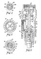
- Figure 3 is a cross-sectional view of a combination feed and dump valve for use in the system of Figure 1 or Figure 2;
- Figure 4 is a transverse cross-sectional view taken along line IV-IV of Figure 3;
- Figure 5 is a transverse cross-sectional view taken along line V-V of Figure 3;
- Figure 6 is a transverse cross-sectional view taken along line VI-Vl of Figure 3;
- Figure 7:is a view similar to Figure 3 but showing the condition of the valve at a first predetermined temperature;
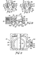
- Figure 8 is a view of the'lower section of the valve according to Figure 3 at a condition approaching a second predetermined temperature;
- Figure 9 is a view similar to Figure 8 but showing the valve at the second predetermined temperature;
- Figure 10 is a cross-sectional view of an alternative form of combination feed and dump valve; and,
- Figure 11 shows a modification to the valve according to Figure 3.
- A system according to the invention is characterised in that at a particular temperature above freezing, the panel is drained of its contents and is isolated from the storage tank so as to remain empty until the temperature of the contents of the panel rises to an appropriate level.
- It will be convenient first to describe the system utilising thermo-syphonic'circulation and an example of such a system is shown diagrammatically in Figure 1. In that arrangement, water is circulated through a panel 1 and
storage tank 2 simply through thermo-syphonic motion - i.e., based on the tenedency of warm water to rise. - A feed tube 3 connects an outlet 4 from the
storage tank 2 to an inlet 5 of the panel 1 and anexhaust tube 6 connected an outlet 7 of the panel 1 to an inlet 8 of thestorage tank 2. "Inlet" and "outlet" are so called relative to the direction of water flow under thermo-syphonic action. A coldwater supply line 9 for make-up purposes may be connected to the feed tube 3 at a location adjacent to thestorage tank 2. - In the preferred form shown, a combination drain and shut-off
valve 10 is provided in the connection between the panel inlet 5 and the storage tank outlet 4, and a further shut-off valve 11 is.provided in the connection between the panel outlet 7 and storage tank inlet 8. Bothvalves 10 and 11 are temperature responsive in that each incorporates' means, preferably in the form of an element, which responds to the temperature created by the environment to which therespective valve 10 or 11 is exposed. The temperature responsive element of thecombination valve 10 however, preferably controls both a drain port 12 and a main communication port (not shown) through which aninlet 13 and anoutlet 14 of thevalve 10 are connected. The temperature responsive element of the panel exhaust valve 11 on the other hand need only control a main communication port. - The temperature created by the environment is generally ambient temperature, but under some circumstances it may be less than ambient. For example, on a foggy night the panel 1 may be subjected to a radiation temperature which is less than ambient temperature. In a preferred form, the temperature responsive element of each of the
valves 10 and 11 is arranged to respond to the same temperature as that to which the panel is subjected and as explained above that may be either ambient temperature or a lower radiation temperature. Under some conditions of course, the ambient temperature and the radiation temperature will be the same. In the following description it will be convenient to refer to ambient temperature only and in that context the word "ambient" is to be understood as embracing "radiation" as described above. - When the system is under normal operating conditions - e.g., the ambient temperature is above 6 to 7 degrees Celsius - the main communication port of each
valve 10 and 11 remains open and the drain port 12 of thecombination valve 10 is closed. Water can then circulate between the panel 1 andstorage tank 2 in the normal manner. If the ambient temperature drops to a predetermined cut-off temperature - e.g., 6 degrees Celsius - the temperature responsive elements of thevalves 10 and 11 respond to cause the respective main communication ports to close and thereby isolate the panel 1 from thestorage tank 2. At that stage the panel 1 is full of water and no difficulty arises if the temperature does not fall significantly below 6 degrees Celsius. If the temperature does fall however and approaches freezing point, the temperature responsive element of thecombination valve 10 responds to a temperature of say 3 degress Celsius to cause the drain port 12 to open thereby allowing the panel 1 to drain its contents. Should the temperature then continue to drop towards 0 degrees Celsius there is no likelihood of the panel 1 being damaged. - When the ambient temperature increases, the reverse of the operation takes place. That is, at or about 3 degrees Celsius the drain port 12 closes and at or about 6 degrees Celsius the main communication ports open to allow the panel 1 to be filled from the
storage tank 2 and/or the coldwater supply line 9. Normal circulation then takes place. - It will be apparent that the arrangement described can be modified in many respects. For example, the valve 11 may be a pressure responsive one-way valve which opens only to allow flow from the panel 1 towards the
tank 2. Furthermore, as shown in Figure 2, the panel drainage function may be achieved through a valve 15 separate from a main shut-offvalve 21 at the panel inlet 5. In such a case the drain valve 15 is located between the shut-offvalve 21 and the panel 1. - . Figure 2 shows further possible modifications of the system according to Figure 1. In Figure 2, the panel 1 includes a
serpentine tube 16 forming the passage between the panel inlet 5 and outlet 7, whereas in the Figure 1 arrangement that passage is provided by a plurality of tubes 17 interconnectingheaders pump 20 and the positions of the inlets and outlets of the panel 1 andtank 2 have been reversed. It is to be understood however, that both the Figure 1 and Figure 2 arrangements are examples only and each is susceptible to substantial variation. - One particular form of the
combination valve 10 is shown in Figure 3 and includes ahollow body 22 having a primary chamber, which is divided into inlet andoutlet sections secondary chamber 24. Thesections orifice 25 which is subjected to control by aprimary valve member 26. Aninlet port 13 communicates with theinlet section 23a and in the Figure 1 arrangement for example, the feed line 3 connectsport 13 to the tank outlet 4. Anoutlet port 14 communicates with theoutlet section 23b and again considering the Figure 1 arrangement theport 14 is connected to the panel inlet 5. Theoutlet section 23b communicates with thesecondary chamber 24 through a transfer port 27 (see Figure 4) and that port is controlled by asecondary valve member 28. - In the valve construction according to Figure 3, the
orifice 25 and the transfer port 27 are substantially co-axial and thevalve members responsive element 29 influences operation of bothvalve members element 29 is connected to thevalve body 22 in a manner hereinafter described. - The particular
primary valve member 26 shown in Figure 3 includes astem 30 which extends axially through theorifice 25 and has oneend portion 31 attached to thesecondary valve member 28 and itsopposite end portion 32 slidably mounted in asupport spider 33. Thespider 33 is secured to thevalve body 22 against relative movement and has a number ofopenings 34 through which water passes from theinlet port 13 to the primary chamber 23 (see Figure 5). Adisc section 36 is fixed to thestem 30 at a location between its ends and carries a resilient annular sealing element 37 which is adapted to engage aseat 38 surrounding theorifice 25. Thedisc 36 is located between theinlet port 13 and thevalve seat 38 and is urged towards the orifice closing position by acompression spring 39. - The
secondary valve member 28 includes a body formed of twointerconnected parts parts co-operable screw threads 41, but other types of connections may be adopted. Acircumferential groove 42 is formed between opposed surfaces of the twoparts ring 43 which serves as a sealing element of thevalve member 28. Thepart 40a preferably has a hexagonal (or other non-circular) external shape as shown in Figure 4 so as to slidably engage within acylindrical bore 44 of asleeve 45 in such a manner that a plurality of throughpassages 46 are formed between thepart 40a and thebore 44. Such co-operation between thepart 40a andsleeve 45 provides a guide for axial movement for thevalve member 28. It is further preferred that theend portion 31 of the primary valve stem 30 is slidably located in an axial bore 37 formed in the adjacent end of thesecondary valve part 40a. - A
compression spring 48 preferably urges thesecondary valve member 28 towards a port opening position and as shown thatspring 48 may coact between thevalve body 22 and aflange 49 ofpart 40b of thesecondary valve 28. Thesleeve 45 has a frusto-conical bore 50 which merges with thecylindrical bore 44 and is located remote from the primary valve chamber 23. The '0'ring 43 is adapted to sealingly engage against the surface of both thebores drain port 51 is formed through thevalve body 22 to communicate with thesecondary chamber 24 as best shown in Figure 6. - The temperature
responsive element 29 may be secured to thevalve body 22 by means of anend cap 52 which screws into abore 53 of thebody 22. As shown, theelement 29 is preferably substantially coaxial with thevalve members part 54 which projects out of theend cap 52 for exposure to the surrounding atmosphere. Amovable stem 55 projects from the body of theelement 29 at the end thereof remote from thepart 54 and engages thesecondary valve member 28 either directly or through the intermediary of another member such as an insulatingdisc 56 as shown in Figure 3. - It is preferred substantially to insulate the
element 29 from the influence of the temperature of the contents of thechambers 23 and 24. For that purpose, thedisc 56,valve member part 40b and theend cap 52 may be made from a material such as "celcon" having low heat conduction characteristics. Those members also substantially insulate theelement 29 against heat conduction from thevalve body 22. - At least the exposed portion of the
part 54 of the temperatureresponsive element 29 is preferably coloured the same as that portion of the solar heating panel 1 through which ambient temperature influences the temperature of the panel contents. That is, the exposed outer broad surface of the panel 1 and that surface is generally coloured black in which event, thepart 54 is also preferably coloured black. The aim is to have the temperatureresponsive element 29 subjected to substantially the same solar radiation temperature as that which affects the temperature of the contents of the heating panel 1. In particular, the temperatureresponsive element 29 and the panel 1 are subjected to the same environmental conditions so that each is affected to substantially the same extent by dew point and other aspects which influence the temperature of the water in the panel 1. It may take some time for a change in the temperature of the contents of the panel 1 to be accurately reflected within thebody 22 of thevalve 10, so the arrangement described ensures that theelement 29 will respond quickly to changes which influence the internal conditions of the panel 1 so there is substantial correspondence between those conditions and the operation of theelement 29. - The
valve 10 will normally have the condition shown in Figures 3, - i.e., at ambient temperature above the first predetermined temperature which may be 6 or 7 degrees Celsius for example. In that condition, theorifice 25 is open and thetransfer port 51 is closed so water can flow between theinlet 13 and theoutlet 14, but flow to thechamber 24 is prevented. - Assuming the ambient temperature drops below say 6 degrees Celsius the
stem 55 of theelement 29 will retract into the body of theelement 29 to a distance sufficient to allow thevalve 26 to close under the influence ofspring 39, but not sufficient to allow thevalve 28 to open. That situation is shown in Figure 7 and results in thesection 23b of the primary chamber being isolated from thevalve inlet 13. Further movement of thevalve stem 30 towards the.secondary chamber 24 is prevented by engagement between thevalve seat 38 and the sealing element 37. - When the
stem 55 is restracting as described above, thevalve member 28 will follow that movement under the influence of thespring 48. Thevalve member 26 in turn follows the movement of thevalve member 28 because of the influence ofspring 39. All threecomponents ring 43 emerges from thecylindrical bore 44 and enters into the small diameter end of the frusto-conical bore 50. At the position shown in Figure 7 the '0'ring 43 nevertheless continues to maintain a fluid tight seal with the surface ofbore 50. - If the ambient temperature then drops below the second predetermined temperature, which may be 3 or 4 degrees Celsius for example, the
stem 55 will retract further into the body of theelement 29 and thevalve member 28 follows that movement under the influence of thespring 48. The primary valve stem 30 however, is held against movement with thevalve member 28 as mentioned above so that thesecondary valve part 40a slides along thestem end 31 towards the position shown in Figure'8. As a result of the foregoing, the '0'ring 43 is moved further towards the large diameter end of thebore 50 and its sealing influence is progressively diminished. The pressure differential existing between theprimary chamber section 23b (high pressure) and the secondary chamber 24 (low pressure) causes the '0'ring 43 to be compressed in the axial direction of thevalve member 28 thereby maintaining the sealing contact between the '0'ring 43 and the surface of thebore 50. A position is reached however, at which the pressure within thechamber section 23b overcomes the sealing influence of the '0'ring 43 and a gap 57 appears between the '0'ring 43 and the surface of thebore 50 as shown in Figure 9. That gap 57 is created relatively quickly immediately the seal is breached because the resulting reduction in pressure differential on opposite sides of the '0'ring 43 causes the '0'ring 43 to return suddenly to its uncompressed state. Water is then able to pass from theprimary chamber section 23b into thesecondary chamber 24 and then out through thedrain port 51. Assuming thevalve 10 is connected into a system as shown in Figure 1, that operation can result in the panel 1 being drained of its contents. In that regard, the valve 11 would have closed at substantially the same time as theorifice 25 of thevalve 10 was closed. - When the ambient temperature starts to rise, the
element 29 will respond by moving thestem 55 outwardly towards the transfer port 27. Thesecondary valve member 28 is thereby moved against the influence of thespring 48 and progressively moves towards a position at which the '0'ring 43 sealingly engages the surface of thebore 50. In due course, assuming a continuing increase in temperature, thesecondary valve part 40a will engage theshoulder 58 on theprimary valve stem 30 and theprimary valve member 26 will be thereafter moved to open theorifice 25. The '0'ring 43 will of course be moved beyond the frusto-conical bore 50 into thecylindrical bore 44. - The temperature responsive element may be of a conventional kind having within it a material which expands and contracts in response to variations in temperature. The
stem 55 of theelement 29 is arranged to move with that expansion and contraction. - The desired sudden opening of the transfer port 27 can be achieved in several ways.. In the construction shown, it is achieved in part by the taper of the frusto-
conical bore 50 and the relatively large cross-sectional size of the '0'ring 43. By way of example, the included angle of thebore 50 may be 30°, or thereabouts, , and the inner diameter of the '0'ring 43 may be in the range of 50 to 60% of the outer diameter (preferably approximately 55%). - It is possible to achieve the desired shut-off and drainage facility in valve constructions different to that shown in Figures 3 to 9. One possible variation is shown in Figure 10 and components of that construction which correspond to components of the Figure 3 construction have been given like reference numerals but in the series 100 - 199.
- In the Figure 10 construction, the temperature responsive element 129 acts between the
valve member 128 and a cushioning or biasingspring 148 which bears against part of thevalve body 122. Thecushioning spring 148 is designed to impose a lower force on the temperature responsive element 129 than does the biasing spring 139 of thevalve member 128. In this construction there is no equivalent to the secondary chamber of the construction according to Figure 3 and thesecondary valve 128 is of relatively simple construction. - In the cold unexpanded condition of the temperature responsive element 129, the
valve member 126 is closed against thevalve seat 138 surrounding theorifice 125 and thecushioning spring 148 holds the temperature responsive element 129 andvalve member 128 well clear of theseat 159 surrounding theport 151 as shown in Figure 10. As the temperature increases and the element 129 expands thecushioning spring 148 is compressed but thevalve member 126 initially remains closed under the action of its biasing spring 139. At a temperature of say 3 degrees Celsius, or thereabouts, thevalve member 128 engages thevalve seat 159 so as to close theport 151 and subsequent expansion of the element 129 acts against the valve member 216. When the temperature reaches say 6 degrees Celsius,or thereabouts, the expansion force is sufficient to move thevalve member 126 so that theorifice 125 is opened against the action of the biasing spring 139. The reverse operation of course occurs as the temperature falls. - The valve 11 which is used at the panel inlet may be substantially the same as either of the two combination valves described above. Alternatively, the valve 11 may be substantially as described except for omission of the drain port or, in the Figure 3 type arrangement, closure of the transfer port under all conditions.
- In the preferred arrangement, the valve 11 is substantially as described in relation to Figures 1 to 9 except that a vacuum break facility is added and such a modification is shown in Figure 11. Components of that construction which correspond to components of the Figures 1 to 9 construction will be given like reference numerals except that they will be in the series 200-299.
- The Figure 11 construction includes an
air valve 260 which is operable to connect thechamber section 23b with atmosphere. Thevalve 260 can be of any appropriate construction, but in the arrangement shown it includes acylindrical housing 261 having anopening 262 formed through anend wall 263 and having its opposite end communicating with thechamber section 23b. Apiston 264 is loosely mounted within thehousing 261 and engages an '0'ring 265 to prevent passage of air or other fluid through theopening 262. - If the
valve 211 is included in the Figure 1 system theair valve 260 will avoid the formation of a vacuum within the panel 1. Such a vacuum can be created during draining of the panel 1 as a consequence to opening of the draining port 12, and under those circumstances the resulting pressure differential across thepiston 264 will cause thevalve 260 to open so that the interior of the panel is subjected to atmospheric pressure. Thevalve 260 will close as the panel 1 is being refiled because of the high pressure then existing within the panel. - The
air valve 260, or a similar valve can be incorporated in any form of valve 11 as might be used in systems of the kind described in relation to Figures 1 and 2. Alternatively, such an air valve may be located separate from the exhaust valve 11 so as to be located within the panel 1 or between the panel 1 and the exhaust valve 11. - It will be apparent from the foregoing that the present invention provides an improved solar heating system in that the panel is effectively protected against the consequences of low temperature conditions. Furthermore, the basic temperature responsive valve of the present invention has the substantial advantage of responding to changes in the environmental conditions rather than the less accurate changes in the internal conditions of the valve itself. The combination valve of the invention provides a relatively simple and effective means of achieving control over both main flow and drainage facilities.
Claims (21)
Priority Applications (1)
| Application Number | Priority Date | Filing Date | Title |
|---|---|---|---|
| AT81303936T ATE9402T1 (en) | 1980-08-28 | 1981-08-27 | SOLAR HEATING SYSTEM AND VALVE. |
Applications Claiming Priority (2)
| Application Number | Priority Date | Filing Date | Title |
|---|---|---|---|
| AU5309/80 | 1980-08-28 | ||
| AUPE530980 | 1980-08-28 |
Publications (2)
| Publication Number | Publication Date |
|---|---|
| EP0047144A1 true EP0047144A1 (en) | 1982-03-10 |
| EP0047144B1 EP0047144B1 (en) | 1984-09-12 |
Family
ID=3768662
Family Applications (1)
| Application Number | Title | Priority Date | Filing Date |
|---|---|---|---|
| EP81303936A Expired EP0047144B1 (en) | 1980-08-28 | 1981-08-27 | Solar heating system and valve |
Country Status (10)
| Country | Link |
|---|---|
| US (1) | US4454890A (en) |
| EP (1) | EP0047144B1 (en) |
| JP (1) | JPS5773355A (en) |
| AT (1) | ATE9402T1 (en) |
| AU (1) | AU545672B2 (en) |
| DE (1) | DE3166039D1 (en) |
| ES (1) | ES8302888A1 (en) |
| IL (1) | IL63674A (en) |
| NZ (1) | NZ198183A (en) |
| ZA (1) | ZA815692B (en) |
Cited By (5)
| Publication number | Priority date | Publication date | Assignee | Title |
|---|---|---|---|---|
| FR2562982A1 (en) * | 1984-04-12 | 1985-10-18 | Raffinage Cie Francaise | Heating installation equipped with an automatic draining device intended to avoid freezing effects |
| EP2149758A1 (en) | 2008-07-30 | 2010-02-03 | Novotherm | Method for avoiding freezing in a heating system and associated heating installation |
| AU2005220171B2 (en) * | 2004-10-13 | 2010-12-16 | Cap-Aus Pty Limited | Freeze Protection Apparatus for Solar Hot Water System |
| CN102141168A (en) * | 2010-01-29 | 2011-08-03 | 张润忠 | Pressure-control valve and solar water heater |
| CN105737415A (en) * | 2016-04-21 | 2016-07-06 | 伯恩太阳能科技有限公司 | Liquid replenishing tank of solar system |
Families Citing this family (11)
| Publication number | Priority date | Publication date | Assignee | Title |
|---|---|---|---|---|
| US4638828A (en) * | 1985-10-22 | 1987-01-27 | Barrineau Sr Wyman L | Water temperature actuated drip valve |
| US5388287A (en) * | 1993-07-12 | 1995-02-14 | Ecowater Systems, Inc. | Countertop faucet assembly |
| ES2101625B1 (en) * | 1994-04-07 | 1997-12-16 | Rayosol S A | ANTIFREEZE SYSTEM FOR SOLAR ENERGY COLLECTION EQUIPMENT. |
| US6530391B1 (en) * | 2001-08-31 | 2003-03-11 | Research By Copperhead Hill, Inc. | Temperature activated valve |
| DE20219008U1 (en) * | 2002-12-06 | 2004-04-22 | Interforge Klee Gmbh | Water fitting has pin for valve plate protruding centrally from pressure side valve face and which together with support disc installed on pressure side of shut-off valve forms guide for valve plate |
| DE202005008464U1 (en) * | 2005-05-27 | 2006-11-16 | Interforge Klee Gmbh | Frost proof valve device for public water supply network, has driving unit with bypass line that connects vertical and horizontal sections of connecting channel which join inflow and discharge openings |
| ATE424486T1 (en) * | 2005-05-27 | 2009-03-15 | Interforge Klee Gmbh | FROST-PROOF EXTERNAL WALL VALVE |
| ITMI20071465A1 (en) * | 2007-07-20 | 2009-01-21 | Edn S R L | SOLAR PANEL FOR WATER HEATING |
| EP2195585A1 (en) * | 2007-10-03 | 2010-06-16 | Dux Manufacturing Limited | A solar hot water system and method of operating a solar hot water system |
| US20110163534A1 (en) * | 2010-01-07 | 2011-07-07 | Vincent Peter Biel | Solar hot water storage system and dual passageway fitting assembly |
| CN102182831B (en) * | 2011-04-22 | 2015-03-18 | 张双桥 | Screw type hollow frost valve |
Citations (6)
| Publication number | Priority date | Publication date | Assignee | Title |
|---|---|---|---|---|
| US1630907A (en) * | 1924-06-04 | 1927-05-31 | Royer Georges Gaston | Automatic means for running off liquid from containers at predetermined conditions of temperature |
| US3364948A (en) * | 1964-05-09 | 1968-01-23 | Seiffert Gunther | Alternately seating temperature valve |
| FR1578680A (en) * | 1967-10-12 | 1969-08-14 | ||
| US4191166A (en) * | 1977-12-27 | 1980-03-04 | Richdel, Inc. | Solar heat system |
| FR2441689A1 (en) * | 1978-11-13 | 1980-06-13 | Duval Eugene | APPARATUS FOR PROTECTING SOLAR ENERGY COLLECTORS FROM FREEZING |
| EP0025150A1 (en) * | 1979-09-10 | 1981-03-18 | Microphor, Inc. | Temperature controlled valve mechanism and method |
Family Cites Families (3)
| Publication number | Priority date | Publication date | Assignee | Title |
|---|---|---|---|---|
| US2716418A (en) * | 1950-12-29 | 1955-08-30 | Int Harvester Co | Thermostatic drain valve |
| US3853269A (en) * | 1973-11-08 | 1974-12-10 | Kysor Industrial Corp | Temperature actuated valve |
| US4216902A (en) * | 1978-03-23 | 1980-08-12 | Braukmann Armaturen Ag | Thermostatic control valve |
-
1981
- 1981-08-18 ZA ZA815692A patent/ZA815692B/en unknown
- 1981-08-19 AU AU74447/81A patent/AU545672B2/en not_active Ceased
- 1981-08-25 US US06/296,174 patent/US4454890A/en not_active Expired - Fee Related
- 1981-08-27 NZ NZ198183A patent/NZ198183A/en unknown
- 1981-08-27 AT AT81303936T patent/ATE9402T1/en not_active IP Right Cessation
- 1981-08-27 DE DE8181303936T patent/DE3166039D1/en not_active Expired
- 1981-08-27 ES ES81505475A patent/ES8302888A1/en not_active Expired
- 1981-08-27 EP EP81303936A patent/EP0047144B1/en not_active Expired
- 1981-08-27 IL IL63674A patent/IL63674A/en unknown
- 1981-08-28 JP JP56134344A patent/JPS5773355A/en active Pending
Patent Citations (7)
| Publication number | Priority date | Publication date | Assignee | Title |
|---|---|---|---|---|
| US1630907A (en) * | 1924-06-04 | 1927-05-31 | Royer Georges Gaston | Automatic means for running off liquid from containers at predetermined conditions of temperature |
| US3364948A (en) * | 1964-05-09 | 1968-01-23 | Seiffert Gunther | Alternately seating temperature valve |
| FR1578680A (en) * | 1967-10-12 | 1969-08-14 | ||
| US4191166A (en) * | 1977-12-27 | 1980-03-04 | Richdel, Inc. | Solar heat system |
| FR2441689A1 (en) * | 1978-11-13 | 1980-06-13 | Duval Eugene | APPARATUS FOR PROTECTING SOLAR ENERGY COLLECTORS FROM FREEZING |
| US4280478A (en) * | 1978-11-13 | 1981-07-28 | Duval Eugene F | Freeze protection apparatus for solar collectors |
| EP0025150A1 (en) * | 1979-09-10 | 1981-03-18 | Microphor, Inc. | Temperature controlled valve mechanism and method |
Cited By (7)
| Publication number | Priority date | Publication date | Assignee | Title |
|---|---|---|---|---|
| FR2562982A1 (en) * | 1984-04-12 | 1985-10-18 | Raffinage Cie Francaise | Heating installation equipped with an automatic draining device intended to avoid freezing effects |
| AU2005220171B2 (en) * | 2004-10-13 | 2010-12-16 | Cap-Aus Pty Limited | Freeze Protection Apparatus for Solar Hot Water System |
| EP2149758A1 (en) | 2008-07-30 | 2010-02-03 | Novotherm | Method for avoiding freezing in a heating system and associated heating installation |
| FR2934672A1 (en) * | 2008-07-30 | 2010-02-05 | Novotherm | METHOD FOR FREEZING A HEAT GENERATION SYSTEM AND ASSOCIATED HEAT PRODUCTION PLANT |
| CN102141168A (en) * | 2010-01-29 | 2011-08-03 | 张润忠 | Pressure-control valve and solar water heater |
| CN102141168B (en) * | 2010-01-29 | 2014-05-07 | 张润忠 | Pressure-control valve and solar water heater |
| CN105737415A (en) * | 2016-04-21 | 2016-07-06 | 伯恩太阳能科技有限公司 | Liquid replenishing tank of solar system |
Also Published As
| Publication number | Publication date |
|---|---|
| US4454890A (en) | 1984-06-19 |
| AU7444781A (en) | 1982-03-04 |
| IL63674A0 (en) | 1981-11-30 |
| ES505475A0 (en) | 1983-02-01 |
| EP0047144B1 (en) | 1984-09-12 |
| IL63674A (en) | 1985-10-31 |
| DE3166039D1 (en) | 1984-10-18 |
| ZA815692B (en) | 1982-08-25 |
| ATE9402T1 (en) | 1984-09-15 |
| ES8302888A1 (en) | 1983-02-01 |
| AU545672B2 (en) | 1985-07-25 |
| JPS5773355A (en) | 1982-05-08 |
| NZ198183A (en) | 1984-08-24 |
Similar Documents
| Publication | Publication Date | Title |
|---|---|---|
| EP0047144A1 (en) | Solar heating system and valve | |
| US4848389A (en) | Freeze protection device | |
| US3380464A (en) | Thermostatic freezing valve | |
| US4450868A (en) | Freeze protection apparatus for solar collectors | |
| CN101725717B (en) | Antifreezing valve device for hydraulic and/or water storage systems | |
| US4815491A (en) | Freeze protection device | |
| US4460007A (en) | Valve mechanism | |
| US4280478A (en) | Freeze protection apparatus for solar collectors | |
| GB2107829A (en) | Thermostatic valves, and solar water heating systems incorporating the same | |
| US4356833A (en) | Temperature controlled valve mechanism and method | |
| US4016901A (en) | Thermostatic valve | |
| US4681088A (en) | Freeze protection valve for solar heaters | |
| US4205698A (en) | Detachable water pipe freeze preventing device | |
| US4557252A (en) | Freeze protection valve and system | |
| CA1116145A (en) | Thermostatic self-powered drain valve | |
| CA1193583A (en) | Temperature controlled valve | |
| EP0059599B1 (en) | Valve mechanism for low temperature applications | |
| US4307707A (en) | Control valve for solar heating systems | |
| US4360036A (en) | Thermostatic self-powered drain valve | |
| US6920844B1 (en) | Thermal expansion arrester for water heaters | |
| US5169291A (en) | Water heater with shut-off valve | |
| US3320965A (en) | Freeze protection dump valve | |
| US5113891A (en) | Water freeze guard valve | |
| CA1188172A (en) | Solar heater system and valve | |
| GB2112907A (en) | Valve and system incorporating same |
Legal Events
| Date | Code | Title | Description |
|---|---|---|---|
| PUAI | Public reference made under article 153(3) epc to a published international application that has entered the european phase |
Free format text: ORIGINAL CODE: 0009012 |
|
| AK | Designated contracting states |
Designated state(s): AT BE CH DE FR GB IT LU NL SE |
|
| 17P | Request for examination filed |
Effective date: 19820910 |
|
| ITF | It: translation for a ep patent filed | ||
| GRAA | (expected) grant |
Free format text: ORIGINAL CODE: 0009210 |
|
| AK | Designated contracting states |
Designated state(s): AT BE CH DE FR GB IT LI LU NL SE |
|
| PG25 | Lapsed in a contracting state [announced via postgrant information from national office to epo] |
Ref country code: SE Effective date: 19840912 Ref country code: NL Effective date: 19840912 Ref country code: AT Effective date: 19840912 |
|
| REF | Corresponds to: |
Ref document number: 9402 Country of ref document: AT Date of ref document: 19840915 Kind code of ref document: T |
|
| REF | Corresponds to: |
Ref document number: 3166039 Country of ref document: DE Date of ref document: 19841018 |
|
| ET | Fr: translation filed | ||
| NLV1 | Nl: lapsed or annulled due to failure to fulfill the requirements of art. 29p and 29m of the patents act | ||
| PLBE | No opposition filed within time limit |
Free format text: ORIGINAL CODE: 0009261 |
|
| STAA | Information on the status of an ep patent application or granted ep patent |
Free format text: STATUS: NO OPPOSITION FILED WITHIN TIME LIMIT |
|
| PG25 | Lapsed in a contracting state [announced via postgrant information from national office to epo] |
Ref country code: LU Free format text: LAPSE BECAUSE OF NON-PAYMENT OF DUE FEES Effective date: 19850831 |
|
| 26N | No opposition filed | ||
| PG25 | Lapsed in a contracting state [announced via postgrant information from national office to epo] |
Ref country code: LI Effective date: 19870831 Ref country code: CH Effective date: 19870831 |
|
| BERE | Be: lapsed |
Owner name: ACTROL INDUSTRIES PTY. LTD Effective date: 19870831 |
|
| REG | Reference to a national code |
Ref country code: CH Ref legal event code: PL |
|
| PG25 | Lapsed in a contracting state [announced via postgrant information from national office to epo] |
Ref country code: GB Free format text: LAPSE BECAUSE OF NON-PAYMENT OF DUE FEES Effective date: 19880827 |
|
| PG25 | Lapsed in a contracting state [announced via postgrant information from national office to epo] |
Ref country code: FR Free format text: LAPSE BECAUSE OF NON-PAYMENT OF DUE FEES Effective date: 19890428 |
|
| PG25 | Lapsed in a contracting state [announced via postgrant information from national office to epo] |
Ref country code: DE Effective date: 19890503 |
|
| GBPC | Gb: european patent ceased through non-payment of renewal fee | ||
| REG | Reference to a national code |
Ref country code: FR Ref legal event code: ST |
|
| PG25 | Lapsed in a contracting state [announced via postgrant information from national office to epo] |
Ref country code: BE Effective date: 19890831 |