EP0047606B1 - Dispositif d'entrée dans un système de traitement de données - Google Patents
Dispositif d'entrée dans un système de traitement de données Download PDFInfo
- Publication number
- EP0047606B1 EP0047606B1 EP81303862A EP81303862A EP0047606B1 EP 0047606 B1 EP0047606 B1 EP 0047606B1 EP 81303862 A EP81303862 A EP 81303862A EP 81303862 A EP81303862 A EP 81303862A EP 0047606 B1 EP0047606 B1 EP 0047606B1
- Authority
- EP
- European Patent Office
- Prior art keywords
- page
- rotatable shaft
- page sheet
- sheet unit
- shaft
- Prior art date
- Legal status (The legal status is an assumption and is not a legal conclusion. Google has not performed a legal analysis and makes no representation as to the accuracy of the status listed.)
- Expired
Links
Images


Classifications
-
- B—PERFORMING OPERATIONS; TRANSPORTING
- B42—BOOKBINDING; ALBUMS; FILES; SPECIAL PRINTED MATTER
- B42F—SHEETS TEMPORARILY ATTACHED TOGETHER; FILING APPLIANCES; FILE CARDS; INDEXING
- B42F13/00—Filing appliances with means for engaging perforations or slots
- B42F13/30—Filing appliances with means for engaging perforations or slots having a set of rods within a set of tubes for a substantial distance when closed
- B42F13/32—Filing appliances with means for engaging perforations or slots having a set of rods within a set of tubes for a substantial distance when closed the nesting portions of the rods and tubes being straight
- B42F13/34—Filing appliances with means for engaging perforations or slots having a set of rods within a set of tubes for a substantial distance when closed the nesting portions of the rods and tubes being straight with the rods locking in the tubes
-
- G—PHYSICS
- G06—COMPUTING OR CALCULATING; COUNTING
- G06F—ELECTRIC DIGITAL DATA PROCESSING
- G06F3/00—Input arrangements for transferring data to be processed into a form capable of being handled by the computer; Output arrangements for transferring data from processing unit to output unit, e.g. interface arrangements
- G06F3/01—Input arrangements or combined input and output arrangements for interaction between user and computer
- G06F3/02—Input arrangements using manually operated switches, e.g. using keyboards or dials
- G06F3/023—Arrangements for converting discrete items of information into a coded form, e.g. arrangements for interpreting keyboard generated codes as alphanumeric codes, operand codes or instruction codes
- G06F3/0238—Programmable keyboards
Definitions
- This invention relates to an input device for use in inputting multiple items of information into an information processing system by keying operations, more particularly, the present invention relates to a roll type input device in which a plurality of page sheets bearing input information designations are provided in the form of a roll and a desired page sheet is selected by rotating the roll of page sheets.
- An input device of this type an item input device, usually employs a structure in which a page drum is formed by fixing respective first ends of each of a plurality of plastic page sheets directly to the circumferential surface of a rotating shaft, and this page drum is accommodated in a main device body in such a way as to be withdrawable from the device body, and insertable into the device body, to provide for exchange of page drums.
- the rotating shaft When an operator operates a desired page selection key of a keyboard of the device, the rotating shaft automatically rotates through a specified angle, in a direction opposite to those in which page sheets are rolled or wound on the shaft, thereby to bring about a setting condition in which a second end of a desired page sheet (opposite to the first end of that sheet) is placed at a page sheet guide exit of the device. Thereafter, the rotating shaft automatically rotates in a direction the same as that in which the page sheets are rolled or wound on the shaft, to guide the desired page sheet to a position below input keys of the keyboard of the device.
- the input keys of the keyboard are provided with functional displays (each key is provided with a designation of its function) in accordance with designation information carried by the desired page sheet.
- a key signal generated by the input key, and a page sheet identification signal, which depends on the page selection key previously actuated by the operator, and a page drum identification signal, which identifies with the particular kind of page drum inserted into the device, are input into the data processing system as input information.
- a page drum is built into the main body of the item input device as explained above, in such a way as to be exchangeable for another page drum.
- page drum replacement has been very troublesome because such replacement has been effected manually by opening the keyboard and a cover of the main body of the item input device.
- existing page drums have a cartridge type structure in which four rotating shafts are provided around which extends an endless belt for holding the page sheets in the winding direction, with an accommodation cabinet therefore, in addition to the rotating shafts and page sheets. This makes replacement troublesome because of the heavy weight and large size of the replaceable units. In addition, storage of cartridges required wider space.
- An existing item input device employs, moreover, a structure in which page selection is carried out by rotating the rotating shaft on which page sheets are wound in the direction in which the page sheets are wound, and in the reverse direction, in such a way that this can result in slackness in the page sheets, other than the page sheet selected at the time of page selection.
- page selection operations are repeated several times, the end locations of page sheets during winding can become irregular and mis-selection may occur and such mis-selection can become a significant problem as page selection operation speed increases.
- JP-A-54 133 832 discloses an input device having a page drum in which first ends of each of a plurality of flexible page sheets are directly connected to the circumferential surface of a rotatable shaft of the device, with those ends spaced apart around the circumference of the shaft. Exchange of the page drum thus involves exchange of the rotatable shaft.
- GB-A-1 092 386 discloses an input device having an operational disposition in which a plurality of flexible page sheets, bound together in a page sheet unit separate from a rotatable shaft of the device, are wound around the circumference of the rotatable shaft in such a manner that the sheets overlap one another around the circumference with their radially outermost ends spaced apart around the circumference, the device being operable to select a desired page sheet by rotation of the rotatable shaft in in the direction of winding of the page sheets in the said operational disposition, and to deploy a selected page sheet, to a display location, by rotation of the shaft in the opposite direction.
- an input device for a data processing system, having an operational disposition in which-a plurality of flexible page sheets, bearing input information designations, bound together in a page sheet unit separate from a rotatable shaft of the device, are wound around the circumference of the rotatable shaft in such a manner that the sheets overlap one another around the circumference with their radially outermost ends spaced apart around the circumference, the device being operable to select a desired page sheet by rotation of the rotatable shaft in the direcion of winding of the page sheets in the said operational disposition, and to deploy a selected page sheet, to a display location, by rotation of the shaft in the opposite direction, characterised in that the ends of the page sheets of the page sheet unit which are radially innermost in the said operational disposition are fixed to a surface of a flexible base sheet of the page sheet unit and are bound in the page sheet unit so as to be spaced apart around the said circumference, in the said operational disposition, the flexible base sheet having at one end a linkage pin opposite ends
- An embodiment of the present invention can provide an item input device in which the disadvantages of previous proposals are, in substance, overcome, and in which page exchange can be effected simply.
- An embodiment of the present invention can provide an item input device which can ensure stable and reliable page selection operation, and in which mis-selection does not occur even for high speed operation.
- an embodiment of the present invention can provide an item input device wherein page sheets are wound by the rotating shaft, during page winding, through rotation of the rotating shaft in the winding direction, whilst, during page selection, a rotating force is transmitted to the rotating shaft through the wound page sheets such that the rotating shaft rotates in a reverse direction.
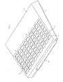
- FIG 2 is a sectional view illustrating the interior of the device shown in Figure 1.
- a pair of side walls 6, arranged face-to-face with one another, are provided on the upper surface (as seen in Figure 2) of base plate 1 (in Figure 2, only one side wall 6 is indicated), a keyboard 7 mounting push button switches 5 is provided between the side walls 6, and a page selection mechanism 9 is provided to the rear (to the right in Figure 2) of the keyboard 7.
- the keyboard 7 is provided with a PC board 72 on which are mounted switching parts 51 of the push button switches 5, and a PC board 73 on which are mounted circuit elements such as a keyboard encoder etc.
- the PC boards 72 and 73 are spaced by U-shaped metal pieces 71 provided at opposite ends of the PC boards.
- a switch guide plate 74 for guiding keytops 52 of the switches 51, is provided, whilst below PC board 73 a page sheet guide plate 75 is provided for guiding a page sheet unit 14, as explained in more detail below.
- the page selection mechanism 9 has a rotating shaft 91 for winding a page sheet unit 14, a drive shaft 92 connected to a stepping motor (not illustrated in Figure 2) for rotating the rotating shaft 91, an endless belt 93 which functions as a clamping member for holding a page sheet unit 14 in a winding direction of the rotating shaft 91, and shafts 94, 95 and 96 for bridging the belt 93 between and around the shafts 91 and 92.
- the shaft 96 is freely rotatable with respect to a shaft 97, in order to maintain constant tension in the belt 93.
- An inclined guide plate 10 is provided, in parallel to the guide plate 75, on the base plate 1 below the keyboard 7, whilst guide plates 11 and 12, forming a guide path for a selected page sheet, are provided in a space extending from the rotating shaft 91 to the guide plate 74.
- the space between the guide plates 10 and 75 forms a page sheet unit guide path 13, with a forward end (to the left in Figure 2) which opens onto the exchange mouth 4, while a rearward end thereof opens onto the rotating shaft 91.
- Figure 2 illustrates the condition of the device when a page sheet unit 14 is being guided along the path 13 from the exchange mouth 4.
- Figure 3 is a perspective view illustrating one example of a page sheet unit 14 as employed in an embodiment of the present invention.
- the page sheet 14 comprises a plurality of page sheets 140, each of the same shape, consisting of a flexible material such as polyester film, and a base sheet 141 consisting of a non-transparent flexible material.
- Each page sheet 140 carries information designations (symbols, signs, characters etc - not illustrated) provided thereon by printing for example, which information gives an indication of the functions of pushbutton switches 5 of the input key group B of the keyboard 7 when that page sheet is selected and in place so that the designations thereon are associated with push button switches 5 in through holes 2.
- Respective page sheets 140 carry designations of different kinds of input data, so that the switches can be shown each to correspond to a plurality of items of data, depending upon which page sheet 140 is selected and in place.
- the base sheet 141 is a little thicker than the page sheets 140 and a take-up end thereof is provided with a linkage pin 142 of metal.
- page sheet unit identification holes 143 and page sheet identification holes 144 and 145 which are seen arrayed in lines in Figure 3, and through which light can pass, are provided, and thereby page identification means is formed on the page sheet unit 14.
- One end of each page sheet 140 is fixed to the base sheet 141 with a constant spacing between those ends, as shown in Figure 4.
- Figure 5 illustrates a page sheet unit 14 when the base sheet 141 is wound up in the fashion of a drum.
- the ends of the page sheets 140 opposite to the ends fixed to the base sheet, are exposed around the periphery of the drum as shown in Figure 5.
- a predetermined length of each page sheet 140 is exposed.
- the length of page sheet exposed is a for each page sheet except a final page sheet 140".
- the final or last page sheet 140 part of which is covered by a starting or first page sheet 140', when the page sheet unit is wound as shown in Figure 5, has an exposed length b.
- Figure 6 is a plan view, to an enlarged scale, of the page sheet identification means provided at one side of the base sheet 141 of Figure 3.
- a first column of holes 144 for page sheet identification, comprises a number of holes equal to the number of page sheets 140 of the page sheet unit 14, aligned along the direction in which page sheets 140 are spaced along the base sheet 141.
- a second column of holes 145 for page sheet identification is formed with the holes at centres each between a pair of holes of the firsrt column 144.
- the holes of the second column are of the same shape and the same slit width as those of the first column except for the first hole 145a of the second column 145, located at a starting end of base sheet 141, which is formed at a position along the same line as a first hole 144a of the first column 144, but with a wider slit width.
- each hole 143 at a position aligned with one of the holes of the first column 144 but with a slit width wider than that of the first hole 145a of the second column 145.
- a plurality of page sheets 140 bearing different data items are prepared in advance and the number of page sheet identification holes 143 and locations thereof are different for each page sheet unit.
- FIG. 7 schematically illustrates conditions when the base sheet 141 is wound on the rotating shaft 91.
- a light emitting element 152 consisting of a light emitting diode (LED)
- a light sensing element 154 consisting of a phototransistor
- 152a and 154a are, respectively, a light emitting element and a light sensing element for detecting the holes of the first column 144 for page sheet identification
- 152b and 154b are, respectively, a light emitting element and a light sensing element for detecting the holes of the second column 145 for page sheet identification
- 152c and 154c are, respectively, a light emitting element and a light sensing element for detecting the holes of the page sheet identification column 143 for page sheet unit identification.
- 156a, 156b, 156c and 156d are invertor circuits
- 157 is a AND circuit
- 158 is a D-type flip-flop circuit, of which a terminal D is held at a constant voltage H, for holding a page pulse generated in response to detection of a first column hole 144
- 159 is a counter-circuit for counting output pulses of flip-flop 158, which is clocked by clock pulses of a constant period
- 160 is a D-type flip-flop circuit for holding a page unit pulse generated in response to detection of a page unit identification column hole 143
- 161 is a counter circuit which counts output signals of flip-flop 160, which is clocked by clock pulses of a constant period.
- pulse waveform A indicates an output waveform of invertor 156a
- B indicates an output waveform of invertor 156b
- C indicates an output waveform of flip-flop circuit 158
- D indicates an output waveform of AND circuit 157
- E indicates an output waveform of invertor 156c
- F indicates an output waveform of flip-flop circuit 160.
- the light sensing elements 154a, 154b, 154c operate when light emitted from a light emitting element 152a, 152b, 152c passes through a hole (a first column hole 144, a second column hole 145, and an identification hole 143, respectively) and transmit a slit pulse of width corresponding to the slit width of the detected hole to inverters 156a, 156b, 156c respectively.
- page pulses as shown in waveform A (which are generated upon detection of holes of column 144 which correspond to page sheets 140) are sequentially input to input terminal T of flip-flop 158 the output terminal Q of the flip-flop 158 is set.
- Clear pulses (a pulse train inverted with respect to the pulse train of B by inverter 156d) which are sequentially input to a clear terminal R of flip-flop 158 from the inverter 156b clear the output Q after each pulse of waveform A, and thereby output pulses of flip-flop 158 as shown in waveform C are sequentially input to the counter circuit 159 and counted.
- the flip-flop 158 has a structure such that it is set by each page pulse of waveform A and then sequentially cleared by each clear pulse corresponding to an inverted pulse of waveform B. This ensures that extra or spurious pulses are not counted even when page pulses of high frequency are generated (as illustrated at G in waveform A) during page selection, as a result of unwanted external vibration, for example.
- the light sensing elements 154a, 154b operate simultaneously to cause generation of pulses H and as shown in waveforms A and B. These pulses cause a pulse as shown in waveform D to be input to the counters 159,161 from the AND circuit 157. This is a reset pulse which resets the count values of counters 159, 161, at a constant period and initialises the counters.
- Identification signals provided by this identification circuit are generated as follows.
- the counters 159, 161 are initialised by the first reset pulse shown in waveform D, due to the simultaneous provision of pulses H and I of waveforms A and B.
- the rotating shaft 91 is so controlled as to make several turns (two turns in one example of an embodiment of this invention) during the period over which a page sheet unit 14 is wound onto shaft 91 and a desired page sheet is set.
- the counter 161 sequentially counts the output pulses (see waveform F) of the flip-flop 160, which are generated in dependence upon signals indicating the existence or non- existence of page unit identification holes 143 (see waveform E) obtained in synchronisation with page pulses of waveform A (and hence of waveform C) and the counter 161 outputs a count value reached when a second reset pulse is applied, to an external data processing system, as a page sheet unit identification signal.
- This identification signal is output for each rotation of the page sheet unit 14.
- the counter 159 which is initialised by the first reset pulse, sequentially counts output pulses (waveform C) of the flip-flop 158 until the second reset pulse is applied, and outputs the count value to the data processing system as data indicating that a take-up condition of the page sheet unit 14 has been achieved (a condition in which page sheet unit 14 has been completely taken onto the rotating shaft 91).
- the counter 159 which is initialised again by the second reset pulse, sequentially counts the output pulses a flip-flop 158 until a third reset pulse is applied, and inputs this counted value to the data processing system as a selected page sheet identification signal.
- the counter 159 counts the output pulses of the flip-flop 158 until the rotating shaft 91 makes a turn in the reverse direction, which turn is for guiding the selected page sheet to a position above the keyboard 7, and this counted value is input to the data processing system as data indicating the achievement of a page sheet display condition.
- the counter 159 sends a page sheet unit take-up condition signal, a selected page sheet identification signal, and a selected page sheet display condition signal.
- the data processing system can identify what kind of page sheet unit has been loaded, and which page sheet has been selected, from the selected page sheet identification signal and the page sheet unit identification signal obtained from counter 161, and thereby a code signal generated by depression of a push button switch 5 can be defined so as to correspond correctly to the designation of the function of the push button switch 5 given by the selected page sheet.
- FIG. 10 is a perspective view of the page selection mechanism 9 of an embodiment of the present invention.
- 91 is a rotating shaft
- 92 is a drive shaft
- 93 is an endless belt
- 94 to 97 are shafts
- 10, 11 and 12 are guide plates.
- 98 and 99 are one-way clutches, which each rotate in synchronisation or in mesh with shaft 92 for only one direction of rotation of the drive shaft 92 but which rotate freely (free wheel) for the other direction of rotation of the shaft 92.
- Clutch 98 is provided at an intermediate position along shaft 92 and clutch 99 is provided at one end of the drive shaft 92.
- 100 is a stepping motor, comprising a pulse motor
- 101 is a seesaw switch from turning the motor ON and OFF.
- 102,103,104 and 105 are gears
- 106,107,108 and 109 are pulleys
- 110 is a recovery coil spring
- 111, 112 and 113 are metal holding plates
- 114 is a metal bottom plate
- 115, 116 and 117 are rollers
- 118 is a support plate, mounted on the holding plate 111, which supports three light sensing elements 154 in opposition to column holes in page unit 14, and 119 is a timing belt.
- a support frame which supports the rototating shaft 91, etc. is formed by vertically fixing holding plates 111 and 112 on opposite ends of bottom plate 114, and fixing holding plate 113 at the centre of bottom plate 114.
- projections 120 formed at opposite ends of the bottom plate 114 are engaged with holes 121 in the holding plates 111 and 112.
- tongue elements 123 are screwed to the holding plates 111 and 112 (see Figure 10) using screws 124, via a clamp plate 122.
- projections 125 thereon are engaged in holes 126 in bottom plate 114 and thereafter the ends of those projections are twisted.
- the holding plates 111 and 112 have through holes 127 and 128 therein, for freely rotatably supporting opposite ends of rotating shaft 91 and drive shaft 92, and slits 129 for mounting the guide plate 12.
- the holding plate 113 is provided with holes 130 for carrying shafts 94, 95 and 97, and with a hole 131 through which the drive shaft 92 is passed.
- shafts 94,95 and 96 When they are mounted, respective ends of shafts 94,95 and 96 are inserted into the holes 130 of the holding plate 113 and are fixed by a caulking method. After insertion of pulleys 107, 108 and 109 onto shafts 94, 95 and 96, the other ends of the shafts are protected, to prevent the pulleys coming off the shafts, by E rings, for example.
- the other end (opposite to the end near holding plate 113) of shaft 97 is provided with an inter-connecting plate 132 which can freely rotate on shaft 97.
- the inter-connecting plate 132 is also connected to fixed shaft 96 on which the pulley 109 is mounted so as to be freely rotatable, and the inter-connecting plate 132 is always urged as indicated by an arrow mark in Figure 10 by means of recovery coil spring 110, so as to apply a constant tension to the belt 93.
- the holding plate 113 is mounted on the bottom plate 114 as explained previously.
- a structural characteristic of the support frame thus formed is that positioning is effected by abutment of edge surfaces and broad surfaces of holding plates 111, 112, 113 and the bottom plate 114. This structure can be assembled very accurately because non-bending parts are used, and highly efficient engagement between projections and holes can be provided.
- the drive shaft 92 has a gear 103 mounted at one end thereof, a one-way clutch providing a pulley externally mounted at an intermediate position therealong, and one-way clutch 98 and gear 104 externally mounted at its other end.
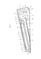
- the rotating shaft 91 consists of a metal rod having a hexagonal section, carrying rollers 115 and 116 at its opposite ends, and carrying roller 117 at its centre.
- the rollers 115, 116 and 117 as shown in Figure 12, each have a central through-hole 133 of a hexagonal section, for accommodating shaft 91.
- the rollers 115 and 116 are respectively provided with crescent-shaped grooves 134 with which opposite ends of the pin 142 of a page sheet unit 14 engage when the page sheet unit 14 is inserted into the device, and a cut-away part 135, for allowing the pin 142 to escape from engagement, is formed over a portion of the circumference of the roller 117.
- roller 115 is formed as a cylinder and page sheet unit identification hole 136 and page sheet identification holes 137, 138 are formed through the circumferential wall of the roller 115 in lines around that wall.
- the page sheet identification holes 137, 138 are formed so as to oppose the page sheet identification holes 144, 145 formed on the base sheet 141 of a page sheet unit 14 when the unit is wound on the roller 115.
- Each page sheet unit identification hole 136 is located at a position along the same horizontal line (line longitudinal of roller 115) as a page sheet identification hole 137 of the same number as the hole 136.
- the page sheet identification holes 137 and 138 of the roller match respectively with holes 144 and 145 of the base sheet.
- Page sheet unit identification holes 143 of the page sheet 141 match page sheet unit identification holes 136 of the roller 115 corresponding thereto, and unnecessary holes in roller 115, which do not match with holes 143, are covered, because the base sheet 141 is composed of a non-transparent material. Thereby, the desired page sheet unit identification signal can be obtained.
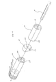
- the rollers 115,116,117 may be formed by a resin mould method, and loaded onto the rotating shaft 91 as shown in the perspective view and sectional view of Figures 13 and 14.
- the page unit rotation shaft is thus formed.
- the page sheet identification holes 137, 138 and 144, 145 match as explained above and therefore it is possible, as an alternative to the use of a page sheet unit as shown in Figure 6, to use a page sheet unit of a form such that the base sheet 141 shown in Figure 6 is cut along the line a-a' shown in Figure 6, so that page sheet identification holes 144, 145 are removed from the base sheet.
- Such a page sheet unit is rather effective from the point of view of strength of base sheet 141 because a more highly reliable identification signal can be obtained.
- the page selection mechanism of an embodiment of the present invention may be assembled as follows:- the holding plate 113, on which the pulleys 107, 108 and 109 are mounted, is directly mounted on the bottom plate 114. Thereafter, the drive shaft 92 is passed through the insertion hole 131 (for example, after insertion of gear 103). The rotating shaft 91 carrying the rollers 115, 116, 117 is arranged in parallel to the drive shaft 92 (with which it is engaged through the gears 104 and 105) and the drive shaft 92 and rotating shaft 91 are mounted on the holding plates 111 and 112 in such a manner that these shafts are supported so as to be freely rotatable.
- holding plates 111 and 112 are mounted on opposite ends of bottom plate 114, and the motor 100 is also installed. Thereafter, the holding plates 10 and 12 are installed in the slots 129 between the bottom plate 114 and holding plates 111, 112, and the belt 93 is bridged over the pulleys 106, 107, 108 and 109, and the timing belt 119 is bridged over the gears 102 and 103. Thereby the page selection mechanism can be assembled as shown in Figure 10.
- An item input device embodying the present invention can be attained by installing such a page selection mechanism into a cabinet as shown in Figure 2.
- a take-up operation for taking a page sheet unit 14 into the device, is effected as explained below.
- a desired page sheet unit 14 is first inserted into the guide path 13 extending from the exchange mouth, as shown in Figure 2, and it is set in a take-up ready condition by allowing the linkage pin 142 of base sheet 141 and the rotating shaft 91 to come into contact with one another.
- the one-way clutch 99 Since the one-way clutch 99 is so set that it rotates freely (not in mesh) for rotation of shaft 92 in direction a, the belt 93 does not rotate.
- the motor 100 is automatically driven in the reverse direction, and when the drive shaft 92 rotates in the direction indicated by arrow c, as shown in Figure 17, the one-way clutch 99 rotates in mesh, causing the pulley 106 to rotate in the direction indicated by arrow d.
- the belt 93 rotates in the direction indicated by arrows e and f
- the rotating shaft 91 also rotates in the reverse direction indicated by arrowg.
- the desired page sheet 140 moves in the direction indicated by arrow m whilst the other page sheets 140"' move in the direction indicated by arrow mark n.
- the one-way clutch 98 is set so that it rotates freely for rotation of the drive shaft 92 in the direction c.
- Figure 18 shows a condition in which the end of a first page sheet 140' (the end not fixed to base sheet 141) has moved past the guide plate 11 and is located in the guide path 13, and in which the end (the end not fixed to base sheet 141) of the last page sheet 140" is engaged behind the shaft 94.
- this condition is obtained in the page sheet unit 14 by virtue of the fact that the page sheet unit is set up in such a way, at the time of take-up, that the first page sheet 140' and the last page 140" are arranged as if a sheet had been removed from between them (that is, the length b mentioned above is equal to 2a).
- the page sheet unit 14 is taken-up by the rotating shaft 91 with its inner surface bearing on that shaft, whilst suffering a braking force exerted on its outer surfaces by the belt 93, so that no slack develops in the unit 14.
- the rotating shaft 91 is rotated in the reverse direction, by the belt 93 acting through the page sheet unit 14.
- the page sheet unit 14 (or a page sheet thereof) is fed out whilst the unit 14 is being pulled in the reverse direction around its circumference by the belt 93, and as a result the page sheet unit 14 is fed out smoothly without any slack developing.
- a pulling force exerted by the belt 93 generated at the time of page sheet feedout is obtained when the belt 93 rotates faster than the rotating shaft 91.
- such a pulling force can be obtained by setting the ratio of gear teeth between the gears 104 and 105 (the gear ratio) larger than the ratio of diameters of the pulley 106 and roller 117 (the pulley ratio).
- the gear ratio is always constant, but the pulley ratio changes as the effective diameter of roller 117 changes in dependence upon the amount of page sheet unit 14 taken up onto that roller. Therefore, the relationship between the pulley ratio and gear ratio is set so that the ratio between the two is almost 1:1 or so that the pulley ratio becomes a little larger than the gear ratio when the page sheet unit 14 is completely taken up onto the rotating shaft 91 (the roller 117 is at its thickest) and simultaneously the gear ratio becomes progressively larger than the pulley ratio as the diameter of the roller 117 gradually becomes smaller as a page sheet is fed out, from the timing where send of page sheet unit 14 is performed only for a while.
- the speed of rotation of belt 93 is almost equal to that of the rotating shaft, or the speed of rotation of shaft 91 is a little faster, but as page feed out proceeds the speed of rotation of the belt becomes faster than that of the rotating shaft 91.
- the speed of rotation of rotating shaft 91 is determined by the gear ratio of the gears 104 and 105 and is always constant.
- the rotating shaft 91 rotates in the reverse direction while suffering a braking force from the gears 104 and 105 for the reverse direction rotating force transmitted to the circumference of the page sheet unit 14 from the belt 93, and a difference of rotation speeds between the belt 93 and rotating shaft 91 is absorbed by slipping rotation of the belt 93 on the page sheet unit 14 which is taken up.
- the page sheet or the page sheet unit is fed out whilst it is being pulled by the rotating force of belt 93 applied to the rotating shaft 91 and receiving a braking force, and such pulling force operates as a tightening force on the page sheet unit 14 taken up.
- Figure 20 is a graph which illustrates the relationship between the number of page selecting operations effected and the displacement of ends of page sheets.
- a comparison is made between a preferred page selection mechanism embodying the present invention and other page selection mechanisms, on the basis of experimental results.
- the device whose characteristic is indicated by curve A has a structure in which page selection is effected by rotating a rotating shaft corresponding to shaft 91, in the winding direction and the reverse direction, by means only of a belt corresponding to belt 93.
- the device whose characteristics are indicated in curve B has a structure in which a rotating shaft corresponding to shaft 91 is directly connected to a motor corresponding to motor 100, and the rotating shaft is rotated in the winding direction and the reverse direction, for page selection, thereby.
- the device embodying the present invention, whose characteristics are indicated by curve C employs a page selection mechanism as explained above. Namely, at the time of page winding, the rotating shaft 91 rotates in the winding direction, but at the time of page selection, the rotating shaft is rotated in the reverse direction by means of belt 93.
- such displacement becomes as much as 3 mm after only 20 or 40 selection operations.
- the belt 93 which is used to hold the page sheet unit 14 in place when it is taken up, is provided substantially at the centre of rotating shaft 91 in the page selection mechanism of the present invention.
- a page sheet next to a desired page sheet 140 is held in place at one point by the pulley 107, and this page sheet can be reliably held thereby, ensuring stable page selection operations.
- two closed rotating force transmission paths are formed, using only one motor, and therefore the device can be provided in a compact and economic form with a reduced power consumption.
- Figure 21 is a schematic block diagram of a drive control circuit of an embodiment of the present invention, and in Figure 22 waveforms A to C illustrate relationships between drive pulses and page pulses.
- the drive control circuit 162 comprises a counter 163, a digital comparator 164, a drive pulse generator 165, and a motor drive circuit 166 for the motor 100.
- the drive pulse generator 165 generates voltage pulses with a constant period, as shown in waveform A of Figure 22, and applies these pulses to the motor drive circuit 166 and to counter 163.
- the motor drive circuit 166 drives the motor 100 in accordance with the drive pulses of waveform A of Figure 22.
- the motor being a pulse motor as explained above, provides a constant angle of rotation of the motor shaft for each drive pulse. Further, the total angle of rotation is proportional to the number of drive pulses.
- the motor shaft of motor 100 is coupled to the rotating shaft 91 via the belt 119, drive shaft 92, belt 93 and gears 104 and 105, and the angle of rotation of the rotating shaft 91 is thus proportional to the number of drive pulses sent to the motor drive circuit 166.
- the drive control circuit of Figure 22 has a structure in which drive pulses of the drive pulse generator 165 are input to a set terminal S of the counter circuit 163 and simultaneously the output pulses of flip-flop 158 are input to a reset terminal R of the counter 163, and a count value B sent from output terminal Q of counter 163 and a specified value A are compared by the digital comparator 164.
- A is smaller than B, the digital comparator 164 outputs a stop pulse to the drive pulse generator circuit 165 in order to stop its operation.
- the counter 163 is reset by output pulses (see waveforms B and C of Figure 2) of the flip-flop circuit 158 and sequentially counts succeeding drive pulses.
- Content B of the counter 163 is repeatedly compared with the specified value A, which is the preset number of drive pulses normally required between page pulses, by the digital comparator 164.
- the drive pulse generator 165 stops, causing the motor 100 to cease operation.
- the motor control means explained above is capable of preventing breakdown of a page sheet when an overload is applied to a page sheet for some reason, and is of considerable practical value.
Landscapes
- Engineering & Computer Science (AREA)
- General Engineering & Computer Science (AREA)
- Theoretical Computer Science (AREA)
- Human Computer Interaction (AREA)
- Physics & Mathematics (AREA)
- General Physics & Mathematics (AREA)
- Input From Keyboards Or The Like (AREA)
Claims (10)
Applications Claiming Priority (4)
| Application Number | Priority Date | Filing Date | Title |
|---|---|---|---|
| JP122789/80 | 1980-09-04 | ||
| JP122790/80 | 1980-09-04 | ||
| JP55122790A JPS5748171A (en) | 1980-09-04 | 1980-09-04 | Page switching device |
| JP55122789A JPS5748170A (en) | 1980-09-04 | 1980-09-04 | Page switching device |
Publications (2)
| Publication Number | Publication Date |
|---|---|
| EP0047606A1 EP0047606A1 (fr) | 1982-03-17 |
| EP0047606B1 true EP0047606B1 (fr) | 1985-07-31 |
Family
ID=26459840
Family Applications (1)
| Application Number | Title | Priority Date | Filing Date |
|---|---|---|---|
| EP81303862A Expired EP0047606B1 (fr) | 1980-09-04 | 1981-08-25 | Dispositif d'entrée dans un système de traitement de données |
Country Status (3)
| Country | Link |
|---|---|
| US (1) | US4498256A (fr) |
| EP (1) | EP0047606B1 (fr) |
| DE (1) | DE3171576D1 (fr) |
Families Citing this family (2)
| Publication number | Priority date | Publication date | Assignee | Title |
|---|---|---|---|---|
| GB2127598B (en) * | 1982-09-16 | 1986-02-12 | Daniel Lemuel Phillips | Keyboard attachment |
| US5233771A (en) * | 1992-05-15 | 1993-08-10 | Eesti Engineering, Llc | Selective banner-display device |
Family Cites Families (8)
| Publication number | Priority date | Publication date | Assignee | Title |
|---|---|---|---|---|
| US2116287A (en) * | 1934-03-05 | 1938-05-03 | Ericsson Telefon Ab L M | Sign display apparatus |
| US2552448A (en) * | 1948-03-01 | 1951-05-08 | Jens A Ortendahl | Selectable index |
| US3343149A (en) * | 1964-05-19 | 1967-09-19 | Rca Corp | Rotating random access card selection system |
| US3352042A (en) * | 1965-01-25 | 1967-11-14 | Eastman Kodak Co | Film storage system |
| US3756356A (en) * | 1971-12-14 | 1973-09-04 | Acme Visible Records Inc | Brake for manually operated rotary file |
| JPS5642772Y2 (fr) * | 1975-07-28 | 1981-10-06 | ||
| JPS5814686B2 (ja) * | 1978-04-07 | 1983-03-22 | シャープ株式会社 | 多項目入力装置 |
| JPS5629734A (en) * | 1979-06-21 | 1981-03-25 | Anritsu Corp | Input device for multi-item information |
-
1981
- 1981-08-14 US US06/292,913 patent/US4498256A/en not_active Expired - Fee Related
- 1981-08-25 EP EP81303862A patent/EP0047606B1/fr not_active Expired
- 1981-08-25 DE DE8181303862T patent/DE3171576D1/de not_active Expired
Also Published As
| Publication number | Publication date |
|---|---|
| DE3171576D1 (en) | 1985-09-05 |
| US4498256A (en) | 1985-02-12 |
| EP0047606A1 (fr) | 1982-03-17 |
Similar Documents
| Publication | Publication Date | Title |
|---|---|---|
| US4557617A (en) | Tape supply cartridge | |
| USRE43133E1 (en) | Tape-shaped label printing device | |
| US4678353A (en) | Tape supply cartridge | |
| EP0609107B1 (fr) | Mécanisme de réception de ruban | |
| US5186553A (en) | Printer and method | |
| US4773775A (en) | Tape-ribbon cartridge | |
| US4507668A (en) | Thermal printer | |
| US4865305A (en) | Paper sheet feeding apparatus | |
| EP0047606B1 (fr) | Dispositif d'entrée dans un système de traitement de données | |
| US5352048A (en) | Ink sheet cassette and recording apparatus capable of loading the ink sheet cassette | |
| CA1231327A (fr) | Dispositif de selection et d'entrainement de bandes enregistreuses | |
| JPS628809B2 (fr) | ||
| US4019617A (en) | Printing device | |
| JPS6214850B2 (fr) | ||
| JPS5936293B2 (ja) | 多項目情報入力装置 | |
| JPH0217806B2 (fr) | ||
| JPS5936290B2 (ja) | 多項目情報入力装置 | |
| JPS6150331B2 (fr) | ||
| EP0142108A2 (fr) | Cartouche pour bande d'impression et ruban d'encrage | |
| JPS6150330B2 (fr) | ||
| JPS5935051B2 (ja) | ペ−ジ切換装置の駆動制御方式 | |
| JPS5936292B2 (ja) | 多項目情報入力装置 | |
| JPS6127766B2 (fr) | ||
| KR860001518Y1 (ko) | 금전등록기의 감사용 페이퍼 구동장치 | |
| JPS5936291B2 (ja) | 多項目情報入力装置 |
Legal Events
| Date | Code | Title | Description |
|---|---|---|---|
| PUAI | Public reference made under article 153(3) epc to a published international application that has entered the european phase |
Free format text: ORIGINAL CODE: 0009012 |
|
| AK | Designated contracting states |
Designated state(s): DE FR GB |
|
| RBV | Designated contracting states (corrected) |
Designated state(s): DE FR GB SE |
|
| RBV | Designated contracting states (corrected) |
Designated state(s): DE FR GB |
|
| 17P | Request for examination filed |
Effective date: 19820908 |
|
| GRAA | (expected) grant |
Free format text: ORIGINAL CODE: 0009210 |
|
| AK | Designated contracting states |
Designated state(s): DE FR GB |
|
| REF | Corresponds to: |
Ref document number: 3171576 Country of ref document: DE Date of ref document: 19850905 |
|
| ET | Fr: translation filed | ||
| PLBE | No opposition filed within time limit |
Free format text: ORIGINAL CODE: 0009261 |
|
| STAA | Information on the status of an ep patent application or granted ep patent |
Free format text: STATUS: NO OPPOSITION FILED WITHIN TIME LIMIT |
|
| 26N | No opposition filed | ||
| PGFP | Annual fee paid to national office [announced via postgrant information from national office to epo] |
Ref country code: FR Payment date: 19950809 Year of fee payment: 15 |
|
| PGFP | Annual fee paid to national office [announced via postgrant information from national office to epo] |
Ref country code: GB Payment date: 19950814 Year of fee payment: 15 |
|
| PGFP | Annual fee paid to national office [announced via postgrant information from national office to epo] |
Ref country code: DE Payment date: 19950828 Year of fee payment: 15 |
|
| PG25 | Lapsed in a contracting state [announced via postgrant information from national office to epo] |
Ref country code: GB Effective date: 19960825 |
|
| GBPC | Gb: european patent ceased through non-payment of renewal fee |
Effective date: 19960825 |
|
| PG25 | Lapsed in a contracting state [announced via postgrant information from national office to epo] |
Ref country code: FR Effective date: 19970430 |
|
| PG25 | Lapsed in a contracting state [announced via postgrant information from national office to epo] |
Ref country code: DE Effective date: 19970501 |
|
| REG | Reference to a national code |
Ref country code: FR Ref legal event code: ST |