EP0049324B1 - Procédé et appareil pour la semi-cokéfaction de schiste bitumineux - Google Patents
Procédé et appareil pour la semi-cokéfaction de schiste bitumineux Download PDFInfo
- Publication number
- EP0049324B1 EP0049324B1 EP81104562A EP81104562A EP0049324B1 EP 0049324 B1 EP0049324 B1 EP 0049324B1 EP 81104562 A EP81104562 A EP 81104562A EP 81104562 A EP81104562 A EP 81104562A EP 0049324 B1 EP0049324 B1 EP 0049324B1
- Authority
- EP
- European Patent Office
- Prior art keywords
- distillation
- gas
- reactor
- oil shale
- smoldering
- Prior art date
- Legal status (The legal status is an assumption and is not a legal conclusion. Google has not performed a legal analysis and makes no representation as to the accuracy of the status listed.)
- Expired
Links
- 239000004058 oil shale Substances 0.000 title claims description 27
- 238000000034 method Methods 0.000 title claims description 22
- 238000009434 installation Methods 0.000 title 1
- 239000007789 gas Substances 0.000 claims description 65
- 229910052799 carbon Inorganic materials 0.000 claims description 17
- OKTJSMMVPCPJKN-UHFFFAOYSA-N Carbon Chemical compound [C] OKTJSMMVPCPJKN-UHFFFAOYSA-N 0.000 claims description 15
- 239000000428 dust Substances 0.000 claims description 9
- 238000010438 heat treatment Methods 0.000 claims description 8
- 238000002485 combustion reaction Methods 0.000 claims description 7
- QVGXLLKOCUKJST-UHFFFAOYSA-N atomic oxygen Chemical compound [O] QVGXLLKOCUKJST-UHFFFAOYSA-N 0.000 claims description 5
- 239000001301 oxygen Substances 0.000 claims description 5
- 229910052760 oxygen Inorganic materials 0.000 claims description 5
- 239000000567 combustion gas Substances 0.000 claims description 3
- 238000011043 electrofiltration Methods 0.000 claims description 3
- 238000004821 distillation Methods 0.000 claims 27
- 239000011343 solid material Substances 0.000 claims 2
- 102100025840 Coiled-coil domain-containing protein 86 Human genes 0.000 claims 1
- 101000932708 Homo sapiens Coiled-coil domain-containing protein 86 Proteins 0.000 claims 1
- LELOWRISYMNNSU-UHFFFAOYSA-N hydrogen cyanide Chemical compound N#C LELOWRISYMNNSU-UHFFFAOYSA-N 0.000 claims 1
- 238000003756 stirring Methods 0.000 claims 1
- 238000003763 carbonization Methods 0.000 description 31
- 239000007787 solid Substances 0.000 description 9
- 239000012159 carrier gas Substances 0.000 description 6
- 239000000463 material Substances 0.000 description 4
- 238000012545 processing Methods 0.000 description 4
- 238000012546 transfer Methods 0.000 description 4
- 238000001035 drying Methods 0.000 description 3
- 239000003546 flue gas Substances 0.000 description 3
- UGFAIRIUMAVXCW-UHFFFAOYSA-N Carbon monoxide Chemical compound [O+]#[C-] UGFAIRIUMAVXCW-UHFFFAOYSA-N 0.000 description 2
- 238000006243 chemical reaction Methods 0.000 description 2
- 239000000470 constituent Substances 0.000 description 2
- 238000001816 cooling Methods 0.000 description 2
- 238000005336 cracking Methods 0.000 description 2
- 238000000354 decomposition reaction Methods 0.000 description 2
- 229930195733 hydrocarbon Natural products 0.000 description 2
- 150000002430 hydrocarbons Chemical class 0.000 description 2
- 239000000203 mixture Substances 0.000 description 2
- 239000002245 particle Substances 0.000 description 2
- 238000000926 separation method Methods 0.000 description 2
- 239000010454 slate Substances 0.000 description 2
- 238000012360 testing method Methods 0.000 description 2
- 229910021532 Calcite Inorganic materials 0.000 description 1
- BVKZGUZCCUSVTD-UHFFFAOYSA-L Carbonate Chemical compound [O-]C([O-])=O BVKZGUZCCUSVTD-UHFFFAOYSA-L 0.000 description 1
- UFHFLCQGNIYNRP-UHFFFAOYSA-N Hydrogen Chemical compound [H][H] UFHFLCQGNIYNRP-UHFFFAOYSA-N 0.000 description 1
- 150000001721 carbon Chemical class 0.000 description 1
- 239000003575 carbonaceous material Substances 0.000 description 1
- 150000004649 carbonic acid derivatives Chemical group 0.000 description 1
- 239000000969 carrier Substances 0.000 description 1
- 230000006835 compression Effects 0.000 description 1
- 238000007906 compression Methods 0.000 description 1
- 238000009833 condensation Methods 0.000 description 1
- 230000005494 condensation Effects 0.000 description 1
- 238000007872 degassing Methods 0.000 description 1
- 230000008021 deposition Effects 0.000 description 1
- 230000006866 deterioration Effects 0.000 description 1
- 238000010790 dilution Methods 0.000 description 1
- 239000012895 dilution Substances 0.000 description 1
- 239000010459 dolomite Substances 0.000 description 1
- 229910000514 dolomite Inorganic materials 0.000 description 1
- 230000005684 electric field Effects 0.000 description 1
- 238000005367 electrostatic precipitation Methods 0.000 description 1
- 239000000835 fiber Substances 0.000 description 1
- 239000001257 hydrogen Substances 0.000 description 1
- 229910052739 hydrogen Inorganic materials 0.000 description 1
- 230000010354 integration Effects 0.000 description 1
- 239000007788 liquid Substances 0.000 description 1
- 239000003595 mist Substances 0.000 description 1
- 238000013021 overheating Methods 0.000 description 1
- JTJMJGYZQZDUJJ-UHFFFAOYSA-N phencyclidine Chemical class C1CCCCN1C1(C=2C=CC=CC=2)CCCCC1 JTJMJGYZQZDUJJ-UHFFFAOYSA-N 0.000 description 1
- 238000009656 pre-carbonization Methods 0.000 description 1
- 238000000197 pyrolysis Methods 0.000 description 1
- 238000012216 screening Methods 0.000 description 1
- 239000000126 substance Substances 0.000 description 1
- 230000008961 swelling Effects 0.000 description 1
- 238000010626 work up procedure Methods 0.000 description 1
Images

Classifications
-
- C—CHEMISTRY; METALLURGY
- C10—PETROLEUM, GAS OR COKE INDUSTRIES; TECHNICAL GASES CONTAINING CARBON MONOXIDE; FUELS; LUBRICANTS; PEAT
- C10G—CRACKING HYDROCARBON OILS; PRODUCTION OF LIQUID HYDROCARBON MIXTURES, e.g. BY DESTRUCTIVE HYDROGENATION, OLIGOMERISATION, POLYMERISATION; RECOVERY OF HYDROCARBON OILS FROM OIL-SHALE, OIL-SAND, OR GASES; REFINING MIXTURES MAINLY CONSISTING OF HYDROCARBONS; REFORMING OF NAPHTHA; MINERAL WAXES
- C10G1/00—Production of liquid hydrocarbon mixtures from oil-shale, oil-sand, or non-melting solid carbonaceous or similar materials, e.g. wood, coal
- C10G1/02—Production of liquid hydrocarbon mixtures from oil-shale, oil-sand, or non-melting solid carbonaceous or similar materials, e.g. wood, coal by distillation
-
- C—CHEMISTRY; METALLURGY
- C10—PETROLEUM, GAS OR COKE INDUSTRIES; TECHNICAL GASES CONTAINING CARBON MONOXIDE; FUELS; LUBRICANTS; PEAT
- C10B—DESTRUCTIVE DISTILLATION OF CARBONACEOUS MATERIALS FOR PRODUCTION OF GAS, COKE, TAR, OR SIMILAR MATERIALS
- C10B49/00—Destructive distillation of solid carbonaceous materials by direct heating with heat-carrying agents including the partial combustion of the solid material to be treated
- C10B49/02—Destructive distillation of solid carbonaceous materials by direct heating with heat-carrying agents including the partial combustion of the solid material to be treated with hot gases or vapours, e.g. hot gases obtained by partial combustion of the charge
- C10B49/04—Destructive distillation of solid carbonaceous materials by direct heating with heat-carrying agents including the partial combustion of the solid material to be treated with hot gases or vapours, e.g. hot gases obtained by partial combustion of the charge while moving the solid material to be treated
- C10B49/08—Destructive distillation of solid carbonaceous materials by direct heating with heat-carrying agents including the partial combustion of the solid material to be treated with hot gases or vapours, e.g. hot gases obtained by partial combustion of the charge while moving the solid material to be treated in dispersed form
-
- C—CHEMISTRY; METALLURGY
- C10—PETROLEUM, GAS OR COKE INDUSTRIES; TECHNICAL GASES CONTAINING CARBON MONOXIDE; FUELS; LUBRICANTS; PEAT
- C10B—DESTRUCTIVE DISTILLATION OF CARBONACEOUS MATERIALS FOR PRODUCTION OF GAS, COKE, TAR, OR SIMILAR MATERIALS
- C10B53/00—Destructive distillation, specially adapted for particular solid raw materials or solid raw materials in special form
- C10B53/06—Destructive distillation, specially adapted for particular solid raw materials or solid raw materials in special form of oil shale and/or or bituminous rocks
Definitions
- GB-A 668 808 describes a process for smoldering oil shale with a hot gas in a shaft furnace, the condensable constituents being separated from the smoldering gas, a proportion of the smoldering gas corresponding to the increase in the gas quantity being removed and the rest after heating up in the smoldering reactor is returned.
- the solid, still carbon-containing smoldering residue introduces an oxygen-containing gas, in particular air, into another part of the shaft furnace separated from the smoldering part in order to burn part of the carbon and to increase the temperature of the residue.
- the cooled, de-condensable gas is passed through the residue heated in this way, in order to heat it up again, whereupon it flows in countercurrent through the smoldering part of the smoldering furnace, where it causes the oil shale to smolder, and is then passed through fresh oil shale so that the oil contained in it after condensation at least partially condenses.
- the shaft furnace principle can no longer be used for finely shredded goods.
- Other methods using fines such as US-A 3 844 930 work with solids as heat carriers.
- the amount of solids to be handled is further increased by the amount of heat transfer medium which is a multiple of the amount of shale used.
- the carbonization gas mixed with the carrier gases is separated from the solids - heat transfer particles and carbonization residue.
- the smoldering gases are produced in dilution by the carrier gases, which makes their work-up more difficult.
- the smoldering residue leaves the cyclone in a mixture with the solid heat transfer media, so that larger amounts of ballast must also be carried along during its further processing.
- the smoldering temperatures are generally above 450 ° C and should not exceed 650 ° C, otherwise the reduction in yield due to cracking reactions cannot be avoided despite the short smoldering times. Temperatures between 470 and 550 ° C. are preferred.
- the attached Fig. 1 shows the yields in the cyclone swelling of a Schandelah oil shale compared to the yields according to the Fischer test.
- the oil shale used contained 10.3% by weight of organic carbon and had the following Fischer test yields:
- the carbonization gas is preheated to temperatures which are 150 to 250 K above the carbonization temperature.
- This overheating depends on the ratio of carbonization gas to oil shale, which is usually between 0.8 and 1.4 Nm 3 / kg, preferably between 1.0 and 1.2 Nm 3 / kg lies on the temperature of the slate used, on the residual moisture, on the carbonate decomposition of the carbonates contained, and on the heat losses of the system.
- coarser feed material can be used in the method according to the invention than in the known method. Oil shale with a grain size of up to 3 mm, even up to 5 mm, can be used. These coarse-grained slates have the advantage of containing less dust, which considerably facilitates both the processing of the carbonization gas and the further treatment of the carbonization residue.
- the condensable components are separated from the carbonization gas by cooling it directly with cold oil, possibly with subsequent electrostatic precipitation of the oil mist.
- deposition by means of electrofiltration has proven to be particularly expedient. This is quite surprising, because it was not to be expected that the high temperatures of more than 450 ° C would allow electrofiltration of the carbonization gases, since the electrical field would collapse in a reducing atmosphere without the presence of sulfuric vapors.
- the smoldering residue is withdrawn from the cyclone reactor; its carbon is expediently burned with oxygen-containing gases, in particular air, it being possible for the hot combustion gas to be used for preheating the circulating carbonization gas.
- the carbon of the carbonization residue is expediently burned with oxygen-containing gases in a fluidized bed.
- the combustion conditions must be set so that S0 2 produced during combustion is integrated into the residue due to dolomite and calcite which may be found in the shale.
- the smoldering residue discharged from the smoldering cyclone reactor can first be degassed in a container before its carbon is burned with oxygen-containing gases.
- smoldering gas can be passed through for faster removal of the gases still present, it being expedient to loosen up the smoldering residue with stirrers or to shift it in a rotating drum.
- the known device in which the gas discharge of the smoldering reactor is connected to an oil separator and the inlet connector of the smoldering reactor is connected to the oil separator via a blower, has a cyclone reactor with a tangential inlet connector and a heat exchanger between the blower and the tangential inlet connector of the smoldering cyclone reactor for carrying out the method according to the invention .
- a preheater for the oil shale to be smoldered is preferably provided in front of the tangential inlet connection of the smoldering cyclone reactor.
- a dust separator operating at temperatures of the dew point of the carbonization gases in particular an electrostatic filter, is arranged between the carbonization cyclone reactor and the oil separator.
- the solids discharge of the smoldering cyclone reactor is connected to a combustion furnace and its hot gas outlet is connected to the heat exchanger provided for heating the smoldering gas serving as carrier gas. It has also proven to be expedient to provide a post-carbonization drum on the solid discharge port of the smoldering cyclone reactor or between this discharge port and the combustion device for smoldering residue.
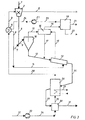
- a device according to the invention is shown schematically in the attached FIG. 3.
- the method according to the invention is explained on the basis of this:
- the oil shale 1 is comminuted to a grain size of less than 3 mm.
- the comminution and screening is expediently carried out together with the drying and preheating in a mill dryer 2, for which purpose the flue gases 3 are used after the cycle gas preheater 4.
- the cooled flue gas is discharged via line 5.
- the crushed, dried and preheated oil shale 6 to approx. 110 ° C is mixed in the riser 7 with circulating hot gas 8, a substantial part of the heat being transferred from the heating gas to the slate in the riser pipe, and this mixture via the tangential feed 9 in led the smoldering cyclone 10.
- the oil and dust-containing carbonization gases leave the carbonization cyclone 10 via line 11, while the carbonization residue is fed via line 12 into a re-carbonation drum 13.
- part of the hot recycle gas is passed through line 14 into the re-carbonation drum 13.
- the smoldering and cycle gas 15 from the after-carbonization 13 is led together with the smoldering gases 11 from the smoldering cyclone into a dedusting system 16.
- the separated dust is fed via line 17 into the post-carbon drum 13.
- the dedusted gas passes through the pipeline 18 into the oil separator 19, where it is freed of the condensable fractions which are supplied as product via the line 20 to the further processing.
- From the oil separation 19, a part of the smoldering gas corresponding to the amount of gas obtained during the pre-carbonization is likewise produced as a product via the line 21 dissipated.
- the remaining carbonization gas is fed via line 22 to the compressor 23 and, after compression through line 24, reaches the cycle gas preheater 4.
- the hot smoldering residue 25 behind the post-carbonization drum 13 is fed to a fluidized bed incinerator 26, in which the residual carbon is burned off.
- the temperature control for setting the optimal SO 2 integration is carried out by the heat exchanger 27 in the fluidized bed, which is designed as a steam generator.
- the hot flue gas leaves the fluidized bed furnace via line 28.
- the heat content of this gas is used in the cycle gas heat exchanger 4 for smoldering and in mill drying 2 for drying and preheating the oil shale.
- the burned-off oil shale from the fluidized bed furnace is fed through line 29 to a cooler 30 and leaves the cooler via line 31.
- the combustion air 32 which is compressed in the compressor 33, is led via line 34 to the cooler 30 and via the line 35 reaches the fluidized bed furnace 26.
Landscapes
- Chemical & Material Sciences (AREA)
- Engineering & Computer Science (AREA)
- Oil, Petroleum & Natural Gas (AREA)
- Organic Chemistry (AREA)
- Materials Engineering (AREA)
- Chemical Kinetics & Catalysis (AREA)
- General Chemical & Material Sciences (AREA)
- Combustion & Propulsion (AREA)
- Life Sciences & Earth Sciences (AREA)
- Wood Science & Technology (AREA)
- Dispersion Chemistry (AREA)
- Production Of Liquid Hydrocarbon Mixture For Refining Petroleum (AREA)
Claims (15)
Applications Claiming Priority (2)
| Application Number | Priority Date | Filing Date | Title |
|---|---|---|---|
| DE3023670 | 1980-06-25 | ||
| DE3023670A DE3023670C2 (de) | 1980-06-25 | 1980-06-25 | Verfahren und Vorrichtung zum Schwelen von Ölschiefer |
Publications (2)
| Publication Number | Publication Date |
|---|---|
| EP0049324A1 EP0049324A1 (fr) | 1982-04-14 |
| EP0049324B1 true EP0049324B1 (fr) | 1984-09-12 |
Family
ID=6105369
Family Applications (1)
| Application Number | Title | Priority Date | Filing Date |
|---|---|---|---|
| EP81104562A Expired EP0049324B1 (fr) | 1980-06-25 | 1981-06-13 | Procédé et appareil pour la semi-cokéfaction de schiste bitumineux |
Country Status (9)
| Country | Link |
|---|---|
| US (1) | US4388173A (fr) |
| EP (1) | EP0049324B1 (fr) |
| AU (1) | AU545951B2 (fr) |
| BR (1) | BR8103968A (fr) |
| DE (2) | DE3023670C2 (fr) |
| ES (1) | ES8207580A1 (fr) |
| JO (1) | JO1113B1 (fr) |
| MA (1) | MA19167A1 (fr) |
| YU (1) | YU42719B (fr) |
Families Citing this family (10)
| Publication number | Priority date | Publication date | Assignee | Title |
|---|---|---|---|---|
| BR8302810A (pt) * | 1983-05-27 | 1985-01-15 | Petroleo Brasileiro Sa | Processo para a retornagem de solidos contendo hidrocarbonetos |
| DE3323770A1 (de) * | 1983-07-01 | 1985-01-03 | Metallgesellschaft Ag, 6000 Frankfurt | Verfahren zum trocknen und erhitzen von oelhaltigen feststoffen |
| US4585543A (en) * | 1984-03-09 | 1986-04-29 | Stone & Webster Engineering Corp. | Method for recovering hydrocarbons from solids |
| US4601812A (en) * | 1985-01-07 | 1986-07-22 | Conoco Inc. | Oil shale retorting process |
| DE3715158C1 (de) * | 1987-05-07 | 1988-09-15 | Veba Oel Entwicklungs Gmbh | Verfahren zur Gewinnung von Schweloel |
| GB2276631A (en) * | 1993-02-24 | 1994-10-05 | Great Eastern | Process for removal of petroleum contaminants from particulate materials |
| CA2546940C (fr) * | 2006-05-15 | 2010-09-21 | Olav Ellingsen | Processus de recuperation et de craquage/d'amelioration simultanes du petrole a partir de materiaux solides |
| US10030199B2 (en) * | 2007-11-23 | 2018-07-24 | Bixby Energy Systems, Inc. | Pyrolisis apparatus |
| US9795972B2 (en) | 2012-08-07 | 2017-10-24 | Cameron International Corporation | High temperature high pressure electrostatic treater |
| CN104745221B (zh) * | 2015-04-01 | 2016-04-27 | 曲靖众一精细化工股份有限公司 | 一种细、小颗粒干馏油气高品质回收方法及其回收装置 |
Family Cites Families (21)
| Publication number | Priority date | Publication date | Assignee | Title |
|---|---|---|---|---|
| US2414586A (en) * | 1942-09-05 | 1947-01-21 | Universal Oil Prod Co | Distillation of hydrocarbonaceous solids |
| US2434567A (en) * | 1944-01-19 | 1948-01-13 | Standard Oil Dev Co | Method and apparatus for contacting hydrocarbons with catalyst particles |
| GB668808A (en) * | 1949-09-17 | 1952-03-19 | California Research Corp | Process for retorting shale |
| DE1160823B (de) * | 1954-10-14 | 1964-01-09 | Kloeckner Humboldt Deutz Ag | Verfahren zum kontinuierlichen Entgasen, wie Schwelen und/oder Verkoken, von feinkoernigen, nicht backenden, wasserhaltigen Brennstoffen mittels heisser Gasstroeme |
| US2942043A (en) * | 1955-01-03 | 1960-06-21 | Hoechst Ag | Process for carrying out endothermic chemical reactions |
| US3475319A (en) * | 1966-12-22 | 1969-10-28 | Exxon Research Engineering Co | Retorting of oil shale |
| DE1809874B2 (de) * | 1968-11-20 | 1974-10-31 | Metallgesellschaft Ag, 6000 Frankfurt | Vorrichtung zur trockenen Destillation von bituminösen oder ölhaltigen, feinkörnigen Materialien zwecks Gewinnung von flüssigen Kohlenwasserstoffen |
| US3577338A (en) * | 1969-02-19 | 1971-05-04 | Phillip H Gifford | Process for recovery of oil from oil shale simultaneously producing hydrogen |
| GB1326455A (en) * | 1971-01-26 | 1973-08-15 | Texaco Development Corp | Hydrotorting of shale to produce shale oil |
| BR7105857D0 (pt) * | 1971-09-06 | 1973-04-10 | Brasileiros Sa Petrob Petroleo | Processo aprefeicoado para obtencao de oleo gas e subprodutos de xisto pirobetuminosos ou outros materiais impregnados com hidrocarbonetos |
| DE2244753B1 (de) * | 1972-09-08 | 1973-10-18 | Mannesmann Ag, 4000 Duesseldorf | Verfahren und Vorrichtung zur Ver mchtung von Mull |
| US4003797A (en) * | 1976-05-05 | 1977-01-18 | Union Oil Company Of California | Superatmospheric pressure shale retorting process |
| US4066529A (en) * | 1976-05-07 | 1978-01-03 | Paraho Corporation | Method of design for vertical oil shale retorting vessels and retorting therewith |
| DE2728455A1 (de) * | 1976-06-25 | 1978-01-05 | Occidental Res Corp | Verfahren und vorrichtung zum pyrolysieren von kohlenstoffhaltigem material |
| US4105502A (en) * | 1976-06-25 | 1978-08-08 | Occidental Petroleum Corporation | Simplified liquefaction pyrolysis process and apparatus therefor |
| DE2637427C3 (de) * | 1976-08-20 | 1980-04-03 | Metallgesellschaft Ag, 6000 Frankfurt | Verfahren zum Erhitzen von feinkernigem, kohlenstoffhaltigem Material |
| US4118309A (en) * | 1976-12-10 | 1978-10-03 | Atlantic Richfield Company | Separation and recovery of heat carriers in an oil shale retorting process |
| GB1567115A (en) * | 1978-02-28 | 1980-05-08 | Shale Oil Science & Systems In | Method and apparatus for processing solid materials such as oil shale |
| US4199432A (en) * | 1978-03-22 | 1980-04-22 | Chevron Research Company | Staged turbulent bed retorting process |
| US4222850A (en) * | 1979-02-15 | 1980-09-16 | Gulf Research & Development Company | Process for retorting oil shale |
| DE2923048C2 (de) * | 1979-06-07 | 1984-11-08 | Rheinische Braunkohlenwerke AG, 5000 Köln | Verfahren zum Schwelen von Ölschiefer oder Teersand in Gegenwart von Wasserstoff |
-
1980
- 1980-06-25 DE DE3023670A patent/DE3023670C2/de not_active Expired
-
1981
- 1981-05-19 YU YU1294/81A patent/YU42719B/xx unknown
- 1981-06-01 MA MA19376A patent/MA19167A1/fr unknown
- 1981-06-12 AU AU71670/81A patent/AU545951B2/en not_active Ceased
- 1981-06-13 EP EP81104562A patent/EP0049324B1/fr not_active Expired
- 1981-06-13 DE DE8181104562T patent/DE3165997D1/de not_active Expired
- 1981-06-16 JO JO19811113A patent/JO1113B1/en active
- 1981-06-23 ES ES503316A patent/ES8207580A1/es not_active Expired
- 1981-06-24 US US06/277,001 patent/US4388173A/en not_active Expired - Fee Related
- 1981-06-24 BR BR8103968A patent/BR8103968A/pt unknown
Also Published As
| Publication number | Publication date |
|---|---|
| YU129481A (en) | 1983-12-31 |
| EP0049324A1 (fr) | 1982-04-14 |
| DE3023670C2 (de) | 1982-12-23 |
| YU42719B (en) | 1988-12-31 |
| DE3023670A1 (de) | 1982-01-14 |
| JO1113B1 (en) | 1982-07-10 |
| ES503316A0 (es) | 1982-10-01 |
| BR8103968A (pt) | 1982-03-09 |
| AU545951B2 (en) | 1985-08-08 |
| US4388173A (en) | 1983-06-14 |
| ES8207580A1 (es) | 1982-10-01 |
| DE3165997D1 (en) | 1984-10-18 |
| AU7167081A (en) | 1982-01-07 |
| MA19167A1 (fr) | 1981-12-31 |
Similar Documents
| Publication | Publication Date | Title |
|---|---|---|
| DE69114294T2 (de) | Wiederverwendungsverfahren, apparat und produkt hergestellt in diesem verfahren zur gewinnung eines extenders oder weichmachers für gummi aus automobilaltreifen. | |
| DE1909263C3 (de) | Verfahren und Vorrichtung zum Schwelen von feinkörnigen bituminösen Stoffen, die einen staubförmigen Schwelrückstand bilden | |
| DE2621941C3 (de) | Verfahren zur Herstellung von Kohle und Kohlenwasserstoffdämpfen aus Gummi durch thermische Zersetzung | |
| DE3344847C2 (de) | Schnell-Pyrolyse von Braunkohlen und Anordnung zur Durchführung dieses Verfahrens | |
| DE1809874B2 (de) | Vorrichtung zur trockenen Destillation von bituminösen oder ölhaltigen, feinkörnigen Materialien zwecks Gewinnung von flüssigen Kohlenwasserstoffen | |
| EP0049324B1 (fr) | Procédé et appareil pour la semi-cokéfaction de schiste bitumineux | |
| DE2532778C3 (de) | Verfahren zum Vorwärmen von ölschiefer vor dessen Pyrolyse | |
| EP3081622A1 (fr) | Procédé et installation destinés à améliorer la production de goudrons de pyrolyse | |
| DE1470604A1 (de) | Verfahren zur OElgewinnung aus kohlenwasserstoffhaltigen Stoffen | |
| DE2640508A1 (de) | Verfahren zum betrieb von zweistufigen kohleflugstromtrocknern | |
| WO1996021824A1 (fr) | Procede de traitement thermique de dechets | |
| DE3237791A1 (de) | Mehrstufiges verfahren und einrichtung zum trocknen von teilchenfoermigem kohlenstoffhaltigem material | |
| DD141056A5 (de) | Verfahren und vorrichtung zur aufbereitung und verbrennung von kohle | |
| EP0116180B1 (fr) | Procédé pour la cokéfaction partielle de résidus d'hydrogénation | |
| DE69100682T3 (de) | Verfahren und Vorrichtung zur Herstellung von einem festen Brennstoff ausgehend von brennbaren Abfällen. | |
| DE3220229A1 (de) | Verfahren zur herstellung eines an wasserstoff und kohlenmonoxid reichen gasstroms aus kohle | |
| DE2947346C2 (de) | Verfahren zur Gewinnung von Aktivkohle oder Koks und Trommelofen zur Durchführung des Verfahrens | |
| DE69732164T2 (de) | Thermisches Gerät und Verfahren zum Entfernen von Verunreinigungen aus Öl | |
| DE2415412A1 (de) | Verfahren und vorrichtung zur behandlung hochmolekularer hydrocarbonate oder altoele | |
| DE3323770C2 (fr) | ||
| DE3305994C2 (fr) | ||
| DE1160823B (de) | Verfahren zum kontinuierlichen Entgasen, wie Schwelen und/oder Verkoken, von feinkoernigen, nicht backenden, wasserhaltigen Brennstoffen mittels heisser Gasstroeme | |
| DE2537732B2 (de) | Verfahren zur thermischen Verarbeitung von festen bituminösen Stoffen | |
| EP0068524B1 (fr) | Procédé pour la récupération d'huile à partir de minéraux contenant de l'huile | |
| DE2516745C3 (de) | Verfahren zur Verschwelung von Kohle |
Legal Events
| Date | Code | Title | Description |
|---|---|---|---|
| PUAI | Public reference made under article 153(3) epc to a published international application that has entered the european phase |
Free format text: ORIGINAL CODE: 0009012 |
|
| AK | Designated contracting states |
Designated state(s): DE FR GB IT SE |
|
| 17P | Request for examination filed |
Effective date: 19820611 |
|
| ITF | It: translation for a ep patent filed | ||
| GRAA | (expected) grant |
Free format text: ORIGINAL CODE: 0009210 |
|
| AK | Designated contracting states |
Designated state(s): DE FR GB IT SE |
|
| REF | Corresponds to: |
Ref document number: 3165997 Country of ref document: DE Date of ref document: 19841018 |
|
| ET | Fr: translation filed | ||
| PLBE | No opposition filed within time limit |
Free format text: ORIGINAL CODE: 0009261 |
|
| STAA | Information on the status of an ep patent application or granted ep patent |
Free format text: STATUS: NO OPPOSITION FILED WITHIN TIME LIMIT |
|
| 26N | No opposition filed | ||
| PG25 | Lapsed in a contracting state [announced via postgrant information from national office to epo] |
Ref country code: GB Effective date: 19890613 |
|
| GBPC | Gb: european patent ceased through non-payment of renewal fee | ||
| PGFP | Annual fee paid to national office [announced via postgrant information from national office to epo] |
Ref country code: FR Payment date: 19900629 Year of fee payment: 10 |
|
| PG25 | Lapsed in a contracting state [announced via postgrant information from national office to epo] |
Ref country code: FR Effective date: 19920228 |
|
| REG | Reference to a national code |
Ref country code: FR Ref legal event code: ST |
|
| PGFP | Annual fee paid to national office [announced via postgrant information from national office to epo] |
Ref country code: SE Payment date: 19930507 Year of fee payment: 13 |
|
| PGFP | Annual fee paid to national office [announced via postgrant information from national office to epo] |
Ref country code: DE Payment date: 19930611 Year of fee payment: 13 |
|
| PG25 | Lapsed in a contracting state [announced via postgrant information from national office to epo] |
Ref country code: SE Effective date: 19940614 |
|
| EUG | Se: european patent has lapsed |
Ref document number: 81104562.4 Effective date: 19950110 |
|
| PG25 | Lapsed in a contracting state [announced via postgrant information from national office to epo] |
Ref country code: DE Effective date: 19950301 |
|
| EUG | Se: european patent has lapsed |
Ref document number: 81104562.4 |