EP0055498A1 - Procédé et dispositif de surveillance sélective à distance contre les court-circuits pour lignes électriques - Google Patents
Procédé et dispositif de surveillance sélective à distance contre les court-circuits pour lignes électriques Download PDFInfo
- Publication number
- EP0055498A1 EP0055498A1 EP81201321A EP81201321A EP0055498A1 EP 0055498 A1 EP0055498 A1 EP 0055498A1 EP 81201321 A EP81201321 A EP 81201321A EP 81201321 A EP81201321 A EP 81201321A EP 0055498 A1 EP0055498 A1 EP 0055498A1
- Authority
- EP
- European Patent Office
- Prior art keywords
- phase
- reference signals
- limit
- voltage
- circuit
- Prior art date
- Legal status (The legal status is an assumption and is not a legal conclusion. Google has not performed a legal analysis and makes no representation as to the accuracy of the status listed.)
- Ceased
Links
- 238000000034 method Methods 0.000 title claims description 9
- 238000012544 monitoring process Methods 0.000 claims abstract description 11
- 238000005259 measurement Methods 0.000 claims abstract description 4
- 230000010363 phase shift Effects 0.000 claims 2
- 239000013598 vector Substances 0.000 description 13
- 238000010586 diagram Methods 0.000 description 4
- 239000004020 conductor Substances 0.000 description 3
- 238000011156 evaluation Methods 0.000 description 3
- 230000015572 biosynthetic process Effects 0.000 description 2
- 238000009795 derivation Methods 0.000 description 2
- 238000004804 winding Methods 0.000 description 2
- 239000003990 capacitor Substances 0.000 description 1
- 238000010276 construction Methods 0.000 description 1
- 238000006073 displacement reaction Methods 0.000 description 1
- 230000010355 oscillation Effects 0.000 description 1
- 238000010079 rubber tapping Methods 0.000 description 1
Images

Classifications
-
- H—ELECTRICITY
- H02—GENERATION; CONVERSION OR DISTRIBUTION OF ELECTRIC POWER
- H02H—EMERGENCY PROTECTIVE CIRCUIT ARRANGEMENTS
- H02H3/00—Emergency protective circuit arrangements for automatic disconnection directly responsive to an undesired change from normal electric working condition with or without subsequent reconnection ; integrated protection
- H02H3/38—Emergency protective circuit arrangements for automatic disconnection directly responsive to an undesired change from normal electric working condition with or without subsequent reconnection ; integrated protection responsive to both voltage and current; responsive to phase angle between voltage and current
- H02H3/382—Emergency protective circuit arrangements for automatic disconnection directly responsive to an undesired change from normal electric working condition with or without subsequent reconnection ; integrated protection responsive to both voltage and current; responsive to phase angle between voltage and current involving phase comparison between current and voltage or between values derived from current and voltage
Definitions
- the invention relates to a method according to the preamble of claim 1 and to a device for performing the method.
- a method and a corresponding device for short-circuit monitoring of the aforementioned type is known from DE-PS 1 947 037.
- the reactance limit that is to say the limit or boundary sections of the triggering area which determine the extent of the triggering area in the direction of the reactance axis of the impedance plane
- the resistance limit that is to say which essentially determine the extent of the triggering area in the direction of the resistance axis of the impedance level Boundary or boundary sections
- two reference signals phase-shifted with respect to one another, each with an associated current transformer and phase shifter.
- the corresponding differential signals with the line voltage provided different voltage transformer secondary windings.
- the resulting circuit complexity is also to be provided in the case of multiple use with selection switching of a measuring system for different conductors or phases of a multiphase line system for the different conductors.
- the object of the invention is to eliminate the disadvantages of the known and to provide a short circuit monitoring method and a corresponding device which allow a polygonal triggering area to be implemented with comparatively little circuit complexity and at the same time ensure the directional decision.
- the invention as characterized in the claims, achieves the object. Although a more complex circuit is required, the directional decision is clear even in the case of very close faults, because the use of the so-called healthy voltage, which is foreign to the short circuit, enables a characteristic from which the directional decision can be easily determined.
- the object of the invention can also be used in the case of near three-pole faults.
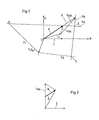
- the vector of the line current I lies as a phase angle reference in the real axis, while the line voltage U forms an angle with the latter depending on the operating or fault condition.
- the trigger area is determined by the corner points 1, 2, 3 and 4. A position of the vector of the line voltage U within this trigger area represents the error criterion, while a position of the vector peak of U outside the trigger limits, ie the straight line sections between the mentioned corner points, indicates a non-faulty operating state.
- the straight line G X delimiting the trigger area essentially in the direction of the imaginary axis is referred to as the reactance limit
- the straight line G R delimiting the trigger area essentially in the direction of the real axis is referred to as the resistance limit.
- the boundaries Z 1 and Z 2 which do not run through the coordinate zero point and are only slightly inclined towards X or R, essentially have the function of determining the direction of the power flow with respect to the measurement location on the line and are referred to as direction boundaries.
- SLe also guarantee the directional decision. Due to the dependence of the line voltage vector U according to the amount and direction of the distance of the fault location from the measurement location, the distance selectivity of the triggering criterion results.
- the in-phase reference signals A and B are formed with a fixed phase position with respect to the line current 1 and the same amplitudes, and furthermore, using the line voltage U associated differential signals U dA and U dB .
- the phase angles of these difference signals are compared with predetermined limit phase angles, it is possible to obtain unambiguous statements about the position of the vector peak of U within or outside that limit - G R or G X - which is derived from the vector peak of the reference signal - A or B - associated with the relevant difference signal. runs.
- the limit phase angle for U dA is chosen to be approximately zero with respect to R or I
- the limit running through the tip of A is defined as the reactance limit - hence designated Gx in the example. If, however, about the boundary phase angles for U dA approximately with respect to R or in relation to selected X at 90 0 zero, so that the line passing through the tip of A limit is defined as Resistanzalia.
- the limit running through the tip of B which in the example is obtained with a limit phase angle of approximately zero with respect to X or 90 ° with respect to R for the limit phase comparison of U dB and therefore represents the resistance limit G.
- any directions of the two limits between the mentioned cases can be set, although there is generally no longer any unambiguous assignment to the limitation of the triggering area in the reactance or resistance direction.
- triggering limits that are arbitrarily arranged and directed and that do not pass through the coordinate zero point can thus be realized with reference signals in phase.
- in-phase reference signals A, B from the output voltage U W, which is essentially perpendicular to the line current I, of a conventional current-voltage converter by tapping between the sub-voltages of U W on the one hand and the sub-voltages (not specified in more detail) of a conventional one , orthogonal phase shifter on the other hand.
- the phase position of A and B can be set without changing the amplitude when the tap is on half of U is done.
- the circuit shown in FIG. 3 realizes the acquisition of A and B according to FIG. 2 by means of only one current measuring channel in the form of a current-voltage converter WI with a center tap on the secondary side and a phase changer arranged downstream from a potentiometer P and a capacitor C.
- a common, phase-determining output variable for the formation of the two reference signals is taken between the center tap of the secondary winding of the current-voltage converter WI on the one hand and the circuit point between P and C on the other hand, and two amplifiers V A and V B with downstream potentiometers P A and P B are fed in parallel as amplitude-determining elements whose taps are the in-phase reference signals A and B with a selectable amplitude.
- the difference signals U dA and U dB result from interconnecting A and B with the line voltage U obtained via a voltage converter WU R and are each fed to a phase comparator DX or DR.
- Two further voltage converters WU S , WU T are connected to the direction measuring element DC via a mixing stage M.
- the limit phase angles which, as explained above, determine the direction of the reactance and resistance limit G X or G R , are obtained from a common reference signal in phase rotators which are conventional per se and are therefore not shown in any more detail (for the sake of simplicity also designated G X and G R ) derived, in the example from the reference signal A. In principle, however, any other signal with a defined phase position relative to the line current I, such as the output signal of the current-voltage converter itself, can be considered as the reference signal for obtaining the limit phase angle.
- the limit phase angle monitoring is carried out in the phase comparators DX and DR in the sense that a binary signal is given to an evaluation logic AL depending on a position of the vector peak of U inside or outside of G x or G R.
- the latter also receives a binary signal depending on the phase position of the line voltage U within or outside the smaller angle (open towards the triggering area) between the directional limits Z 1 and Z 2 , which are also determined by corresponding reference signals or vectors.
- the latter are derived from the phase position of the reference signals A, B in two phase shifters, designated Z ' 1 and Z' 2 , namely from the input of the amplifiers V A , V B.
- a direction measuring element DZ which receives the voltage U G in addition to Z ' 1 and Z' 2 outputs, carries out the phase comparison in accordance with the direction of U G with respect to Z 1 and Z 2 and feeds the already mentioned direction binary signal to the evaluation logic AL .
- the voltage U G is a short-circuit voltage. It offers the following advantages: Clear decision in the case of very close faults and when the high-voltage converters are capacitive converters. In the case of a three-pole short circuit, the voltage U G can be replaced by a voltage stored before the short circuit.
- the evaluation logic AL essentially carries out a conjunctive overall linkage of the supplied binary signals and delivers at its output an identification signal for the position of the vector peak of U inside or outside the tripping region, which is now limited on all sides.
- a particular advantage of the circuit shown is that only one current measuring channel is required for a measuring system that completely defines the polygonal triggering area. That means an essential mind tion of the circuitry.
- the connection of only a simple phase shifter to the current transformer makes it easier to use current-voltage transformers with an air gap as input transformers.
- These converters are advantageous in themselves because of the lower oversizing factor, but make it more difficult to use reference impedances with different and especially those with a small phase angle. This circuitry overcomes this difficulty.
- Another advantage is the derivation of the limit phase angle used in the example from the output of the phase-rotating element on the input converter and in particular from the reference signals A or B or from only one of them.
- this measure enables an extremely simple switching of the measuring system, i.e. the inputs of the amplifiers V and V B and the line voltage input EU and the point EM, between different converter sets of associated phase conductors of a multiphase system depending on the error-related selection.
- the corresponding switchover points which evidently comprise only a few measuring lines and corresponding contacts, are only indicated schematically in FIG. 3 and are designated AS.
- FIG. 4 is another example embodiment shown the inventive device.
- the circuit corresponds in part to that according to FIG. 3, but a second mixing stage M 2 is arranged instead of the phase rotators Z ' 1 , Z' 2 . This improves the relay behavior with regard to oscillation.
Landscapes
- Emergency Protection Circuit Devices (AREA)
Applications Claiming Priority (2)
| Application Number | Priority Date | Filing Date | Title |
|---|---|---|---|
| CH9516/80 | 1980-12-23 | ||
| CH951680 | 1980-12-23 |
Publications (1)
| Publication Number | Publication Date |
|---|---|
| EP0055498A1 true EP0055498A1 (fr) | 1982-07-07 |
Family
ID=4352814
Family Applications (1)
| Application Number | Title | Priority Date | Filing Date |
|---|---|---|---|
| EP81201321A Ceased EP0055498A1 (fr) | 1980-12-23 | 1981-12-03 | Procédé et dispositif de surveillance sélective à distance contre les court-circuits pour lignes électriques |
Country Status (1)
| Country | Link |
|---|---|
| EP (1) | EP0055498A1 (fr) |
Cited By (2)
| Publication number | Priority date | Publication date | Assignee | Title |
|---|---|---|---|---|
| EP0115017A1 (fr) * | 1982-12-28 | 1984-08-08 | Kabushiki Kaisha Toshiba | Méthode et système pour indiquer la direction d'un défaut |
| US8538611B2 (en) * | 2003-01-06 | 2013-09-17 | General Electric Company | Multi-level railway operations optimization system and method |
Citations (2)
| Publication number | Priority date | Publication date | Assignee | Title |
|---|---|---|---|---|
| DE1947037A1 (de) * | 1969-09-12 | 1971-03-18 | Siemens Ag | Distanzschutzeinrichtung mit polygonalem Ausloesegebiet |
| GB2004143A (en) * | 1977-09-06 | 1979-03-21 | Bbc Brown Boveri & Cie | Method and apparatus for the distance-selective fault monitoring of electrical lines |
-
1981
- 1981-12-03 EP EP81201321A patent/EP0055498A1/fr not_active Ceased
Patent Citations (2)
| Publication number | Priority date | Publication date | Assignee | Title |
|---|---|---|---|---|
| DE1947037A1 (de) * | 1969-09-12 | 1971-03-18 | Siemens Ag | Distanzschutzeinrichtung mit polygonalem Ausloesegebiet |
| GB2004143A (en) * | 1977-09-06 | 1979-03-21 | Bbc Brown Boveri & Cie | Method and apparatus for the distance-selective fault monitoring of electrical lines |
Non-Patent Citations (3)
| Title |
|---|
| Brown Boveri Mitteilungen, Band 51, August-September 1970 Baden (CH) H. BARCHETTI U.A.: "Verhalten von Distanzrelais bei Stationsnahen Dreipoligen Kurzschlussen", seiten 343-347 * seiten 345, rechte spalte, zeilen 27-46 * * |
| Elektrotechnische Zeitschrift Etz- A, Band 97, Nr. 9, September 1976 Berlin (DE)W. KAISER u.a.: "Verhalten von Mehrsystemigen Distanzschutzeinrichtungen bei Unsymmetrischen Kurzschlussen", seiten 537-542 * seite 538, rechte spalte, zeilen 38-54 * * |
| Technische Mitteilungen AEG-Telefunken, Band 68, Nr. 5, September 1978 Berlin (DE) H. RIJANTO: "Verhalten Elektronischer Distanzschutzeinrichtungen mit Polygonaler Auslosekennlinie bei Lichtbogen-Kurzschlussen" seiten 177-182 * seite 182, linke spalte, zeilen 5-18 * * |
Cited By (2)
| Publication number | Priority date | Publication date | Assignee | Title |
|---|---|---|---|---|
| EP0115017A1 (fr) * | 1982-12-28 | 1984-08-08 | Kabushiki Kaisha Toshiba | Méthode et système pour indiquer la direction d'un défaut |
| US8538611B2 (en) * | 2003-01-06 | 2013-09-17 | General Electric Company | Multi-level railway operations optimization system and method |
Similar Documents
| Publication | Publication Date | Title |
|---|---|---|
| DE2805524C2 (fr) | ||
| DE1904403A1 (de) | Verfahren zur Ortsbestimmung von Fehlern an elektrischen Fernleitungen | |
| DE2140034A1 (de) | Schaltungsanordnung zur Stromversorgung eines elektrischen Gerätes | |
| DE765692C (de) | Anordnung fuer Fernseh-Kathodenstrahlroehren, bei welcher die Strahlmittellage auf die Mitte der vom Strahl abzutastenden Flaeche eingestellt wird | |
| DE69329326T2 (de) | Verfahren und Vorrichtung zum Messen der Anpassung und Fehlanpassung der Kompensation eines Stromversorgungsnetzes | |
| CH660658A5 (de) | Anordnung zum erzeugen einer veraenderbaren vorspannung fuer eine roentgenroehre. | |
| DE2053606A1 (de) | Einrichtung zur selbsttätigen Einstellung der Brennfleckgröße einer Röntgenröhre in Abhängigkeit von der Röhrenbelastung | |
| DE2742527A1 (de) | Verfahren und einrichtung zur distanzselektiven kurzschlussueberwachung von elektrischen leitungen | |
| EP0055498A1 (fr) | Procédé et dispositif de surveillance sélective à distance contre les court-circuits pour lignes électriques | |
| DE3135061A1 (de) | Roentgengenerator zum betrieb von roentgenroehren mit an masse angeschlossenem mittelteil | |
| DE855129C (de) | Schalter und Abschwaecher | |
| DE1932392A1 (de) | Steuereinrichtung fuer elektrische Belastung | |
| DE862030C (de) | Umschalteinrichtung fuer einen Funkpeiler mit Feldstaerkevergleich | |
| DE69308446T2 (de) | Einrichtung zum Feststellen von Fehlern auf einem unterirdischen elektrischen Energieverteilungsnetz | |
| DE2952220C2 (de) | Goniometer für Prüfzwecke | |
| DE829905C (de) | Senderaufbau mit Betriebs- und Reserveschaltung | |
| DE3231945C2 (fr) | ||
| DE2914900C2 (de) | Verfahren und Einrichtung zur Fehlerrichtungsdetektion in einem elektrischen Mehrphasennetz | |
| DE4304126C2 (de) | Heizschaltung für eine Kathode einer Röntgenröhre | |
| DE2943403A1 (de) | Kapazitiver wechselspannungsteiler | |
| DE2037767A1 (de) | Röntgendiagnostikapparat für kurze Belichtungszeiten | |
| DE19529458C2 (de) | Verfahren zur Ermittlung der tatsächlichen Phasenverschiebung zwischen Strom- und Spannungssignalen beliebiger Phasen in Drehstromnetzen | |
| DE3804761C2 (de) | Hohlleiterverzweigung | |
| DE612968C (de) | Von Spannung und Strom abhaengiges Schutzzeitrelais | |
| DE3236605C1 (de) | Schweißgerät mit einem Drehstromtransformator |
Legal Events
| Date | Code | Title | Description |
|---|---|---|---|
| PUAI | Public reference made under article 153(3) epc to a published international application that has entered the european phase |
Free format text: ORIGINAL CODE: 0009012 |
|
| AK | Designated contracting states |
Designated state(s): CH DE NL |
|
| 17P | Request for examination filed |
Effective date: 19820517 |
|
| STAA | Information on the status of an ep patent application or granted ep patent |
Free format text: STATUS: THE APPLICATION HAS BEEN REFUSED |
|
| 18R | Application refused |
Effective date: 19841209 |
|
| RIN1 | Information on inventor provided before grant (corrected) |
Inventor name: REINHARD, SLAWOMIR, DIPL.-ING. Inventor name: DE MESMAEKER, IVAN, DIPL.-ING. |