EP0055926A1 - Reinigungs- und Desinfizierungsvorrichtung für Stechbecken und Urinflaschen - Google Patents
Reinigungs- und Desinfizierungsvorrichtung für Stechbecken und Urinflaschen Download PDFInfo
- Publication number
- EP0055926A1 EP0055926A1 EP81306122A EP81306122A EP0055926A1 EP 0055926 A1 EP0055926 A1 EP 0055926A1 EP 81306122 A EP81306122 A EP 81306122A EP 81306122 A EP81306122 A EP 81306122A EP 0055926 A1 EP0055926 A1 EP 0055926A1
- Authority
- EP
- European Patent Office
- Prior art keywords
- door
- bed pan
- washing
- urine bottle
- machine
- Prior art date
- Legal status (The legal status is an assumption and is not a legal conclusion. Google has not performed a legal analysis and makes no representation as to the accuracy of the status listed.)
- Granted
Links
Images


Classifications
-
- A—HUMAN NECESSITIES
- A61—MEDICAL OR VETERINARY SCIENCE; HYGIENE
- A61G—TRANSPORT, PERSONAL CONVEYANCES, OR ACCOMMODATION SPECIALLY ADAPTED FOR PATIENTS OR DISABLED PERSONS; OPERATING TABLES OR CHAIRS; CHAIRS FOR DENTISTRY; FUNERAL DEVICES
- A61G9/00—Bed-pans, urinals or other sanitary devices for bed-ridden persons; Cleaning devices therefor, e.g. combined with toilet-urinals
- A61G9/02—Cleaning devices
-
- A—HUMAN NECESSITIES
- A61—MEDICAL OR VETERINARY SCIENCE; HYGIENE
- A61G—TRANSPORT, PERSONAL CONVEYANCES, OR ACCOMMODATION SPECIALLY ADAPTED FOR PATIENTS OR DISABLED PERSONS; OPERATING TABLES OR CHAIRS; CHAIRS FOR DENTISTRY; FUNERAL DEVICES
- A61G2203/00—General characteristics of devices
- A61G2203/30—General characteristics of devices characterised by sensor means
- A61G2203/46—General characteristics of devices characterised by sensor means for temperature
Definitions
- the invention relates to bed pan and urine bottle washing and disinfecting machines.
- Machines are widely used in hospitals and nursing homes.
- Existing machines of this kind can be divided into two kinds, front loading machines where a door opens downwards towards the operator to reveal an aperture in the front of the machine and top loading machines where the door is in the form of a lid and opens upwards away from the operator to reveal an aperture in the top of the machine, usually at about operator waist level.
- Machines can be either wall mounted or free standing.
- Machines may be mere washing machines and effect a cold wash followed by a hot wash or may in addition use steam to effect steam disinfection.
- the steam may come from a main steam supply or from a steam generating unit within the machine.
- the door in the open position slopes downwardly towards the machine and a cradle is provided on the door, into which cradle the operator loads a bed pan after use thereof by a patient before raising the door to a vertical closed position.
- Spillage is likely to occur during loading and as the door is closed and before it is fully closed, the contents of the bed pan empty into the machine, such loading and closing of the door, even if there is no spillage, almost certainly resulting in contamination of the operator either directly or by airborne bacteria. If urine bottles are also to be emptied and washed then these must be manually tipped to empty them into the machine and then, in the inverted position, placed over washing jets within the . washing chamber of the machine.
- bed pans or urine bottles are engaged in spring clips on a rotatable cranked pipe and are moved during washing by rotation of the cranked pipe.
- Different cranked pipes with different clips thereon may be required depending on whether bed pans or urine bottles are to be washed, bed pans after use are not easy to engage with the flips, urine bottles must be emptied into the machine before engagement with the clips and engagement with the clips must be effected by an operator leaning over the machine and thus exposed to odour and bacteria from the used bottles and bed pans.
- the invention has among its objects to provide a bed pan and urine botttle washing and disinfecting machine which avoids the above mentioned disadvantages of previously proposed machines.
- a bed pan and urine bottle washing and disinfecting machine having a wash chamber therein in which is mounted a cradle which can accept, in an orientation which is substantially the orientation of use, at least one bed pan and at least one urine bottle simultaneously, a door to close a loading aperture providing access to the washing chamber and a drive motor, energisable, subsequent to closing of the door, to rotate the cradle from an initial loading orientation to a washing orientation through an angle in excess of 90 thereby to empty the bed pan and urine bottle within the machine, and washing and disinfecting means to wash and disinfect the empty bed pan and urine bottle within the wash chamber of the machine before the bed pan and urine bottle are unloaded after being rotated back to the loading orientation.
- the cradle may be so shaped that it can accept one or two bed pans at an upper position and up to six urine bottles at a position below the level at which the one or two bed pans are accepted.
- the cradle is rotated through an angle of 110 .
- a dropped water flushing system is activated to effect washing with cold water falling from a header storage tank of the machine; the dropped water flushing system forceably flushing the contents of a trap of the machine into a waste pipe.
- the cradle may be so shaped that it can also or alternatively accept other bowls and utensils requiring emptying, washing and disinfecting.
- the cradle is advantageously mounted on an axle mounted in bearings and the drive motor is a reversible drive motor mounted externally of the chamber.
- a cabinet of the machine and/or the washing chamber thereof is preferably formed of fibreglass or a glass reinforced plastics material.
- the machine may include a nozzle in the chamber through which steam can be pumped from a steam main or from a steam generator of the machine to raise the bed pan and the urine bottle to a temperature in excess of 80°C, thereby to effect disinfecting thereof.
- a temperature sensor is preferably provided in the washing chamber and an alarm circuit is coupled thereto to give ar indication if the temperature during the disinfecting operation is not maintained at at least 80°C for a determined period. The alarm circuit, when operated, can prevent the door of the machine being opened at the end of a cycle of operation of the machine.
- a bed pan and urine bottle washing and disinfecting machine having a door to close an opening providing access tc the interior of a washing chamber of the machine, the door being slidably mounted for movement in a substantially vertical plane, and sealing means being provided to seal the door around the access opening as the door moves into a closed position.
- the door is coupled to a motor for effecting opening and closing operations.
- the door is coupled to the motor by means of toothed belts which extend over toothed pulleys mounted'on a drive shaft and also over idler pulleys, each belt having its opposite ends connected to the top and bottom of the door.
- the drive shaft is preferably coupled to the motor by way of a worm and a wheel arrangement.
- the door is preferably generally wedge-shaped with the lower. edge of the door of lesser thickness than the upper edge of the door such that, as the door moves into the closed position, the wedge-shape thereof causes scaling by the sealing means.
- the door can be slidably mounted in guide rails provided at positions laterally of the door with the guide rails substantially vertical, the inner face of the door slopes downwardly outwardly and flanges formed by wall portions of the washing chamber of the machine at positions laterally of the access opening slope downwardly outwardly with the same angle of inclination as the inner face of the door.
- the sealing means includes a resilient sealing member provided on the door, which sealing member, at the location of the underside edge of the door, engages a face defining a lower edge of the access opening as the door moves into the closed position.
- Said face defining the lower edge of the access opening is preferably formed as a sill which slopes downwardly towards the interior of the washing chamber so that any condensation dripping from the door as it is opened or while it is in an open position, is drained from the sill into the washing chamber of the machine.
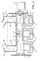
- a bed pan and urine bottle washing end disinfecting machine generally indicated at 1 comprises a cabinet 2 with a door 3 pivotally mounted on a front wall of the cabinet 2 for movement about a vertical axis 4 between a closed position and the open position shown. With the door in the open position shown, access is obtained through an opening 5 to the interior of a washing chamber 6 of the machine, the washing chamber 6 having, as shown in Figures 7 to 9, an upper part which is generally rectangular in horizontal section and a lower part which tapers downwardly to an outlet pipe 7 with a water trap 8 therein and connected to a waste discharge pipe 9.
- the cabinet 2, the door 3 and the washing chamber 6 are formed of a chemically resistant fibreglass or glass reinforced plastics material, which material is both cheaper and lighter than the conventionally used stainless steel and also requires less maintenance to keep it in a presentable condition.
- a transverse shaft 10 rotatably mounted in opposite side walls 6a, 6b of the chamber 6 by means of bearings 11 and 12 and rotatable by means of an electric motor 13.
- the shaft 10 has a square section but it could be of circular or other desired section.
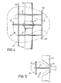
- an upper part 16 of a cradle comprising, as shown in Figures 2, 3 and 4, a central rearwardly extending member 16, a large generally U-shaped member 17 at the front end, a smaller generally U-shaped member 18 at the rear end and two bars 19 coupling the U-shaped members 17 and 18 together.
- Each U-shaped member 17, 18 has the free upper ends 17a, 18a of its side arms 17b, 18b turned inwardly and is of a size such that a bed pan.20 of standard size inserted thereinto as shown in Figure 4, will have its forward end projecting beyond the smaller U-shaped member 18, its rear end projecting rearwardly beyond the U-shaped member 17 and its side walls in contact with the upstanding side arms 17b, 18b of the U-shaped members 17 and 18 such that it rests in the upper part 15 of the cradle in an approximately horizontal orientation as shown in Figure 3:
- the cradle 15 is formed as a plurality of urine bottle holders 21.
- Figure 2 shows that there arc three of these in the illustrated embodiment, each comprising a generally rectangular collar 22 with its upper side secured to the shaft 10, for example by welding, an angled stem 23 projecting from the lower side of the collar 22 and a generally U-shaped member 24 having a middle portion secured to the stem 23 and upwardly projecting side portions.
- the cradle 15 also includes, above the urine bottle holders 21, a single rail 25 projecting substantially the full width of the chamber 6 and secured to the shaft 10.
- a respective urine bottle 26 can be placed in each holder 21, so that a neck 27 of the bottle projects through the collar 22 and a body 28 of the bottle is supported on the cross piece of the U-shaped member 24 and is located by the upwardly extending side arms thereof in substantially the orientation of use, that is to say an orientation in which the contents of the bottle are not likely to be spilled.
- the shaft 10 can be rotated in a clockwise direction as viewed in Figure 3 through an angle of 110 0 , thereby moving the cradle 15 to the position shown in Figure 6.
- the contents of the bed pan 20 and urine bottles 26 will fall under the force of gravity into the outlet pipe 7 of the chamber 6.
- a water inlet 29 is provided in a top wall 30 of the chamber 6 and is controlled by a solenoid valve which is opened when the shaft 10 has rotated 45 from the initial position, as shown in Figure 8, thereby to form a waterfall 31, as shown in Figures 8 and 9.
- a water inlet 32 in a rear wall 6c of the chamber 6 is opened to form a curtain of water 33 on a wall portion 34 at the rear lower part of the chamber 6.
- the combined effects of the water inlets 29 and 32 which are supplied from a header tank 2a located within an upper part of the cabinet 2, is to provide a considerable downward flow of water, for example of the order of two gallons in the space of two to three seconds, such that solids will be forceably flushed from the bed pan 20 and through the water trap 8 and so that the trap 8 will not become clogged by toilet paper or a paper cover used to cover the bed pan 20 while carrying it to the machine.
- the shaft 10 continues to rotate from the position of Figure 8 to rotate the bed pan 20 and urine bottles 26 to the orientation of Figure 6, that is to say 110 o from the initial loading position, and in the orientation of Figure 6, the bed pan 20 is washed by a hot water jet emanating from a water inlet 35 in the back wall 6c of the chamber 6 and the urine bottles 26 are washed internally by jets of hot water directed upwardly into the necks 27 thereof from three nozzles 35a mounted in a front wall of the chamber 6 to ensure that they are throughly cleansed.
- the three hot water nozzles 35a are fed by a water pump 36b driven by an electric motor.
- a steam generator 2b then supplies a steam nozzle 35c to effect a steam disinfection cycle.
- the steam cycle is initiated by a cam controller, which cam controller also controls the energisation of the motor 13 to rotate the cradle 15 following closing of the door, the opening of the solenoid valve to feed the cold water flushes from the water inlets 29 and 32 and the hot water jets from the nozzles 35a supplied by the water pump 35b.
- a cam controller which cam controller also controls the energisation of the motor 13 to rotate the cradle 15 following closing of the door, the opening of the solenoid valve to feed the cold water flushes from the water inlets 29 and 32 and the hot water jets from the nozzles 35a supplied by the water pump 35b.
- the door 3 is opened and closed by a reversible electric drive motor which can, for example, apply a force to an angled arm rigid with the door and projecting within the cabinet 2.
- the cabinet of the machine may therefore be provided with a pressure pad 36 on which the operator can place a foot to apply pressure after the bed pan and urine bottle have been inserted into the machine washing chamber 6 through the access opening 5.
- the door 3 will then close and the washing cycle will either be automatically initiated or if preferred can be separately initiated by the operator again applying pressure to the pressure pad 36.
- the door 3 as shown in Figures 10 and 11, has an outer larger portion 3a and an inner smaller portion 3b, which smaller portion 3b in a closed position of the door 3 projects inwardly into the access opening 5 of the chamber 6.
- a peripheral seal 37 is provided on the outer portion 3a adjacent its junction with the inner portion 3b, the seal 37 pressing against the adjacent face 2c of the cabinet 2 in the closed position of the door. It will be seen from Figure 11 that a lower front wall portion 38 of the chamber 6 extends downwardly from the upper edge of the portion 2c.
- the outer part 3a of the door has a trough 39 at its inner lower edge which trough 39 will collect condensate water running downwardly on the inside face of the portion 3h of the door and the seal 37 when the door is in an open position.
- a flexible hose 40 provides a drain from the trough 39 to an outlet 41 in the wall portion 38 with a water trap 42 in the hose 40 and with a flexible flap 43 covering the outlet 41 so that liquids and gases from within the washing chamber'6 cannot pass back upwardly through the hose 40.
- the inner portion 3b of the door has a curved lower edge 44 to assist run-off of condensation from the inside of the door onto the vertical face of the adjacent seal 37 and into the trough 39.
- the hose 40 is secured to the door 3 adjacent the pivot axis 4 of the door to minimise movement of the hose during opening and closing movements of the door.
- a light preferably a flashing light, is illuminated on an indication panel 45a of the cabinet 2 to indicate that the machine has malfunctioned and that a service engineer should be called.
- the door is not opened at the end of the cycle so that bed pans and urine bottles within the machine which have been washed but not disinfected cannot inadvertently be removed from the machine and re-used with the possibility thereby of cross- infecting other patients, until the fault in the steam cycle has been corrected by the service engineer and the machine recylced to disinfect the bed pan and urine bottles.
- the cradle 15 can receive, as an alternative to the bed pan 20 and three urine bottles 26 shown in Figure 2, various other ward utensils, such as vomit bowls and kidney dishes.
- various other ward utensils such as vomit bowls and kidney dishes.
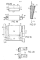
- a bed pan and urine bottle washing and disinfecting machine 50 has a cabinet 52 with an access opening 53 therein leading to a washing and disinfecting chamber which can substantially correspond to the chamber 6 of the machine 1 of the embodiment of Figures 1 to 11.
- the machine 50 of Figures 12 to 20 has a vertically sliding door 54 to close the access opening 53.
- the door 54 is raised to an open position and lowered to a closed position in which it obstructs the access opening 53 but it will be appreciated that an alternative embodiment is equally possible, that is to say where the door is lowered to a position below the opening 53 to allow access to the opening and is raised to its closed position.
- the door 54 as can b 3 seen from Figures 13, 14 and 17, is wedge shaped with a greater thickness at the upper edge than at the lower edge.
- a first end of each of a pair of toothed drive belts 55, 56 are attached to the upper edge of the door 54 and the belts pass over upper pulleys 57, 58 and around lower, idler pulleys 59, 60 and have their other ends attached to the lower edge of the door 54.
- the pulleys 57, 58 are rigidly secured on.
- a shaft 61 and the shaft 61 can be driven by way of a worm and wheel drive 62 by an electric motor 63.
- the idler pulleys 59, 60 can also be toothed pulleys and can be securely mounted on a shaft 64 or rotatable en the shaft 64.
- the door By rotating the motor 63, the door can be raised or lowered.
- the door 54 has a projecting flange 65 which cooperates with a respective guide rail 66 (only one of which is shown in Figure 12) by engaging in a groove 67 thereof, the guide rails 66 being bolted to angle members 68 of a machine frame which also mounts the washing chamber and panels to form the cabinet 52, by bolts which pass through elongate apertures 69, Figure 20, whereby the guide rails 66 are adjustable in position towards and away from the front face of the cabinet 52.
- the adjacent portion of the wall of the washing chamber of the machine projects outwardly to form a face 70, with which face 70 a cooperating flexible seal 71 on the door cooperates in the lower, closed position of the door.
- the seal 71 is a peripheral seal, as can be seen from Figure 15, with two lateral side portions 71a which cooperate respectively with the faces 70, a lower portion 71b which cooperates with a sill 72 formed by the wall of the washing chamber at the lower edge of the access opening 53 and an upper portion 71c which cooperates with a face 73 of the wall of the washing chamber at the upper edge of the access opening 53.
- Figure 12 shows the machine in its normal position of rest with the door 54 in a raised position so that used bed pans and urine bottles can be inserted through the access opening 53 and located on th6 cradle which is provided within the washing chamber as described with reference to Figures 1 to 11 but not shown in Figures 12 to 20.
- the electric motor 63 can then be energised to drive the worm drive 62 and rotate the shaft 61 and the.pull p ys 57, 58 to pull the door 54 into the lowered closed position.
- the guide rails 66 are so adjusted on installation of the machine that as the lower portion 71b of the seal 71 moves into abutment with the sill 72, the side portions 71a.
- the motor 63 is then de-energised while the machine effects its washing and disinfection cycle. At the end of the washing and disinfecting cycle, the electric motor 63 is energised for rotation in an opposite direction to raise the door to the open position of Figure 12 and allow the washed and disinfected bed pans and urine bottles to be removed.
- a sliding door 54 as described can have the advantages that opening and closing of the door requires no manual effort on behalf of the operator, operation can be substantially silent, the seal 71 can have a long life since it is not subjected to large impact forces such as those which arise when a pivoted door is banged closed and the door projects only a very small distance from the front of the machine in both the open and the closed position whereby the machine of Figures 12 to 20 can be housed in a relatively small space.
- the door 5' is hollow and filled with high-density heat resistant foam or similar insulating material which prevents the outer surface of the door from becoming hot through conducted heat from the washing chamber.
Landscapes
- Health & Medical Sciences (AREA)
- Epidemiology (AREA)
- Life Sciences & Earth Sciences (AREA)
- Animal Behavior & Ethology (AREA)
- General Health & Medical Sciences (AREA)
- Public Health (AREA)
- Veterinary Medicine (AREA)
- Accommodation For Nursing Or Treatment Tables (AREA)
- Apparatus For Disinfection Or Sterilisation (AREA)
Priority Applications (1)
| Application Number | Priority Date | Filing Date | Title |
|---|---|---|---|
| AT81306122T ATE15441T1 (de) | 1981-01-02 | 1981-12-23 | Reinigungs- und desinfizierungsvorrichtung fuer stechbecken und urinflaschen. |
Applications Claiming Priority (4)
| Application Number | Priority Date | Filing Date | Title |
|---|---|---|---|
| GB8100015 | 1981-01-02 | ||
| GB8100015 | 1981-01-02 | ||
| GB8125060 | 1981-08-17 | ||
| GB8125060 | 1981-08-17 |
Publications (2)
| Publication Number | Publication Date |
|---|---|
| EP0055926A1 true EP0055926A1 (de) | 1982-07-14 |
| EP0055926B1 EP0055926B1 (de) | 1985-09-11 |
Family
ID=26278015
Family Applications (1)
| Application Number | Title | Priority Date | Filing Date |
|---|---|---|---|
| EP81306122A Expired EP0055926B1 (de) | 1981-01-02 | 1981-12-23 | Reinigungs- und Desinfizierungsvorrichtung für Stechbecken und Urinflaschen |
Country Status (4)
| Country | Link |
|---|---|
| US (1) | US4527843A (de) |
| EP (1) | EP0055926B1 (de) |
| DE (1) | DE3172278D1 (de) |
| GB (1) | GB2090523B (de) |
Cited By (3)
| Publication number | Priority date | Publication date | Assignee | Title |
|---|---|---|---|---|
| EP0093846A1 (de) * | 1982-03-15 | 1983-11-16 | S I C Ag | Verfahren zur automatischen Entleerung und Reinigung von Hygienegefässen und Vorrichtung zu seiner Durchführung |
| FR2725135A1 (fr) * | 1994-09-29 | 1996-04-05 | Hygenor | Procede et dispositif pour laver et desinfecter un recipient hygienique par projection d'eau sous pression |
| FR2757765A1 (fr) * | 1996-12-31 | 1998-07-03 | Sofinor | Machine de lavage pour ustensiles du genre bassin ou autre recipient pour collectivites, notamment en milieu hospitalier |
Families Citing this family (10)
| Publication number | Priority date | Publication date | Assignee | Title |
|---|---|---|---|---|
| GB2176100B (en) * | 1985-06-03 | 1988-06-08 | Scott Western Ltd | Bed-pan washing machine |
| GB2247624B (en) * | 1990-09-06 | 1994-04-20 | Cannon Rubber Ltd | Sterilising method and apparatus for use therein |
| DE19522525A1 (de) * | 1994-10-04 | 1996-04-11 | Kunze Concewitz Horst Dipl Phy | Verfahren und Vorrichtung zum Feinstreinigen von Oberflächen |
| US7556767B2 (en) * | 1997-12-17 | 2009-07-07 | Ethicon, Inc. | Integrated washing and sterilization process |
| US20050163655A1 (en) * | 1997-06-11 | 2005-07-28 | Szu-Min Lin | Integrated washing and sterilization process |
| US9022047B2 (en) * | 2007-01-26 | 2015-05-05 | Unified Brands, Inc. | Rotisserie skewer, basket and parts cleaning assembly |
| EP2425862B1 (de) * | 2010-09-07 | 2012-08-29 | Miele & Cie. KG | Verfahren zur Reinigung und thermischen Desinfektion von Spülgut |
| DK2755695T3 (en) * | 2011-09-14 | 2017-07-31 | Meiko Maschinenbau Gmbh & Co | CLEANING AND DISINFECTING APPARATUS FOR TREATING CONTAINERS FOR HUMAN EXCRETIONS |
| US9561296B1 (en) | 2015-08-11 | 2017-02-07 | Shawki Sobhy | Disinfecting apparatus for restraining devices |
| US10821042B1 (en) * | 2018-03-27 | 2020-11-03 | Beatrice Williams | Patient bed with mattress and integrated bed pan |
Citations (5)
| Publication number | Priority date | Publication date | Assignee | Title |
|---|---|---|---|---|
| US1661221A (en) * | 1926-12-15 | 1928-03-06 | George F Hall | Bedpan washer |
| GB1283049A (en) * | 1968-10-07 | 1972-07-26 | Castan Ltd | Apparatus for emptying and cleaning bed pans |
| US4015614A (en) * | 1974-01-29 | 1977-04-05 | Aktiebolaget Electrolux | Apparatus for washing sanitary conveniences such as bed pans and the like |
| CH602202A5 (en) * | 1976-01-20 | 1978-07-31 | Sic Ag | Rinsing and disinfecting installation for hospital |
| DE8122304U1 (de) * | 1980-08-19 | 1981-12-03 | SIC AG, 4020 Basel | "Vorrichtung zum Spülen und Desinfizieren" |
Family Cites Families (12)
| Publication number | Priority date | Publication date | Assignee | Title |
|---|---|---|---|---|
| US620006A (en) * | 1899-02-21 | Shutter-operating device | ||
| US1687147A (en) * | 1921-12-27 | 1928-10-09 | Emerson D Sawyer | Barrier device for stopping vehicles |
| US1652186A (en) * | 1922-08-12 | 1927-12-13 | Joseph B Strauss | Yielding barrier for vehicles |
| US1549203A (en) * | 1924-11-12 | 1925-08-11 | Howland H Mcclure | Railway gate |
| US1888612A (en) * | 1931-09-21 | 1932-11-22 | David P Anderson | Lifting mechanism |
| US1916579A (en) * | 1932-03-05 | 1933-07-04 | James G Hopkins | Electrically operated window |
| US2270484A (en) * | 1940-02-19 | 1942-01-20 | Chicago Flexible Shaft Co | Self-sealing door for furnaces |
| US2843375A (en) * | 1955-11-16 | 1958-07-15 | Richards Wilcox Mfg Co | Combined sliding and side sealing door |
| DE1285357B (de) * | 1963-11-27 | 1968-12-12 | Porsche Kg | Stellvorrichtung fuer lotrecht schiebbare Fenster |
| US3214801A (en) * | 1964-10-22 | 1965-11-02 | Nachtsheim Peter | Hinged double-hung windows |
| DE1584250A1 (de) * | 1965-07-01 | 1970-03-05 | Konrad Ziesling | Druckluftmotorantrieb fuer Schiebehubtuer,Schiebehubfenster usw.,insbesondere fuer Kapellen |
| US3714737A (en) * | 1971-02-08 | 1973-02-06 | Hoplab Inc | Operating mechanism for vertically sliding door |
-
1981
- 1981-12-23 EP EP81306122A patent/EP0055926B1/de not_active Expired
- 1981-12-23 US US06/333,891 patent/US4527843A/en not_active Expired - Fee Related
- 1981-12-23 DE DE8181306122T patent/DE3172278D1/de not_active Expired
- 1981-12-23 GB GB8138801A patent/GB2090523B/en not_active Expired
Patent Citations (5)
| Publication number | Priority date | Publication date | Assignee | Title |
|---|---|---|---|---|
| US1661221A (en) * | 1926-12-15 | 1928-03-06 | George F Hall | Bedpan washer |
| GB1283049A (en) * | 1968-10-07 | 1972-07-26 | Castan Ltd | Apparatus for emptying and cleaning bed pans |
| US4015614A (en) * | 1974-01-29 | 1977-04-05 | Aktiebolaget Electrolux | Apparatus for washing sanitary conveniences such as bed pans and the like |
| CH602202A5 (en) * | 1976-01-20 | 1978-07-31 | Sic Ag | Rinsing and disinfecting installation for hospital |
| DE8122304U1 (de) * | 1980-08-19 | 1981-12-03 | SIC AG, 4020 Basel | "Vorrichtung zum Spülen und Desinfizieren" |
Cited By (3)
| Publication number | Priority date | Publication date | Assignee | Title |
|---|---|---|---|---|
| EP0093846A1 (de) * | 1982-03-15 | 1983-11-16 | S I C Ag | Verfahren zur automatischen Entleerung und Reinigung von Hygienegefässen und Vorrichtung zu seiner Durchführung |
| FR2725135A1 (fr) * | 1994-09-29 | 1996-04-05 | Hygenor | Procede et dispositif pour laver et desinfecter un recipient hygienique par projection d'eau sous pression |
| FR2757765A1 (fr) * | 1996-12-31 | 1998-07-03 | Sofinor | Machine de lavage pour ustensiles du genre bassin ou autre recipient pour collectivites, notamment en milieu hospitalier |
Also Published As
| Publication number | Publication date |
|---|---|
| EP0055926B1 (de) | 1985-09-11 |
| DE3172278D1 (en) | 1985-10-17 |
| GB2090523A (en) | 1982-07-14 |
| US4527843A (en) | 1985-07-09 |
| GB2090523B (en) | 1985-02-06 |
Similar Documents
| Publication | Publication Date | Title |
|---|---|---|
| US4527843A (en) | Bed pan and urine bottle washing and disinfecting machines | |
| US5960483A (en) | Lavatory having a swivelling bowl | |
| US4805649A (en) | Beverage glass washer | |
| US3886936A (en) | Hydrotherapy unit | |
| EP0873742B1 (de) | Vorrichtung zum Waschen des menschlichen Körpers | |
| CN111281807A (zh) | 一种肿瘤内科化疗装置 | |
| EP0691819B1 (de) | Vorrichtung zum automatischen reinigen und vorbereiten auf wiederverwendung von toiletten | |
| EP0047408B1 (de) | Verfahren zum Entleeren, Reinigen, Desinfektion von Hygiene-Gefässen im Pflegesektor ohne Kontaminierung der äusseren Vorrichtung zu seiner Durchführung | |
| EP0093846A1 (de) | Verfahren zur automatischen Entleerung und Reinigung von Hygienegefässen und Vorrichtung zu seiner Durchführung | |
| KR200343449Y1 (ko) | 환자용 침대 | |
| US4974268A (en) | Chair bathtub | |
| US5875800A (en) | Device for cleaning utensils and removable chamber into which the utensils are disposed | |
| EP0950771B1 (de) | Automatische öffentliche Toilette | |
| US4670061A (en) | Process for improving the automatic emptying and cleaning of hygienic vessels under optimum infeed of rinsing water at minimal water usage and arrangement for implementing the process | |
| WO2022171921A1 (es) | Maquina exprimidora con sistema y procedimiento de higienizacion | |
| NL8603085A (nl) | Inrichting voor het reinigen en desinfecteren van een langgerekt medisch apparaat. | |
| JP2010069188A (ja) | 飲料供給装置 | |
| US20050055758A1 (en) | Chemical toilet with pumpable storage tank | |
| US2080745A (en) | Cleansing device | |
| US5240686A (en) | Arrangement for emptying and cleaning hygienic vessels | |
| EP0023196A1 (de) | Verfahren zum Desinfizieren von Gegenständen zum persönlichen Gebrauch von Patienten und Vorrichtung dafür in einem Spülsterilisator | |
| EP1354577B1 (de) | Wasch- und Desinfektionsmaschine mit einer automatischen Drehvorrichtung für einen Halter für sanitäre Einrichtungen | |
| US1807634A (en) | Bedpan washer | |
| FR2725135A1 (fr) | Procede et dispositif pour laver et desinfecter un recipient hygienique par projection d'eau sous pression | |
| DE8122304U1 (de) | "Vorrichtung zum Spülen und Desinfizieren" |
Legal Events
| Date | Code | Title | Description |
|---|---|---|---|
| PUAI | Public reference made under article 153(3) epc to a published international application that has entered the european phase |
Free format text: ORIGINAL CODE: 0009012 |
|
| AK | Designated contracting states |
Designated state(s): AT BE CH DE FR IT LU NL SE |
|
| 17P | Request for examination filed |
Effective date: 19830106 |
|
| ITF | It: translation for a ep patent filed | ||
| RAP1 | Party data changed (applicant data changed or rights of an application transferred) |
Owner name: HUSNIK, FRANZ |
|
| RAP1 | Party data changed (applicant data changed or rights of an application transferred) |
Owner name: AVON MURDOCH LIMITED |
|
| GRAA | (expected) grant |
Free format text: ORIGINAL CODE: 0009210 |
|
| AK | Designated contracting states |
Designated state(s): AT BE CH DE FR IT LI LU NL SE |
|
| PG25 | Lapsed in a contracting state [announced via postgrant information from national office to epo] |
Ref country code: NL Effective date: 19850911 Ref country code: LI Effective date: 19850911 Ref country code: FR Free format text: THE PATENT HAS BEEN ANNULLED BY A DECISION OF A NATIONAL AUTHORITY Effective date: 19850911 Ref country code: CH Effective date: 19850911 Ref country code: BE Effective date: 19850911 Ref country code: AT Effective date: 19850911 |
|
| REF | Corresponds to: |
Ref document number: 15441 Country of ref document: AT Date of ref document: 19850915 Kind code of ref document: T |
|
| PG25 | Lapsed in a contracting state [announced via postgrant information from national office to epo] |
Ref country code: SE Effective date: 19850930 |
|
| REF | Corresponds to: |
Ref document number: 3172278 Country of ref document: DE Date of ref document: 19851017 |
|
| PG25 | Lapsed in a contracting state [announced via postgrant information from national office to epo] |
Ref country code: LU Free format text: LAPSE BECAUSE OF NON-PAYMENT OF DUE FEES Effective date: 19851231 |
|
| REG | Reference to a national code |
Ref country code: CH Ref legal event code: PL |
|
| NLV1 | Nl: lapsed or annulled due to failure to fulfill the requirements of art. 29p and 29m of the patents act | ||
| PLBE | No opposition filed within time limit |
Free format text: ORIGINAL CODE: 0009261 |
|
| STAA | Information on the status of an ep patent application or granted ep patent |
Free format text: STATUS: NO OPPOSITION FILED WITHIN TIME LIMIT |
|
| EN | Fr: translation not filed | ||
| 26N | No opposition filed | ||
| PG25 | Lapsed in a contracting state [announced via postgrant information from national office to epo] |
Ref country code: DE Effective date: 19890901 |