EP0055995B1 - Disposition de circuit d'allumage et fonctionnement d'une lampe de décharge à basse pression à partir d'une source de courant continu - Google Patents
Disposition de circuit d'allumage et fonctionnement d'une lampe de décharge à basse pression à partir d'une source de courant continu Download PDFInfo
- Publication number
- EP0055995B1 EP0055995B1 EP82200006A EP82200006A EP0055995B1 EP 0055995 B1 EP0055995 B1 EP 0055995B1 EP 82200006 A EP82200006 A EP 82200006A EP 82200006 A EP82200006 A EP 82200006A EP 0055995 B1 EP0055995 B1 EP 0055995B1
- Authority
- EP
- European Patent Office
- Prior art keywords
- voltage
- electrode
- lamp
- circuit arrangement
- switching element
- Prior art date
- Legal status (The legal status is an assumption and is not a legal conclusion. Google has not performed a legal analysis and makes no representation as to the accuracy of the status listed.)
- Expired
Links
Images
Classifications
-
- H—ELECTRICITY
- H05—ELECTRIC TECHNIQUES NOT OTHERWISE PROVIDED FOR
- H05B—ELECTRIC HEATING; ELECTRIC LIGHT SOURCES NOT OTHERWISE PROVIDED FOR; CIRCUIT ARRANGEMENTS FOR ELECTRIC LIGHT SOURCES, IN GENERAL
- H05B41/00—Circuit arrangements or apparatus for igniting or operating discharge lamps
- H05B41/02—Details
- H05B41/04—Starting switches
- H05B41/042—Starting switches using semiconductor devices
- H05B41/044—Starting switches using semiconductor devices for lamp provided with pre-heating electrodes
- H05B41/046—Starting switches using semiconductor devices for lamp provided with pre-heating electrodes using controlled semiconductor devices
-
- H—ELECTRICITY
- H05—ELECTRIC TECHNIQUES NOT OTHERWISE PROVIDED FOR
- H05B—ELECTRIC HEATING; ELECTRIC LIGHT SOURCES NOT OTHERWISE PROVIDED FOR; CIRCUIT ARRANGEMENTS FOR ELECTRIC LIGHT SOURCES, IN GENERAL
- H05B41/00—Circuit arrangements or apparatus for igniting or operating discharge lamps
- H05B41/14—Circuit arrangements
- H05B41/16—Circuit arrangements in which the lamp is fed by DC or by low-frequency AC, e.g. by 50 cycles/sec AC, or with network frequencies
- H05B41/18—Circuit arrangements in which the lamp is fed by DC or by low-frequency AC, e.g. by 50 cycles/sec AC, or with network frequencies having a starting switch
Definitions
- the invention relates to a circuit arrangement for igniting and operating a low-pressure discharge lamp, provided with two electrodes, at least one of which can be preheated, from a direct current source, in which an electronic switching element lying parallel to the lamp and in series with the preheatable electrode (cathode) is reached after reaching it the ignition temperature of the preheated electrode is switched to its non-conductive state, whereby the heating circuit is interrupted and the full DC voltage is applied to the lamp.
- Such a circuit arrangement is known from US-PS 3720861.
- This circuit arrangement works with pure direct current and uses a bipolar transistor, which is controlled by a thyristor, to switch the heating circuit of the lamp.
- a bipolar transistor which is controlled by a thyristor, to switch the heating circuit of the lamp.
- a thyristor When operating with pure direct current, however, only a single attempt to start is possible. If the lamp does not ignite, the thyristor remains conductive and a new attempt can only be made after the voltage has been switched off and on again.
- this circuit arrangement is dependent on the use of a high-voltage transistor designed for the ignition voltage of the lamp. However, these have only a small current gain, so that a resistor in series with the control thyristor must be correspondingly small.
- the peak voltage storage consisting of a diode and a charging capacitor, is provided at the input of the Schmitt trigger.
- a preferred embodiment of the circuit arrangement according to the invention is characterized in that the control electrode of the electronic switching element is connected via a voltage divider both to the anode of the discharge lamp and to the output of the Schmitt trigger, which is dependent on the voltage from the voltage drop across the preheated electrode is controlled via a voltage divider which is parallel to the charging capacitor and consists of a zener diode and a resistor.
- the preferred circuit arrangement manages with a relatively small charging capacitor if, according to a development according to the invention, the voltage divider connected to the control electrode of the electronic switching element has a field-effect transistor on the side of the Schmitt trigger, which is caused by the voltage at the output of the Schmitt trigger is controlled.
- the voltage divider connected to the control electrode of the electronic switching element has a zener diode on the lamp anode side.
- Schmitt triggers that are coupled back through a resistor are provided.
- This embodiment is advantageous if individual commercially available Schmitt triggers have too low a hysteresis, as a result of which the difference in control voltages between the break points became too small for the application in question.
- Operation with pulsating direct current has the advantage that a thyristor can be used as the electronic switching element.
- a high-voltage field-effect transistor can be used as a switching element.
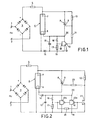
- ballast 5 consists of an ohmic resistor, but preferably of an electronic switched-mode power supply, as is e.g. in U.S. Patent 3,890,537.
- the discharge lamp has a preheatable electrode 6 (cathode) and a non-preheatable counter electrode 7 (anode).
- a thyristor 8 Parallel to the lamp 4 and in series with the lamp cathode 6 is a thyristor 8, the control electrode 9 of which is connected via a voltage divider consisting of two resistors 10 and 11 both to the anode 7 of the discharge lamp 4 and to the output 12 of a Schmitt trigger 13 .
- the Schmitt trigger 13 draws its supply voltage via a peak voltage memory arranged in parallel with the lamp cathode 6, consisting of the series connection of a diode 14 and a charging capacitor 15, from the voltage drop across the preheated cathode 6.
- the Schmitt trigger 13 is of the same voltage via a parallel to the charging capacitor 15, consisting of a Zener diode 16 and a resistor 17, a voltage divider, the center tap of which is connected to the input 18 of the Schmitt trigger 13.
- the low pressure discharge lamp 4 e.g. a 20W fluorescent lamp is supplied with pulsating direct current via the rectifier bridge 3.
- the ballast 5 serves to limit the current. After the mains voltage has been applied, no current initially flows through the lamp cathode 6; the connection points 19 and 20 thus have the same potential.
- the output 12 of the Schmitt trigger 13 is necessarily at the same potential.
- the control electrode 9 of the thyristor 8 therefore receives a positive voltage via the voltage divider 10, 11, so that the thyristor 8 can ignite. After the thyristor 8 has been ignited, a current flows through it through the preheatable cathode 6 and is limited only by the ballast 5.
- the lamp current flows over the cathode 6 and causes a voltage drop between points 19 and 20; this is sufficient to keep the Schmitt trigger 13 in its stable state. Only when the voltage between points 19 and 20 is very low, which is only below when the lamp 4 is not ignited or when it is switched off, does the Schmitt trigger 13 flip back to its original state and enables the thyristor 8 and thus one to be fired again try to start lamp 4 again (in practice after about 0.1 sec).
- the circuit arrangement according to FIG. 1 is constructed similarly to that according to FIG. 1 and essentially works in the same way. Since commercially available Schmitt triggers (eg Valvo HEF 4093) often only have a low hysteresis, ie that the difference between the control voltages between the tipping points is relatively small, two are negative-coupled in the circuit arrangement according to FIG. 2 by a resistor 21 Schmitt triggers 13a and 13b are provided.
- Schmitt triggers eg Valvo HEF 4093
- the charging capacitor 15 in the arrangement according to FIG. 1 must be relatively large so that it is not discharged too quickly by the control current of the thyristor 8. This would lead to undesired re-ignition of the thyristor 8 after the preheating has ended before the lamp 4 itself has ignited.
- the arrangement according to FIG. 2 manages with a much smaller charging capacitor 15 if the resistor 11 is replaced by a field effect transistor 22 (n-channel enhancement MOSFET) and the diode 14 is moved to the positive end of the lamp cathode 6.
- the field effect transistor 22 is controlled by the voltage at the output 12 of the Schmitt triggers 13a and 13b.
- control electrode 9 of the thyristor 8 is connected in a low-resistance manner via a limiting resistor 23 and the field-effect transistor 22 directly to the negative side of the rectifier bridge 3 after the preheating has ended, without the charging capacitor 15 having to supply the control current which may still be flowing for the thyristor 8.
- the resistor 10 of the voltage connected to the control electrode 9 of the thyristor 8 divider 10, 11 or 10, 22 can be replaced by a Zener diode, the Zener voltage is slightly higher than the operating voltage of the lamp 4. This provides additional security against undesired re-ignition of the thyristor 8, since after ignition of the lamp 4 no positive Voltage can reach the control electrode 9 of the thyristor 8.
Landscapes
- Circuit Arrangements For Discharge Lamps (AREA)
Claims (6)
Applications Claiming Priority (2)
| Application Number | Priority Date | Filing Date | Title |
|---|---|---|---|
| DE19813100177 DE3100177A1 (de) | 1981-01-07 | 1981-01-07 | Schaltungsanordnung zum zuenden und betrieb einer niederdruckentladungslampe aus einer gleichstromquelle |
| DE3100177 | 1981-01-07 |
Publications (2)
| Publication Number | Publication Date |
|---|---|
| EP0055995A1 EP0055995A1 (fr) | 1982-07-14 |
| EP0055995B1 true EP0055995B1 (fr) | 1985-05-02 |
Family
ID=6122245
Family Applications (1)
| Application Number | Title | Priority Date | Filing Date |
|---|---|---|---|
| EP82200006A Expired EP0055995B1 (fr) | 1981-01-07 | 1982-01-05 | Disposition de circuit d'allumage et fonctionnement d'une lampe de décharge à basse pression à partir d'une source de courant continu |
Country Status (3)
| Country | Link |
|---|---|
| EP (1) | EP0055995B1 (fr) |
| JP (1) | JPS57136799A (fr) |
| DE (2) | DE3100177A1 (fr) |
Families Citing this family (6)
| Publication number | Priority date | Publication date | Assignee | Title |
|---|---|---|---|---|
| JPS59211995A (ja) * | 1983-05-14 | 1984-11-30 | 松下電工株式会社 | 高圧放電灯点灯装置 |
| HU190862B (en) * | 1983-11-23 | 1986-11-28 | Tungsram Rt,Hu | High-pressure discharge lamp with favourable colour reproduction |
| GB2153606A (en) * | 1984-01-26 | 1985-08-21 | Rodney Cairn Hope | Output current controller for fluorescent lamp ballast |
| DK339586D0 (da) * | 1986-07-16 | 1986-07-16 | Silver Gruppen Prod As | Elektronisk ballast |
| DE3641070A1 (de) * | 1986-12-02 | 1988-06-16 | Philips Patentverwaltung | Schaltungsanordnung zum betrieb von hochdruck-gasentladungslampen mittels eines impulsfoermigen versorgungsstromes |
| DE3936809C1 (fr) * | 1989-11-04 | 1991-02-21 | Ruhrkohle Ag, 4300 Essen, De |
Family Cites Families (3)
| Publication number | Priority date | Publication date | Assignee | Title |
|---|---|---|---|---|
| US3611024A (en) * | 1968-07-23 | 1971-10-05 | Matsushita Electric Industrial Co Ltd | Semiconductor apparatus for controlling the brightness of a discharge lamp |
| US3720861A (en) * | 1970-12-21 | 1973-03-13 | Teletype Corp | Fluorescent lamp igniting circuit |
| US3890537A (en) * | 1974-01-02 | 1975-06-17 | Gen Electric | Solid state chopper ballast for gaseous discharge lamps |
-
1981
- 1981-01-07 DE DE19813100177 patent/DE3100177A1/de not_active Withdrawn
-
1982
- 1982-01-04 JP JP57000175A patent/JPS57136799A/ja active Pending
- 1982-01-05 DE DE8282200006T patent/DE3263317D1/de not_active Expired
- 1982-01-05 EP EP82200006A patent/EP0055995B1/fr not_active Expired
Also Published As
| Publication number | Publication date |
|---|---|
| JPS57136799A (en) | 1982-08-23 |
| DE3100177A1 (de) | 1982-08-05 |
| EP0055995A1 (fr) | 1982-07-14 |
| DE3263317D1 (en) | 1985-06-05 |
Similar Documents
| Publication | Publication Date | Title |
|---|---|---|
| DE2816415C2 (fr) | ||
| DE2323011C3 (de) | Schaltungsanordnung zur Zündung und zum Betrieb einer Gasentladungslampe | |
| DE2263582C2 (de) | Anordnung zum Zünden und Betrieb einer Niederdruckquecksilberdampfentladungslampe | |
| DE3231939C2 (fr) | ||
| DE2925691C2 (de) | Schaltungsanordnung zum Zünden und Speisen mindestens einer Gas- und/oder Dampfentladungslampe | |
| DE3781004T2 (de) | Vorrichtung zur begrenzung von stromstoessen. | |
| DE3046617C2 (fr) | ||
| DE2751464A1 (de) | Starter zum zuenden einer gas- und/oder dampfentladungslampe | |
| DE2312652A1 (de) | Anordnung mit einer gas- und/oder dampfentladungslampe | |
| EP0055995B1 (fr) | Disposition de circuit d'allumage et fonctionnement d'une lampe de décharge à basse pression à partir d'une source de courant continu | |
| DE1764995C3 (de) | Schaltungsanordnung zur Zündung und Speisung einer Gas- und/oder Dampfentladungslampe | |
| DE3047289A1 (de) | Zuendvorrichtung fuer eine niederdruckentladungslampe | |
| DE69616451T2 (de) | Umschaltanordnung | |
| EP0003528A1 (fr) | Dispositif électronique de réglage d'intensité lumineuse pour lampe à décharge sans cathode chauffée | |
| DE69518424T2 (de) | Verschlüsselungsschaltung für dimmbare Leuchtstofflampen | |
| DE3022773C2 (fr) | ||
| EP0021508B1 (fr) | Circuit d'allumage et de commande pour lampes à décharge dans un gaz et/ou une vapeur | |
| EP0111956B1 (fr) | Disposition de circuit pour mettre en marche des lampes à décharge à haute pression | |
| EP0564895B1 (fr) | Ballast électronique pour lampes à décharge basse-pression | |
| DE3622984C2 (fr) | ||
| EP0111296B1 (fr) | Dispositif pour contrôler l'intensité d'une lampe de décharge à basse pression | |
| DE69315640T2 (de) | Verzögerungsmittel in einer Anlaufschaltung eines Vorschaltgerätes | |
| EP0015304A1 (fr) | Procédé et dispositif pour charger un condensateur | |
| DE3786501T2 (de) | Schaltung zur Begrenzung von Überspannungen in gleichstrombetriebenen Lampen. | |
| EP2140735B1 (fr) | Ensemble circuit servant à amorcer et à faire fonctionner au moins une lampe à décharge |
Legal Events
| Date | Code | Title | Description |
|---|---|---|---|
| PUAI | Public reference made under article 153(3) epc to a published international application that has entered the european phase |
Free format text: ORIGINAL CODE: 0009012 |
|
| AK | Designated contracting states |
Designated state(s): BE DE FR GB NL |
|
| RAP1 | Party data changed (applicant data changed or rights of an application transferred) |
Owner name: N.V. PHILIPS' GLOEILAMPENFABRIEKEN Owner name: PHILIPS PATENTVERWALTUNG GMBH |
|
| 17P | Request for examination filed |
Effective date: 19820816 |
|
| GRAA | (expected) grant |
Free format text: ORIGINAL CODE: 0009210 |
|
| AK | Designated contracting states |
Designated state(s): BE DE FR GB NL |
|
| REF | Corresponds to: |
Ref document number: 3263317 Country of ref document: DE Date of ref document: 19850605 |
|
| ET | Fr: translation filed | ||
| PLBE | No opposition filed within time limit |
Free format text: ORIGINAL CODE: 0009261 |
|
| STAA | Information on the status of an ep patent application or granted ep patent |
Free format text: STATUS: NO OPPOSITION FILED WITHIN TIME LIMIT |
|
| 26N | No opposition filed | ||
| PGFP | Annual fee paid to national office [announced via postgrant information from national office to epo] |
Ref country code: NL Payment date: 19890131 Year of fee payment: 10 |
|
| PGFP | Annual fee paid to national office [announced via postgrant information from national office to epo] |
Ref country code: DE Payment date: 19900326 Year of fee payment: 9 |
|
| PGFP | Annual fee paid to national office [announced via postgrant information from national office to epo] |
Ref country code: GB Payment date: 19901221 Year of fee payment: 10 |
|
| PGFP | Annual fee paid to national office [announced via postgrant information from national office to epo] |
Ref country code: BE Payment date: 19910104 Year of fee payment: 10 |
|
| PGFP | Annual fee paid to national office [announced via postgrant information from national office to epo] |
Ref country code: FR Payment date: 19910118 Year of fee payment: 10 |
|
| PG25 | Lapsed in a contracting state [announced via postgrant information from national office to epo] |
Ref country code: NL Effective date: 19910801 |
|
| NLV4 | Nl: lapsed or anulled due to non-payment of the annual fee | ||
| PG25 | Lapsed in a contracting state [announced via postgrant information from national office to epo] |
Ref country code: DE Effective date: 19911001 |
|
| PG25 | Lapsed in a contracting state [announced via postgrant information from national office to epo] |
Ref country code: GB Effective date: 19920105 |
|
| PG25 | Lapsed in a contracting state [announced via postgrant information from national office to epo] |
Ref country code: BE Effective date: 19920131 |
|
| BERE | Be: lapsed |
Owner name: N.V. PHILIPS' GLOEILAMPENFABRIEKEN Effective date: 19920131 |
|
| GBPC | Gb: european patent ceased through non-payment of renewal fee | ||
| PG25 | Lapsed in a contracting state [announced via postgrant information from national office to epo] |
Ref country code: FR Effective date: 19920930 |
|
| REG | Reference to a national code |
Ref country code: FR Ref legal event code: ST |