EP0056436A1 - Methods and means for cleaning the interiors of containers, especially beer kegs - Google Patents
Methods and means for cleaning the interiors of containers, especially beer kegs Download PDFInfo
- Publication number
- EP0056436A1 EP0056436A1 EP81108676A EP81108676A EP0056436A1 EP 0056436 A1 EP0056436 A1 EP 0056436A1 EP 81108676 A EP81108676 A EP 81108676A EP 81108676 A EP81108676 A EP 81108676A EP 0056436 A1 EP0056436 A1 EP 0056436A1
- Authority
- EP
- European Patent Office
- Prior art keywords
- barrel
- cleaning
- liquid
- gaseous
- blowing
- Prior art date
- Legal status (The legal status is an assumption and is not a legal conclusion. Google has not performed a legal analysis and makes no representation as to the accuracy of the status listed.)
- Granted
Links
- 238000004140 cleaning Methods 0.000 title claims abstract description 69
- 238000000034 method Methods 0.000 title claims abstract description 36
- 235000013405 beer Nutrition 0.000 title claims abstract description 7
- 239000007788 liquid Substances 0.000 claims abstract description 46
- 238000007664 blowing Methods 0.000 claims abstract description 15
- 230000000903 blocking effect Effects 0.000 claims description 3
- 239000012530 fluid Substances 0.000 abstract description 3
- 230000015572 biosynthetic process Effects 0.000 description 2
- 238000011109 contamination Methods 0.000 description 2
- 238000010586 diagram Methods 0.000 description 2
- 230000000694 effects Effects 0.000 description 2
- 238000005406 washing Methods 0.000 description 2
- XLYOFNOQVPJJNP-UHFFFAOYSA-N water Substances O XLYOFNOQVPJJNP-UHFFFAOYSA-N 0.000 description 2
- 230000004913 activation Effects 0.000 description 1
- 238000005516 engineering process Methods 0.000 description 1
- 239000002360 explosive Substances 0.000 description 1
- 238000011010 flushing procedure Methods 0.000 description 1
- 244000005700 microbiome Species 0.000 description 1
- 238000011112 process operation Methods 0.000 description 1
- 230000035939 shock Effects 0.000 description 1
- 230000001954 sterilising effect Effects 0.000 description 1
- 238000012384 transportation and delivery Methods 0.000 description 1
Images
Classifications
-
- B—PERFORMING OPERATIONS; TRANSPORTING
- B08—CLEANING
- B08B—CLEANING IN GENERAL; PREVENTION OF FOULING IN GENERAL
- B08B9/00—Cleaning hollow articles by methods or apparatus specially adapted thereto
- B08B9/08—Cleaning containers, e.g. tanks
- B08B9/0804—Cleaning containers having tubular shape, e.g. casks, barrels, drums
Definitions
- the invention relates to DE-PS 19 07 416, in which a method and a device for cleaning the inside of beer kegs, namely the so-called KEG kegs, is described.
- the washing process takes place from below via the riser pipe, ie. H. the cleaning liquid exits under pressure through the supply line above the riser pipe and runs gently down the sides of the barrel inner wall after it has been redirected beforehand by the bottom shape of the barrel, the so-called cup, which is designed in terms of flow technology.
- the cleaning liquid falling off on the barrel wall then exits the barrel interior through the pressurized gas paths and reaches the discharge line.
- the amount of cleaning liquid is reduced towards the end of the liquid treatment and the outer pipe surface and the fitting housing projecting into the drum are flooded with a liquid flow.
- a method and a device are also placed under protection in which an improved cleaning of the riser pipe and barrel fitting housing is sought.
- the cleaning liquid is used in an additional operation, which is based on conventional interior cleaning process then, alternately diverted during the cleaning process, such that the liquid on the one hand flows through the riser pipe and on the other hand through the compressed gas valve. After the liquid has escaped from the fitting's compressed gas opening, it inevitably continues to run on the riser pipe, which is intended to flush the outside.
- the invention has for its object to provide a method and a device for cleaning the inside of barrels or the like., In particular of beer barrels of the type mentioned, which enable reliable cleaning of the barrel in a simple manner and in the shortest possible time.
- the method according to the invention provides that a cleaning liquid is introduced into the barrel and is caused to rise in motion by blowing in a gaseous or vaporous medium from below, the barrel being vented to maintain a pressure difference when the gaseous or vaporous medium is blown in . It has proven to be particularly advantageous if the Internal cleaning is carried out in such a way that the liquid level in the barrel is gradually increased from bottom to top and the medium is blown in between these stages.
- a further process step is characterized in that in the case of a barrel with a barrel fitting remaining in the barrel bottom with the connecting piece pointing downward, the cleaning liquid is fed in via the riser pipe and in that the gaseous or vaporous medium is blown in via the compressed gas valve and the feed line for the cleaning liquid as a return air line serves. Furthermore, a liquid can also be used instead of the gaseous or vaporous medium.
- the device for carrying out the method is based on a cleaning head for connection to the drum fitting with through-openings which are connected to liquid and compressed gas supply lines or discharge lines, and is characterized by check valves in the supply lines or discharge lines which are connected via a program circuit can be controlled alternately in such a way that the barrel is filled step by step from bottom to top and the gaseous or vaporous medium is blown in between these filling stages, and by means of a return air line branching off from the supply line for the liquid between the cleaning head and the shut-off valve with a while blowing in of the gaseous or vaporous medium opening further check valve.
- a last feature of the invention is characterized by a valve arranged in the feed line and releasing and blocking the compressed gas supply at short intervals.
- a KEG barrel 1 with a barrel fitting 2 screwed into the barrel bottom is in a position coupled to a cleaning head 3 for its internal cleaning with the head pointing downward.
- the barrel fitting 2 is essentially formed from the fitting housing or cage and from a riser pipe which can be moved in the axial direction and protrudes into the barrel and is designed as an automatically closing valve with through-openings for the cleaning liquid and for the compressed gas. With these openings are at the on couple and actuate the barrel fitting through openings of the cleaning head in a conductive connection and these in turn are connected to a feed line 4 for the cleaning liquid and to a feed line 5 for the compressed gas.
- the cleaning process begins with the entry of cleaning liquid into the barrel via the riser pipe, conveyed from the tank 7 via the pump 8. After reaching a first liquid level shown in FIG. 1, the pump switches off and a shut-off valve 10 closes the feed line 4. The interior of the riser pipe is cleaned at the same time as it is filled.
- Air is blown into the cleaning liquid in the barrel from below by a compressed air source 9 via the feed line 5 and the passage opening for the gas, causing it to start moving and the cleaning process begins.
- the blowing process is ended after a preset period of time by switching off the compressed air source and by blocking the feed line 5 via a shut-off valve 11.
- the return air can escape into the tank 7 via the riser pipe and the feed line 4 and via a return air line 12 branching off between the cleaning head 3 and valve 10 with a shut-off valve 13 .
- An increase in the cleaning effect can also be achieved by intermittent blowing in conjunction with increased pressure of the air into the liquid, which can be carried out, for example, by appropriate activation of the check valve 11.
- pressurized gas instead of the pressurized gas, other pressurized fluid can of course also be used, such as a vaporous medium or a liquid, without leaving the field of the invention.
- the cleaning liquid is forced out of the barrel into line 14 and into tank 7 by redirecting the compressed air via line 16 with shut-off valve 17 and via the riser pipe through the pressure gas valve.
Landscapes
- Engineering & Computer Science (AREA)
- Mechanical Engineering (AREA)
- Cleaning In General (AREA)
- Filling Of Jars Or Cans And Processes For Cleaning And Sealing Jars (AREA)
- Devices For Dispensing Beverages (AREA)
Abstract
Die Erfindung betrifft ein Verfahren zum Innenreinigen von Fässern oder dgl., insbesondere von Bierfässern mit einer im Faßboden verbleibenden Faßarmatur (2) mit einem in das Faß hineinragenden Steigrohr und selbsttätig schließenden Ventilen fu? Durchgangsoffnungen, wobei das Faß über die Faßarmatur an Flüssigkeits- (4) und Druckgas (5)-Zuleitungen bzw. Ableitungen angeschlossen und mit Reinigungsflussigkeit beaufschlagt wird. Dabei wird Reinigungsflüssigkeit unter stufenweiser Erhohung von unten nach oben in das Faß eingegeben und diese durch Einblasen eines gas- oder dampffo?migen Mediums von unten jeweils zwischen den Fullstufen in aufwallende Bewegung versetzt, wodurch das Faß fortschreitend von unten nach oben gereinigt wird. Dabei muß das Faß zum Aufrechterhalten einer Druckdifferenz beim Einblasen des gas- oder damffho ?migen Mediums entluftet werden.The invention relates to a method for cleaning the inside of kegs or the like, in particular beer kegs with a keg fitting (2) remaining in the keg base with a riser pipe projecting into the keg and automatically closing valves for? Through openings, the drum being connected via the drum fitting to liquid (4) and compressed gas (5) feed lines or discharges and to which cleaning fluid is applied. In this process, cleaning liquid is introduced into the barrel from the bottom to the top, gradually increasing the volume by blowing in a gaseous or vaporous medium from below between the full stages, whereby the barrel is cleaned progressively from bottom to top. The barrel must be vented to maintain a pressure difference when blowing in the gaseous or vaporous medium.
Description
Die Erfindung betrifft ein Verfahren und eine Vorrichtung zum Innenreinigen von Fässern oder dgl., insbesondere von Bierfässern mit einer im Faßboden verbleibenden Faßarmatur mit einem in das Faß hineinragenden Steigrohr und selbsttätig schließenden Ventilen für Durchgangsöffnungen, wobei das Faß über die Faßarmatur an Flüssigkeits- und Druckgas-Zuleitungen bzw. -Ableitungen angeschlossen und mit Reinigungsflüssigkeit beaufschlagt wird.The invention relates to a method and a device for cleaning the inside of barrels or the like., In particular beer barrels with a barrel fitting remaining in the barrel bottom with a riser pipe protruding into the barrel and automatically closing valves for through-openings, the barrel via the barrel fitting of liquid and pressure gas -Leadings or -deliveries are connected and cleaning liquid is applied.
Mit diesem Oberbegriff nimmt die Erfindung Bezug auf die DE-PS 19 07 416, in der ein Verfahren sowie eine Vorrichtung zum Innenreinigen von Bierfässern, und zwar die sogenannten KEG-Fässer, beschrieben wird. In einem solchen bekannten vollautomatisch arbeitenden KEG-Reinigungs- und -Füllsystem erfolgt der Waschvorgang von unten über das Steigrohr, d. h. die Reinigungsflüssigkeit tritt durch die Zuleitung oberhalb des Steigrohres unter Druck aus und läuft schwallförmig allseitig an der Faßinnenwand herunter, nachdem sie zuvor durch die strömungstechnisch entsprechend ausgestaltete Bodenform des Fasses, der sogenannten Tasse, umgelenkt wird.With this preamble, the invention relates to DE-PS 19 07 416, in which a method and a device for cleaning the inside of beer kegs, namely the so-called KEG kegs, is described. In such a known fully automatic KEG cleaning and filling system, the washing process takes place from below via the riser pipe, ie. H. the cleaning liquid exits under pressure through the supply line above the riser pipe and runs gently down the sides of the barrel inner wall after it has been redirected beforehand by the bottom shape of the barrel, the so-called cup, which is designed in terms of flow technology.
Die an der Faßwand abfallende Reinigungsflüssigkeit tritt danach durch die Druckgaswege aus dem Faßinneren aus und gelangt in die Ableitung.The cleaning liquid falling off on the barrel wall then exits the barrel interior through the pressurized gas paths and reaches the discharge line.
Der Wirkungsgrad dieses Reinigungsverfahrens ist bekanntlich von zahlreichen Faktoren abhängig, wie z. B. von der Boden- und Wandausbildung des Fasses, vom Abstand des Steigrohres zum Faßboden und insbesondere auch von der Wassermenge sowie vom Wasserdruck, was letztlich dazu führte, daß nicht immer der gewünschte Reinigungs-und Sterilisierungseffekt erreicht wurde.The efficiency of this cleaning process is known to depend on numerous factors, such as. B. from the bottom and wall formation of the barrel, from the distance of the riser to the barrel bottom and in particular also from the amount of water and from the water pressure, which ultimately led to the fact that the desired cleaning and sterilizing effect was not always achieved.
Hinsichtlich einer verbesserten Faßarmaturenreinigung ist in der genannten Patentschrift vorgesehen, daß die Menge der Reinigungsflüssigkeit gegen Ende der Flüssigkeitsbehandlung verringert und dabei die Steigrohraußenflächen und das in das Faß hineinragende Armaturengehäuse mit einem Flüssigkeitsstrom überschwallt wird.With regard to an improved cleaning of the drum fittings, it is provided in the said patent that the amount of cleaning liquid is reduced towards the end of the liquid treatment and the outer pipe surface and the fitting housing projecting into the drum are flooded with a liquid flow.
Es gehört ferner zum Stand der Technik, den Wirkungsgrad der Innenreinigung durch eine sogenannte Intervallreinigung zu erhöhen, dergestalt, daß der durch das Steigrohr einlaufenden Reinigungsflüssigkeit in kurzen Zeitintervallen stoßweise Luft zugeführt wird, wodurch explosionsartige Entladungen auftreten mit dem Ergebnis, daß auf der Behälterwand ringförmige Stoßwellen von oben nach unten entlanglaufen.It is also part of the prior art to increase the efficiency of internal cleaning by means of a so-called interval cleaning, in such a way that the cleaning liquid entering through the riser pipe is intermittently supplied with air in short time intervals, as a result of which explosive discharges occur, with the result that annular shock waves occur on the container wall run from top to bottom.
Diese Intervallspülung hat sich insofern nicht als zufriedenstellend gezeigt, als es keineswegs sichergestellt ist, daß alle Mantelteile mit Reinigungsflüssigkeit beaufschlagt werden, da die Bildung eines durchgehenden Reinigungsfilms als Folge der Unterbrechungen ständig verhindert wird.This interval flushing has not been shown to be satisfactory insofar as it is by no means certain that all jacket parts will be exposed to cleaning fluid, since the formation of a continuous cleaning film as a result of the interruptions is constantly prevented.
In der DE-OS 27 06 590 wird des weiteren ein Verfahren sowie eine Vorrichtung unter Schutz gestellt, bei der eine verbesserte Reinigung von Steigrohr und Faßarmaturengehäuse angestrebt wird. Gemäß dem Verfahren wird hierzu die Reinigungsflüssigkeit in einem zusätzlichen Arbeitsgang, der sich an den herkömmlichen Innenreinigungsvorgang anschließt, während des Reinigungsvorgangs wechselweise umgeleitet, derart, daß die Flüssigkeit einerseits das Steigrohr und andererseits das Druckgasventil durchströmt. Nach Austreten der Flüssigkeit aus der Druckgasöffnung des Fittings läuft diese zwangsläufig auf dem Steigrohr weiter, wodurch eine Umspülung der Außenseite erreicht werden soll.In DE-OS 27 06 590, a method and a device are also placed under protection in which an improved cleaning of the riser pipe and barrel fitting housing is sought. According to the method, the cleaning liquid is used in an additional operation, which is based on conventional interior cleaning process then, alternately diverted during the cleaning process, such that the liquid on the one hand flows through the riser pipe and on the other hand through the compressed gas valve. After the liquid has escaped from the fitting's compressed gas opening, it inevitably continues to run on the riser pipe, which is intended to flush the outside.
Letztlich sei noch auf ein Verfahren zum Innenreinigen von KEG-Fässern hingewiesen, für das in der DE-OS 27 20 320 um Patentschutz nachgesucht wird. Es sieht vor, das Faß mit einer Reinigungsflüssigkeit mit höherer Temperatur und mit entsprechendem Sättigungsdruck zu beaufschlagen mit dem Ziel einer schnelleren und intensiveren Abtötung von Mikroorganismen.Finally, reference should be made to a method for cleaning the inside of KEG barrels, for which patent protection is sought in DE-OS 27 20 320. It provides for the barrel to be charged with a cleaning liquid at a higher temperature and with a corresponding saturation pressure with the aim of killing microorganisms more quickly and intensively.
Allen bekannten Verfahren und Vorrichtungen haftet der Nachteil an, daß die gesamte Mantelfläche einschließlich der Steigrohraußenfläche und auch das Faßarmaturengehäuse nicht sicher von der Reinigungsflüssigkeit erreicht werden, was insbesondere bei stärker verschmutzten Fässern keine befriedigende Innenreinigung sicherstellt.All known methods and devices have the disadvantage that the entire outer surface including the outer tube surface and also the barrel fitting housing are not reliably reached by the cleaning liquid, which does not ensure satisfactory internal cleaning, particularly in the case of heavily soiled barrels.
Der Erfindung liegt die Aufgabe zugrunde, ein Verfahren sowie eine Vorrichtung zum Innenreinigen von Fässern oder dgl., insbesondere von Bierfässern der eingangs genannten Gattung zu schaffen, die auf einfache Art und in kürzester Zeiteinheit eine zuverlässige Reinigung des Fasses ermöglichen.The invention has for its object to provide a method and a device for cleaning the inside of barrels or the like., In particular of beer barrels of the type mentioned, which enable reliable cleaning of the barrel in a simple manner and in the shortest possible time.
Hierzu sieht das Verfahren nach der Erfindung vor, daß eine Reinigungsflüssigkeit in das Faß eingegeben und durch Einblasen eines gas- oder dampfförmigen Mediums von unten in aufwallende Bewegung versetzt wird, wobei das Faß zum Aufrechterhalten einer Druckdifferenz beim Einblasen des gas- oder dampfförmigen Mediums entlüftet wird. Es hat sich als besonders vorteilhaft erwiesen, wenn die Innenreinigung derart ausgeführt wird, daß der Flüssigkeitsstand in dem Faß stufenweise von unten nach oben erhöht wird und das Einblasen des Mediums jeweils zwischen diesen Stufen erfolgt.For this purpose, the method according to the invention provides that a cleaning liquid is introduced into the barrel and is caused to rise in motion by blowing in a gaseous or vaporous medium from below, the barrel being vented to maintain a pressure difference when the gaseous or vaporous medium is blown in . It has proven to be particularly advantageous if the Internal cleaning is carried out in such a way that the liquid level in the barrel is gradually increased from bottom to top and the medium is blown in between these stages.
Alternativ dazu kann das Einblasen des Mediums parallel mit Eingeben der Reinigungsflüssigkeit laufen.Alternatively, the blowing in of the medium can run in parallel with the input of the cleaning liquid.
Eine Steigerung des Reinigungseffektes läßt sich noch insofern erreichen, als das Einblasen des gas- oder dampfförmigen Mediums stoßweise und zusätzlich unter erhöhtem Druck erfolgt.An increase in the cleaning effect can be achieved insofar as the gaseous or vaporous medium is blown in intermittently and additionally under increased pressure.
Ein weiterer Verfahrensschritt zeichnet sich dadurch aus, daß bei einem Faß mit im Faßboden verbleibender Faßarmatur mit nach unten gerichtetem Anschlußstutzen die Reinigungsflüssigkeit über das Steigrohr zugeführt wird und daß das gas- oder dampfförmige Medium über das Druckgasventil eingeblasen und dabei die Zuleitung für die Reinigungsflüssigkeit als Rückluftleitung dient. Ferner kann an Stelle des gas- oder dampfförmigen Mediums auch eine Flüssigkeit Verwendung finden.A further process step is characterized in that in the case of a barrel with a barrel fitting remaining in the barrel bottom with the connecting piece pointing downward, the cleaning liquid is fed in via the riser pipe and in that the gaseous or vaporous medium is blown in via the compressed gas valve and the feed line for the cleaning liquid as a return air line serves. Furthermore, a liquid can also be used instead of the gaseous or vaporous medium.
Die Vorrichtung zur Durchführung des Verfahrens geht aus von einem Reinigungskopf zum Anschluß an die Faßarmatur mit Durchgangsöffnungen, die an Flüssisgkeits- und Druckgas-Zuleitungen bzw. -Ableitungen angeschlossen sind, und ist gekennzeichnet durch Sperrventile in den Zuleitungen bzw. Ableitungen, die über eine Programmschaltung derart wechselweise ansteuerbar sind, daß das Faß stufenweise von unten nach oben gefüllt und zwischen diesen Füllstufen das Einblasen des gas- oder dampfförmigen Mediums erfolgt, und durch eine von der Zuleitung für die Flüssigkeit zwischen dem Reinigungskopf und dem Sperrventil abzweigende Rückluftleitung mit einem während des Einblasens des gas- oder dampfförmigen Mediums öffnenden weiteren Sperrventil.The device for carrying out the method is based on a cleaning head for connection to the drum fitting with through-openings which are connected to liquid and compressed gas supply lines or discharge lines, and is characterized by check valves in the supply lines or discharge lines which are connected via a program circuit can be controlled alternately in such a way that the barrel is filled step by step from bottom to top and the gaseous or vaporous medium is blown in between these filling stages, and by means of a return air line branching off from the supply line for the liquid between the cleaning head and the shut-off valve with a while blowing in of the gaseous or vaporous medium opening further check valve.
Ein letztes Merkmal der Erfindung ist gekennzeichnet durch ein in der Zuleitung angeordnetes, die Druckgaszufuhr in kurzen Intervallen freigebendes und sperrendes Ventil.A last feature of the invention is characterized by a valve arranged in the feed line and releasing and blocking the compressed gas supply at short intervals.
Mit dem Verfahren und der Vorrichtung gemäß der Erfindung wird eine wesentlich verbesserte Innenreinigung von Fässern, insbesondere von Bierfässern aufgezeigt, die absolut sicherstellt, daß durch den von unten nach oben fortschreitenden Reinigungsprozeß kein Teil der Behälterflächen einschließlich der Außenfläche von Steigrohr und Armaturengehäuse ausgelassen wird. Durch beliebige Erhöhung der Anzahl der Verfahrensstufen läßt sich somit selbst bei stärkstem Verschmutzungsgrad eine zuverlässige Reinigung der Fässer als Folge der sehr intensiven Waschvorgänge erreichen.With the method and the device according to the invention, a significantly improved internal cleaning of barrels, in particular beer kegs, is shown, which absolutely ensures that no part of the container surfaces including the outer surface of the riser pipe and fitting housing are left out due to the cleaning process proceeding from the bottom up. By arbitrarily increasing the number of process stages, a reliable cleaning of the drums can be achieved as a result of the very intensive washing processes, even with the heaviest degree of contamination.
Nachfolgend wird ein Ausführungsbeispiel zur Durchführung des Verfahrens gemäß der Erfindung anhand der Figuren näher erläutert. Es zeigen
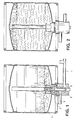
- Fig. 1 u. 2 in Schnittdarstellungen ein mit einem Anschluß- oder Reinigungskopf gekoppeltes Faß in einer ersten und in einer letzten Reinigungsstufe,
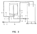
- Fig. 3 ein Schaltschema für das Ausführungsbeispiel.
- Fig. 1 u. 2 shows in section a drum coupled to a connection or cleaning head in a first and in a last cleaning stage,
- Fig. 3 is a circuit diagram for the embodiment.
Ein KEG-Faß 1 mit einer in den Faßboden eingeschraubten Faßarmatur 2 befindet sich zu seiner Innenreinigung mit nach unten weisendem Kopf in einer mit einem Reinigungskopf 3 gekoppelten Position. Die Faßarmatur 2 wird im wesentlichen aus dem Armaturengehäuse oder -käfig sowie aus einem in diesem in axialer Richtung bewegbaren, in das Faß hineinragenden Steigrohr gebildet und ist als selbsttätig schließendes Ventil mit Durchgangsöffnungen für die Reinigungsflüssigkeit und für das Druckgas ausgestaltet. Mit diesen öffnungen stehen beim Ankoppeln und Betätigen der Faßarmatur Durchgangsöffnungen des Reinigungskopfes in leitender Verbindung und diese wiederum sind an einer Zuleitung 4 für die Reinigungsflüssigkeit und an einer Zuleitung 5 für das Druckgas angeschlossen.A
Bekanntlich werden die Durchgänge in der Faßarmatur über einen Betätigungsstößel 6 des Reinigungskopfes 3 freigegeben, indem das Steigrohr und der innere Ventilkörper von ihren Ventilsitzen abgehoben werden. Hierdurch kann nun die Reinigungsflüssigkeit aus der Zuleitung 4 durch den Stößel 6 und das Steigrohr in das Faß strömen, während das Druckgas aus der Zuleitung 5 kommend seitlich am Stößel vorbeiläuft und aus dem Armaturengehäuse im unteren Faßbereich austritt. Bei dem Reinigungsvorgang dient die Druckgasleitung ferner als Rückleitung für die Flüssigkeit.As is known, the passages in the drum fitting are released via an actuating plunger 6 of the
Es sollen nun anhand des Schaltschemas gemäß der Fig. 3 in Verbindung mit den Fig. 1 und 2 die einzelnen Abläufe zur Durchführung des erfindungsgemäßen Verfahrens deutlich gemacht werden.The individual sequences for carrying out the method according to the invention will now be made clear on the basis of the circuit diagram according to FIG. 3 in conjunction with FIGS. 1 and 2.
Das Reinigungsverfahren beginnt zunächst mit dem Eingeben von Reinigungsflüssigkeit in das Faß über das Steigrohr, gefördert über die Pumpe 8 aus dem Tank 7. Nach Erreichen eines ersten, in Fig. 1 gezeichneten Flüssigkeitniveaus schaltet die Pumpe ab und ein Sperrventil 10 verschließt die Zuleitung 4. Gleichzeitig mit dem Auffüllen vollzieht sich die Innenreinigung des Steigrohres.The cleaning process begins with the entry of cleaning liquid into the barrel via the riser pipe, conveyed from the
Ober die Zuleitung 5 und die Durchgangsöffnung für das Gas wird von einer Druckluftquelle 9 Luft von unten in die sich im Faß befindende Reinigungsflüssigkeit eingeblasen, wodurch diese in aufwallende Bewegung versetzt wird und der Reinigungsprozeß beginnt.Air is blown into the cleaning liquid in the barrel from below by a
Die Beendigung des Blasvorgangs nach einer voreingestellten Zeitspanne wird durch Abschalten der Druckluftquelle sowie durch Blockieren der Zuleitung 5 über ein Sperrventil 11 ausgeführt.The blowing process is ended after a preset period of time by switching off the compressed air source and by blocking the
Gesteuert über eine Programmschaltung vollziehen sich diese Verfahrensvorgänge Auffüllen mit Flüssigkeit und Einblasen von Luft im Wechsel, und zwar von unten nach oben fortschreitend in mehreren, dem Verschmutzungsgrad entsprechenden Verfahrensstufen bis zu dem in Fig. 2 angedeuteten letzten Flüssigkeitsstand, mit dem Ergebnis, daß die gesamte Mantelfläche einschließlich der Steigrohraußenfläche und der Faßarmaturenkäfig zuverlässig gereinigt werden.Controlled via a program circuit, these process operations are carried out alternately, filling with liquid and blowing in air, progressively from bottom to top in several process stages corresponding to the degree of contamination up to the last liquid level indicated in FIG. 2, with the result that the entire The lateral surface including the outer tube surface and the drum fitting cage can be cleaned reliably.
Um während der gesamten Reinigungsphase die erforderliche Druckdifferenz zwischen der eingeblasenen Druckluft und dem Faßinneren aufrechtzuerhalten, kann die Rückluft über das Steigrohr und die Zuleitung 4 sowie über eine von dieser zwischen Reinigungskopf 3 und Ventil 10 abzweigenden Rückluftleitung 12 mit einem Sperrventil 13 in den Tank 7 entweichen.In order to maintain the required pressure difference between the injected compressed air and the inside of the barrel during the entire cleaning phase, the return air can escape into the
Es ist nicht zwingend vorgeschrieben, daß die Verfahrensschritte Auffüllen der Reinigungsflüssigkeit und Einblasen von Luft nacheinander ablaufen, auch wäre ein gleichzeitiges Zuführen denkbar, und auch das Zuführen der Flüssigkeit von unten, wozu dann ein zusätzlicher Strömungsweg erforderlich würde.It is not mandatory that the process steps of filling the cleaning liquid and blowing in air take place in succession, a simultaneous supply would also be conceivable, and also the supply of the liquid from below, which would then require an additional flow path.
Die Erfindung schreibt ferner nicht die Oberkopfreinigung vor, sondern läßt auch die Anwendung des Verfahrens an Fässern mit nach oben gerichtetem Faßstutzen zu. Es ist einleuchtend, daß hierbei die Strömungswege zu vertauschen sind, d. h. die Druckluft müßte in diesem Fall auch von unten, jedoch durch das Steigrohr zugeführt werden.The invention also does not prescribe the top cleaning, but also allows the method to be used on drums with an upwardly directed barrel neck. It is obvious that here the flow paths have to be exchanged, i. H. in this case the compressed air would also have to be supplied from below, but through the riser pipe.
Eine Steigerung des Reinigungseffektes läßt sich noch durch stoßweises Einblasen in Verbindung mit erhöhtem Druck der Luft in die Flüssigkeit erzielen, was beispielsweise durch entsprechende Ansteuerung des Sperrventiles 11 ausführbar ist.An increase in the cleaning effect can also be achieved by intermittent blowing in conjunction with increased pressure of the air into the liquid, which can be carried out, for example, by appropriate activation of the
An Stelle des Druckgases können selbstverständlich auch andere Druckströmmittel Verwendung finden, wie ein dampfförmiges Medium oder eine Flüssigkeit, ohne das Gebiet der Erfindung zu verlassen.Instead of the pressurized gas, other pressurized fluid can of course also be used, such as a vaporous medium or a liquid, without leaving the field of the invention.
Im Anschluß an den gesamten Reinigungsvorgang wird die Reinigungsflüssigkeit durch Umleitung der Druckluft über die Leitung 16 mit Sperrventil 17 und über das Steigrohr durch das Druckgasventil aus dem Faß in die Leitung 14 und in den Tank 7 gedrückt.Following the entire cleaning process, the cleaning liquid is forced out of the barrel into
Claims (8)
Applications Claiming Priority (2)
| Application Number | Priority Date | Filing Date | Title |
|---|---|---|---|
| DE19813101006 DE3101006A1 (en) | 1981-01-15 | 1981-01-15 | METHOD AND DEVICE FOR CLEANING THE INNER BARRELS OR THE LIKE, IN PARTICULAR BEER BARRELS |
| DE3101006 | 1981-01-15 |
Publications (3)
| Publication Number | Publication Date |
|---|---|
| EP0056436A1 true EP0056436A1 (en) | 1982-07-28 |
| EP0056436B1 EP0056436B1 (en) | 1985-01-02 |
| EP0056436B2 EP0056436B2 (en) | 1988-12-28 |
Family
ID=6122627
Family Applications (1)
| Application Number | Title | Priority Date | Filing Date |
|---|---|---|---|
| EP81108676A Expired EP0056436B2 (en) | 1981-01-15 | 1981-10-22 | Methods and means for cleaning the interiors of containers, especially beer kegs |
Country Status (4)
| Country | Link |
|---|---|
| US (1) | US4427455A (en) |
| EP (1) | EP0056436B2 (en) |
| AU (1) | AU541613B2 (en) |
| DE (2) | DE3101006A1 (en) |
Cited By (3)
| Publication number | Priority date | Publication date | Assignee | Title |
|---|---|---|---|---|
| EP0237188A1 (en) * | 1986-02-12 | 1987-09-16 | APV Rosista Limited | Method of cleansing kegs |
| AT392926B (en) * | 1988-11-30 | 1991-07-10 | Vaillant Gmbh | DEVICE FOR CLEANING A HEATABLE STORAGE TANK |
| FR3134321A1 (en) | 2022-04-06 | 2023-10-13 | Inox33création | mobile barrel cleaning device for viticulture professionals |
Families Citing this family (11)
| Publication number | Priority date | Publication date | Assignee | Title |
|---|---|---|---|---|
| DE3340509A1 (en) * | 1983-09-07 | 1985-03-21 | Heinz 65719 Hofheim Till | Method and device for cleaning a barrel |
| DE3602209A1 (en) * | 1986-01-25 | 1987-07-30 | Herbert Malek | Process and apparatus for cleaning the inside of barrels, in particular of kegs for beer or the like |
| US4945640A (en) * | 1987-09-03 | 1990-08-07 | Diwakar Garg | Wear resistant coating for sharp-edged tools and the like |
| US4910091A (en) * | 1987-09-03 | 1990-03-20 | Air Products And Chemicals, Inc. | High hardness fine grained tungsten-carbon alloys |
| US4874435A (en) * | 1987-12-28 | 1989-10-17 | Caracciolo Louis D | Ozonization of containers |
| DE19542447C2 (en) * | 1995-11-14 | 1998-09-17 | Herbert K Malek | Device for steam sterilization of a rinsed container, in particular a KEG barrel for beer |
| DE102005031573A1 (en) * | 2005-07-06 | 2007-01-11 | Khs Ag | Treatment station for KEG's |
| CN103785659B (en) * | 2014-02-26 | 2016-05-18 | 厦门烟草工业有限责任公司 | A kind of cigarette is with joining the automatic cleaning drying device of fragrant material-compound tank tank inner surface |
| DE102014106203A1 (en) | 2014-05-05 | 2015-11-05 | Khs Gmbh | Treatment head and container treatment machine with a treatment head |
| CN113814246B (en) * | 2021-05-03 | 2022-10-21 | 浙江红狮环保股份有限公司 | Zero-emission waste barrel cleaning method |
| CN113857170A (en) * | 2021-09-18 | 2021-12-31 | 无锡四方友信股份有限公司 | Steel drum cleaning and sealing structure |
Citations (2)
| Publication number | Priority date | Publication date | Assignee | Title |
|---|---|---|---|---|
| GB1173510A (en) * | 1967-08-18 | 1969-12-10 | Burnett & Rolfe Ltd | Improvements in Machines for Washing Beer Kegs and like Containers. |
| DE2037974A1 (en) * | 1969-08-01 | 1971-02-11 | Ets A Thonnart S p r 1, Luttich (Belgien) | Process for washing metallic containers and washing head for carrying out this process |
Family Cites Families (6)
| Publication number | Priority date | Publication date | Assignee | Title |
|---|---|---|---|---|
| US1816555A (en) | 1929-02-11 | 1931-07-28 | Ernest A Ward | Spray gun and cleaning means therefor |
| US2378324A (en) | 1941-05-22 | 1945-06-12 | Kraft Cheese Company | Packaging machine |
| DE1907416B2 (en) | 1969-02-14 | 1973-08-09 | Enzinger-Union-Werke Ag, 6800 Mannheim | METHOD AND DEVICE FOR THE INTERIOR CLEANING OF METAL BARRELS FOR BEER OD. DGL |
| FR2380968A2 (en) | 1976-12-13 | 1978-09-15 | Inst Francais Du Petrole | Recovery of products esp. oil unsuitable for pumping - by injecting hot water and extracting products with the aqueous phase |
| DE2706590B2 (en) * | 1977-02-16 | 1980-01-03 | Weigel Handelsgesellschaft Mbh, 4300 Essen | Method and device for cleaning the inside of kegs, in particular beer kegs |
| US4140543A (en) | 1977-08-15 | 1979-02-20 | Serv-A-Portion, Inc. | Method and apparatus for emptying and cleaning viscous product from a drum |
-
1981
- 1981-01-15 DE DE19813101006 patent/DE3101006A1/en not_active Withdrawn
- 1981-10-22 DE DE8181108676T patent/DE3168074D1/en not_active Expired
- 1981-10-22 EP EP81108676A patent/EP0056436B2/en not_active Expired
-
1982
- 1982-01-14 AU AU79513/82A patent/AU541613B2/en not_active Ceased
- 1982-02-11 US US06/347,960 patent/US4427455A/en not_active Expired - Lifetime
Patent Citations (2)
| Publication number | Priority date | Publication date | Assignee | Title |
|---|---|---|---|---|
| GB1173510A (en) * | 1967-08-18 | 1969-12-10 | Burnett & Rolfe Ltd | Improvements in Machines for Washing Beer Kegs and like Containers. |
| DE2037974A1 (en) * | 1969-08-01 | 1971-02-11 | Ets A Thonnart S p r 1, Luttich (Belgien) | Process for washing metallic containers and washing head for carrying out this process |
Cited By (3)
| Publication number | Priority date | Publication date | Assignee | Title |
|---|---|---|---|---|
| EP0237188A1 (en) * | 1986-02-12 | 1987-09-16 | APV Rosista Limited | Method of cleansing kegs |
| AT392926B (en) * | 1988-11-30 | 1991-07-10 | Vaillant Gmbh | DEVICE FOR CLEANING A HEATABLE STORAGE TANK |
| FR3134321A1 (en) | 2022-04-06 | 2023-10-13 | Inox33création | mobile barrel cleaning device for viticulture professionals |
Also Published As
| Publication number | Publication date |
|---|---|
| US4427455A (en) | 1984-01-24 |
| EP0056436B2 (en) | 1988-12-28 |
| AU541613B2 (en) | 1985-01-10 |
| AU7951382A (en) | 1982-07-22 |
| DE3168074D1 (en) | 1985-02-14 |
| EP0056436B1 (en) | 1985-01-02 |
| DE3101006A1 (en) | 1982-08-26 |
Similar Documents
| Publication | Publication Date | Title |
|---|---|---|
| EP0056436B1 (en) | Methods and means for cleaning the interiors of containers, especially beer kegs | |
| EP0906888B1 (en) | Device for preventing dripping of liquid from a dispensing orifice | |
| DE69938068T2 (en) | Device for atomizing liquids and method for cutting | |
| DE2338102B2 (en) | Procedure for commissioning a drop generator | |
| EP0010310B1 (en) | Liquid level control blocking valve | |
| DE2532838B2 (en) | Double seat valve with leak control | |
| DE823263C (en) | Control head for devices for filling gaseous or non-gaseous liquids | |
| DE3339930A1 (en) | Method and device for sterilization of cup-shaped containers intended for accommodation of dairy products | |
| EP3233140B1 (en) | Method and device for treating a mixture of expansion gas and filling product foam in a beverage filling plant | |
| DE602005005081T2 (en) | FLOW CONTROLLED LOW PRESSURE POWDER DISTRIBUTOR | |
| EP0987214B1 (en) | Tapping head with only one connector for rinsing fluid, beverage and gas | |
| EP0232713B1 (en) | Automatic venting device for a liquid-filled system | |
| DE4142567C1 (en) | ||
| WO1993009056A1 (en) | Device for cleaning and emptying liquid beverage ducts in taps | |
| DE4223006A1 (en) | Device for treating workpieces with a pressure fluid | |
| EP1468745B1 (en) | Spray element for a sprayer head | |
| DE956748C (en) | Spray device that works with constant pressure | |
| DE1625216B2 (en) | METHOD FOR CONTROLLING THE OPERATION OF A SPRAY DEVICE FOR VARIOUS CLEANING LIQUIDS AND DEVICE FOR EXECUTING THE METHOD | |
| DE8525622U1 (en) | Device for cooling a film tube | |
| DE973946C (en) | Automatic filling device for gaseous liquids | |
| DE3933754C2 (en) | ||
| DE7228630U (en) | PUMP-LIKE HAND SPRAY DEVICE | |
| DE29519783U1 (en) | Dispensing head for withdrawing a liquid under gas pressure, e.g. beer | |
| DE2822945C2 (en) | ||
| DE3842929C1 (en) | Device for preventing the dispensing of filling material into a deformed tube |
Legal Events
| Date | Code | Title | Description |
|---|---|---|---|
| PUAI | Public reference made under article 153(3) epc to a published international application that has entered the european phase |
Free format text: ORIGINAL CODE: 0009012 |
|
| AK | Designated contracting states |
Designated state(s): BE DE FR GB |
|
| 17P | Request for examination filed |
Effective date: 19820624 |
|
| RAP1 | Party data changed (applicant data changed or rights of an application transferred) |
Owner name: LEIFELD & LEMKE MASCHINENFABRIK GMBH & CO. KG Owner name: KOLBUS GMBH & CO. KG |
|
| GRAA | (expected) grant |
Free format text: ORIGINAL CODE: 0009210 |
|
| AK | Designated contracting states |
Designated state(s): BE DE FR GB |
|
| REF | Corresponds to: |
Ref document number: 3168074 Country of ref document: DE Date of ref document: 19850214 |
|
| ET | Fr: translation filed | ||
| PLBI | Opposition filed |
Free format text: ORIGINAL CODE: 0009260 |
|
| 26 | Opposition filed |
Opponent name: SEITZ ENZINGER NOLL MASCHINENBAU AG Effective date: 19850918 |
|
| PUAH | Patent maintained in amended form |
Free format text: ORIGINAL CODE: 0009272 |
|
| STAA | Information on the status of an ep patent application or granted ep patent |
Free format text: STATUS: PATENT MAINTAINED AS AMENDED |
|
| 27A | Patent maintained in amended form |
Effective date: 19881228 |
|
| AK | Designated contracting states |
Kind code of ref document: B2 Designated state(s): BE DE FR GB |
|
| ET3 | Fr: translation filed ** decision concerning opposition | ||
| REG | Reference to a national code |
Ref country code: FR Ref legal event code: TP |
|
| REG | Reference to a national code |
Ref country code: FR Ref legal event code: TP |
|
| BECA | Be: change of holder's address |
Free format text: 940329 *GEA TILL G.M.B.H. & CO.:KAPELLENSTRASSE 47-49, 6239 KRIFTEL |
|
| BECH | Be: change of holder |
Free format text: 940329 *GEA TILL G.M.B.H. & CO. |
|
| REG | Reference to a national code |
Ref country code: GB Ref legal event code: 732E |
|
| PGFP | Annual fee paid to national office [announced via postgrant information from national office to epo] |
Ref country code: GB Payment date: 19990930 Year of fee payment: 19 |
|
| PGFP | Annual fee paid to national office [announced via postgrant information from national office to epo] |
Ref country code: FR Payment date: 19991018 Year of fee payment: 19 |
|
| PGFP | Annual fee paid to national office [announced via postgrant information from national office to epo] |
Ref country code: BE Payment date: 19991022 Year of fee payment: 19 |
|
| PGFP | Annual fee paid to national office [announced via postgrant information from national office to epo] |
Ref country code: DE Payment date: 19991221 Year of fee payment: 19 |
|
| PG25 | Lapsed in a contracting state [announced via postgrant information from national office to epo] |
Ref country code: GB Free format text: LAPSE BECAUSE OF NON-PAYMENT OF DUE FEES Effective date: 20001022 |
|
| PG25 | Lapsed in a contracting state [announced via postgrant information from national office to epo] |
Ref country code: BE Free format text: LAPSE BECAUSE OF NON-PAYMENT OF DUE FEES Effective date: 20001031 |
|
| BERE | Be: lapsed |
Owner name: GEA TILL G.M.B.H. & CO. Effective date: 20001031 |
|
| GBPC | Gb: european patent ceased through non-payment of renewal fee |
Effective date: 20001022 |
|
| PG25 | Lapsed in a contracting state [announced via postgrant information from national office to epo] |
Ref country code: FR Free format text: LAPSE BECAUSE OF NON-PAYMENT OF DUE FEES Effective date: 20010629 |
|
| PG25 | Lapsed in a contracting state [announced via postgrant information from national office to epo] |
Ref country code: DE Free format text: LAPSE BECAUSE OF NON-PAYMENT OF DUE FEES Effective date: 20010703 |
|
| REG | Reference to a national code |
Ref country code: FR Ref legal event code: ST |