EP0056579B1 - Method of producing a vehicle tyre, especially vehicles with two wheels, such as bicycles, or wheel chairs - Google Patents
Method of producing a vehicle tyre, especially vehicles with two wheels, such as bicycles, or wheel chairs Download PDFInfo
- Publication number
- EP0056579B1 EP0056579B1 EP82100043A EP82100043A EP0056579B1 EP 0056579 B1 EP0056579 B1 EP 0056579B1 EP 82100043 A EP82100043 A EP 82100043A EP 82100043 A EP82100043 A EP 82100043A EP 0056579 B1 EP0056579 B1 EP 0056579B1
- Authority
- EP
- European Patent Office
- Prior art keywords
- tire
- rim
- tyre
- bicycles
- base
- Prior art date
- Legal status (The legal status is an assumption and is not a legal conclusion. Google has not performed a legal analysis and makes no representation as to the accuracy of the status listed.)
- Expired
Links
- 238000000034 method Methods 0.000 title claims description 5
- 239000004033 plastic Substances 0.000 claims description 14
- 229920003023 plastic Polymers 0.000 claims description 14
- 238000002347 injection Methods 0.000 claims description 8
- 239000007924 injection Substances 0.000 claims description 8
- 239000000203 mixture Substances 0.000 claims description 7
- 238000001125 extrusion Methods 0.000 claims description 3
- 238000004519 manufacturing process Methods 0.000 claims description 3
- 229920002635 polyurethane Polymers 0.000 claims description 2
- 239000004814 polyurethane Substances 0.000 claims description 2
- 230000003014 reinforcing effect Effects 0.000 claims 3
- 230000002787 reinforcement Effects 0.000 description 16
- 238000004073 vulcanization Methods 0.000 description 4
- 229920001971 elastomer Polymers 0.000 description 2
- 229920003052 natural elastomer Polymers 0.000 description 2
- 229920001194 natural rubber Polymers 0.000 description 2
- 239000005060 rubber Substances 0.000 description 2
- 244000043261 Hevea brasiliensis Species 0.000 description 1
- 239000004677 Nylon Substances 0.000 description 1
- 239000005062 Polybutadiene Substances 0.000 description 1
- 150000001278 adipic acid derivatives Chemical class 0.000 description 1
- 125000001931 aliphatic group Chemical group 0.000 description 1
- 150000001412 amines Chemical class 0.000 description 1
- -1 aromatic isocyanates Chemical class 0.000 description 1
- 125000003118 aryl group Chemical group 0.000 description 1
- 230000005540 biological transmission Effects 0.000 description 1
- 238000006073 displacement reaction Methods 0.000 description 1
- HQQADJVZYDDRJT-UHFFFAOYSA-N ethene;prop-1-ene Chemical group C=C.CC=C HQQADJVZYDDRJT-UHFFFAOYSA-N 0.000 description 1
- 239000012948 isocyanate Substances 0.000 description 1
- 210000001503 joint Anatomy 0.000 description 1
- 239000007788 liquid Substances 0.000 description 1
- 239000000463 material Substances 0.000 description 1
- 229920001778 nylon Polymers 0.000 description 1
- 229920002857 polybutadiene Polymers 0.000 description 1
- 229920000570 polyether Polymers 0.000 description 1
- 230000036316 preload Effects 0.000 description 1
- 230000035484 reaction time Effects 0.000 description 1
- 229920003048 styrene butadiene rubber Polymers 0.000 description 1
- 239000000725 suspension Substances 0.000 description 1
- 229920003051 synthetic elastomer Polymers 0.000 description 1
- 239000005061 synthetic rubber Substances 0.000 description 1
- 229920001897 terpolymer Polymers 0.000 description 1
- 230000007704 transition Effects 0.000 description 1
Images


Classifications
-
- B—PERFORMING OPERATIONS; TRANSPORTING
- B29—WORKING OF PLASTICS; WORKING OF SUBSTANCES IN A PLASTIC STATE IN GENERAL
- B29D—PRODUCING PARTICULAR ARTICLES FROM PLASTICS OR FROM SUBSTANCES IN A PLASTIC STATE
- B29D30/00—Producing pneumatic or solid tyres or parts thereof
- B29D30/02—Solid tyres ; Moulds therefor
-
- B—PERFORMING OPERATIONS; TRANSPORTING
- B60—VEHICLES IN GENERAL
- B60C—VEHICLE TYRES; TYRE INFLATION; TYRE CHANGING; CONNECTING VALVES TO INFLATABLE ELASTIC BODIES IN GENERAL; DEVICES OR ARRANGEMENTS RELATED TO TYRES
- B60C7/00—Non-inflatable or solid tyres
- B60C7/10—Non-inflatable or solid tyres characterised by means for increasing resiliency
- B60C7/12—Non-inflatable or solid tyres characterised by means for increasing resiliency using enclosed chambers, e.g. gas-filled
-
- B—PERFORMING OPERATIONS; TRANSPORTING
- B60—VEHICLES IN GENERAL
- B60C—VEHICLE TYRES; TYRE INFLATION; TYRE CHANGING; CONNECTING VALVES TO INFLATABLE ELASTIC BODIES IN GENERAL; DEVICES OR ARRANGEMENTS RELATED TO TYRES
- B60C7/00—Non-inflatable or solid tyres
- B60C7/24—Non-inflatable or solid tyres characterised by means for securing tyres on rim or wheel body
-
- Y—GENERAL TAGGING OF NEW TECHNOLOGICAL DEVELOPMENTS; GENERAL TAGGING OF CROSS-SECTIONAL TECHNOLOGIES SPANNING OVER SEVERAL SECTIONS OF THE IPC; TECHNICAL SUBJECTS COVERED BY FORMER USPC CROSS-REFERENCE ART COLLECTIONS [XRACs] AND DIGESTS
- Y10—TECHNICAL SUBJECTS COVERED BY FORMER USPC
- Y10T—TECHNICAL SUBJECTS COVERED BY FORMER US CLASSIFICATION
- Y10T152/00—Resilient tires and wheels
- Y10T152/10—Tires, resilient
- Y10T152/10279—Cushion
- Y10T152/10378—Casing enclosed core
- Y10T152/10387—Separate core
- Y10T152/10396—Removable
- Y10T152/1045—Integral structure
Definitions
- the invention relates to a method for producing a vehicle tire, in particular for two-wheeled vehicles such as bicycles or wheelchairs, from a tire base adapted to the rim contour, side walls and a tread which merge into one another in such a way that they form a circumferential closed cavity, the tire being produced by extrusion , the extruded profile is vulcanized and mounted on the rim and then a circumferential reinforcement ring made of plastic is inserted into the tire to stiffen the tire foot.
- the reinforcement ring is formed from a nylon rod, the ends of which are connected to one another with a clamping sleeve after the introduction of this rod into the cavity of the tire.
- This clamping sleeve thickens the reinforcement ring at one point on the circumference.
- the ends of the tire profile tailored to the desired tire circumference can only be firmly connected to one another after the reinforcement ring has been closed with the clamping sleeve.
- the reinforcement ring tightly encloses the tire foot in order to ensure an interference fit of the tires on the rim, the displacement of the tire profile relative to the reinforcement ring necessary for closing the reinforcement ring is difficult.
- the object of the invention is therefore to introduce the reinforcement ring into the tire in a simple manner after the end faces of the tire tread have been firmly connected to one another in a butt joint.
- the tires are indented in the tire foot at the transition of the side walls, so that the side walls are supported by the rim flange.
- the shape of the tire foot itself is adapted to the rim contour. This, together with the all-round plastic reinforcement in the tire flow, ensures a secure press fit of the tires on the rim.
- the plastic reinforcement has i. a. a band-shaped, approximately rectangular cross-section (see FIGS. 1 and 2).
- the plastic reinforcement is oriented parallel to the slope of the rim and can then, for. B. have an angular cross-section (see FIG. 3).
- the tires are expediently first produced with a suitable recess in the tire foot, into which the plastic reinforcement is then introduced.
- the tires are produced particularly advantageously and economically by extrusion of corresponding tread bodies and subsequent vulcanization.
- the vulcanization can be carried out continuously, e.g. B. done by ultra-high frequency.
- the extruded and vulcanized treads are cut to the length required for the desired tire circumference and their end faces are firmly joined together. It is therefore not necessary to have a special, expensive form of vulcanization available for every tire diameter.
- a profile can be embossed into the tread of the extruded longitudinal profiles before vulcanization, which may improve the grip of the tire.
- the prefabricated tire is pushed over the rim flange.
- Tire mounting is easy because the circumferential preload only needs to be 0.5 to 1%.
- the plastic reinforcement is preferably introduced into the recess in the tire foot only after the tire has been manufactured and mounted on the rim.
- a liquid, reactive plastic mixture is pressed into the recess and cured via injection channels in the rim.
- Plastic mixtures with reaction times of about 10 seconds are preferred. After curing, there is a perfect positive connection for the transmission of the drive and side forces, so that the forces of the vehicle are safely transmitted to the resilient side walls and via the tread to the ground.
- the tires have good concentricity and high lateral stability. Even at higher speeds, centrifugal forces are unable to detach the tires from the rim.
- the tires are insensitive to cut and nail damage because there is no compressed air as a suspension element that can escape. They are particularly suitable for medical elevators or two-wheel vehicles.
- the recess (7) in the tire foot (4) runs parallel to the rim slope and therefore has the shape of an angle. Accordingly, the cavity (6) is wedge-shaped.
- Fig. 4 shows a longitudinal section through the tire of Fig. 1 along A-A with tread (1), cavity (6), recess (7) and the injection channels (8) opening therein.
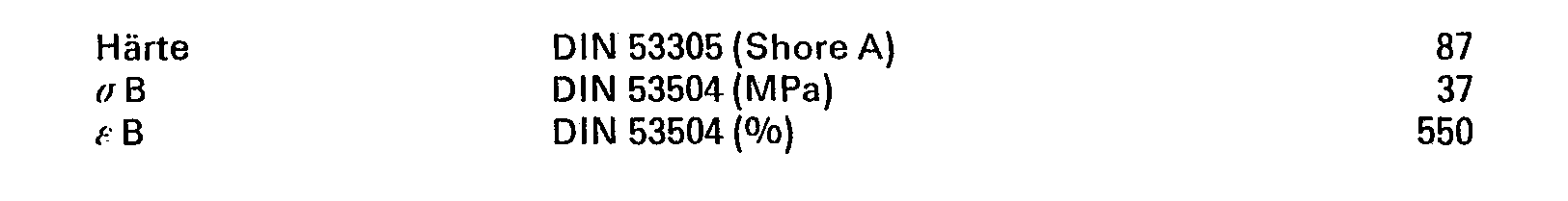
- the tires of the invention can be made from any natural or synthetic rubber whose vulcanizate values have a Shore A hardness of 45-80 and a tension value of 3.0 to 9.0 MPa at 300% elongation. Natural rubber, styrene-butadiene rubber, polybutadiene and ethylene / propylene terpolymer rubber are particularly suitable.
- the weight of the tire is comparable to that of normal pneumatic tires.
- the tires can e.g. B. with the following rubber mixture.
- any reactive, hardenable plastic mixture can be used for the plastic reinforcement in the tire base.
- the reinforcement preferably consists of a polyurethane. You can e.g. B. with the following two recipes.
- NCO prepolymers based on adipic acid esters BBG and C 4 polyethers (molecular weight between 1000 and 5000) and aromatic isocyanates, in the first case reacted with aromatic or aliphatic di- or polyfunctional amines.
Landscapes
- Engineering & Computer Science (AREA)
- Mechanical Engineering (AREA)
- Tires In General (AREA)
- Tyre Moulding (AREA)
Description
Die Erfindung betrifft ein Verfahren zur Herstellung enes Fahrzeugreifens, insbesondere für Zweiradfahrzeuge wie Fahrräder oder Rollstühle, aus einem der Felgenkontur angepaßten Reifenfuß, Seitenwänden und einer Lauffläche, die derart ineinander übergehen, daß sie einen umlaufenden geschlossenen Hohlraum bilden, wobei der Reifen durch Extrusion hergestellt wird, das extrudierte Profil vulkanisiert und auf die Felge aufgezogen wird und anschließend ein umlaufender Verstärkungsring aus Kunststoff zur Versteifung des Reifenfußes in den Reifen eingebracht wird.The invention relates to a method for producing a vehicle tire, in particular for two-wheeled vehicles such as bicycles or wheelchairs, from a tire base adapted to the rim contour, side walls and a tread which merge into one another in such a way that they form a circumferential closed cavity, the tire being produced by extrusion , the extruded profile is vulcanized and mounted on the rim and then a circumferential reinforcement ring made of plastic is inserted into the tire to stiffen the tire foot.
Der Verstärkungsring wird bei diesem aus der US-A 3 948 303 bekannten Verfahren aus einer Nylonstange geformt, deren Enden nach dem Einbringen dieser Stange in den Hohlraum des Reifens mit einer Klemmhülse miteinander verbunden werden. Diese Klemmhülse verdickt den Verstärkungsring an einer Stelle des Umfangs. Außerdem können die Enden des auf den gewünschten Reifenumfang zugeschnittenen Reifenprofiles erst fest miteinander verbunden werden, nachdem der Verstärkungsring mit der Klemmhülse geschlossen wurde. Da der Verstärkungsring jedoch den Reifenfuß fest umschließt um einen Preßsitz der Reifen auf der Felge zu gewährleisten, ist die zum Schließen des Verstärkungsringes notwendige Verschiebung des Reifenprofils relativ zum Verstärkungsring schwierig. Aufgabe der Erfindung ist es daher, den Verstärkungsring auf einfache Weise in den Reifen einzubringen nachdem die Stirnseiten des Reifenprofils auf Stoß fest miteinander verbunden worden sind.In this method known from US Pat. No. 3,948,303, the reinforcement ring is formed from a nylon rod, the ends of which are connected to one another with a clamping sleeve after the introduction of this rod into the cavity of the tire. This clamping sleeve thickens the reinforcement ring at one point on the circumference. In addition, the ends of the tire profile tailored to the desired tire circumference can only be firmly connected to one another after the reinforcement ring has been closed with the clamping sleeve. However, since the reinforcement ring tightly encloses the tire foot in order to ensure an interference fit of the tires on the rim, the displacement of the tire profile relative to the reinforcement ring necessary for closing the reinforcement ring is difficult. The object of the invention is therefore to introduce the reinforcement ring into the tire in a simple manner after the end faces of the tire tread have been firmly connected to one another in a butt joint.
Diese Aufgabe wird bei dem Verfahren der eingangs genannten Art dadurch gelöst, daß eine dem Querschnitt des Verstärkungsringes entsprechende umlaufende kanalförmige Aussparung im Reifenfuß vorgesehen ist, die über mindestens einen Anspritzkanal mit einer aushärtbaren Kunststoffmischung gefüllt wird.This object is achieved in the method of the type mentioned in the introduction that a circumferential channel-shaped recess corresponding to the cross section of the reinforcement ring is provided in the tire foot, which is filled with a curable plastic mixture via at least one injection channel.
Die Reifen sind beim Übergang der Seitenwände in den Reifenfuß eingebuchtet, so daß die Seitenwände durch das Felgenhorn abgestützt sind. Der Reifenfuß selbst ist in seiner Form der Felgenkontur angepaßt. Dadurch wird zusammen mit der umlaufenden Kunststoffverstärkung im Reifenfluß ein sicherer Preßsitz der Reifen auf der Felge erreicht. Die Kunststoffverstärkung hat i. a. einen bandförmigen, annähernd rechteckigen Querschnitt (vgl. Figur 1 und 2). Vorzugsweise ist die Kunststoffverstärkung parallel zur Felgenschräge orientiert und kann dann z. B. einen winkelförmigen Querschnitt haben (vgl. Figur 3).The tires are indented in the tire foot at the transition of the side walls, so that the side walls are supported by the rim flange. The shape of the tire foot itself is adapted to the rim contour. This, together with the all-round plastic reinforcement in the tire flow, ensures a secure press fit of the tires on the rim. The plastic reinforcement has i. a. a band-shaped, approximately rectangular cross-section (see FIGS. 1 and 2). Preferably, the plastic reinforcement is oriented parallel to the slope of the rim and can then, for. B. have an angular cross-section (see FIG. 3).
Zweckmäßigerweise werden die Reifen zunächst mit einer geeigneten Aussparung im Reifenfuß hergestellt, in die dann die Kunststoffverstärkung eingebracht wird. Besonders vorteilhaft und wirtschaftlich stellt man die Reifen durch Extrusion entsprechender Profilkörper und anschließender Vulkanisation her. Die Vulkanisation kann kontinuierlich, z. B. durch Ultrahochfrequenz erfolgen. Die extrudierten und vulkanisierten Profile werden auf die den gewünschten Reifenumfang entsprechende Länge zugeschnitten und ihre Stirnseiten auf Stoß fest miteinander verbunden. Es ist also nicht notwendig für jeden Reifendurchmesser eine besondere teure Vulkanisationsform bereitzuhalten.The tires are expediently first produced with a suitable recess in the tire foot, into which the plastic reinforcement is then introduced. The tires are produced particularly advantageously and economically by extrusion of corresponding tread bodies and subsequent vulcanization. The vulcanization can be carried out continuously, e.g. B. done by ultra-high frequency. The extruded and vulcanized treads are cut to the length required for the desired tire circumference and their end faces are firmly joined together. It is therefore not necessary to have a special, expensive form of vulcanization available for every tire diameter.
In die Lauffläche der extrudierten Längsprofile kann vor der Vulkanisation durch Querwalzen ein Profil geprägt werden, welches unter Umständen die Griffigkeit des Reifen verbessert.A profile can be embossed into the tread of the extruded longitudinal profiles before vulcanization, which may improve the grip of the tire.
Die Fertigung gegenüber den bisher üblichen Luftreifen wird vereinfacht, da wegen des einheitlichen Werkstoffes der Reifen nicht lagenweise aufgebaut werden muß. Die wirtschaftliche Ersparnis ist also groß.The production compared to the previously customary pneumatic tires is simplified because the tires do not have to be built up in layers because of the uniform material. So the economic savings are great.
Der vorgefertigte Reifen wird über das Felgenhorn geschoben. Das Aufziehen des Reifens ist einfach, da die Vorspannung in Umfangsrichtung nur 0,5 bis 1% betragen muß.The prefabricated tire is pushed over the rim flange. Tire mounting is easy because the circumferential preload only needs to be 0.5 to 1%.
Die Kunststoffverstärkung wird vorzugsweise erst nach Herstellung und Aufziehen des Reifens auf die Felge in die Aussparung im Reifenfuß eingebracht. Dazu wird über Anspritzkanäle in der Felge ein flüssiges reaktionsfähiges Kunststoffgemisch in die Aussparung eingedrückt und ausgehärtet. Bevorzugt sind Kunststoffgemische mit Reaktionszeiten von etwa 10 Sekunden. Nach der Aushärtung liegt ein einwandfreier Formschluß zur Übertragung der Antriebs- und Seitenkräfte vor, so daß die Kräfte des Fahrzeugs sicher auf die federnden Seitenwände und über die Lauffläche auf den Untergrund übertragen werden.The plastic reinforcement is preferably introduced into the recess in the tire foot only after the tire has been manufactured and mounted on the rim. For this purpose, a liquid, reactive plastic mixture is pressed into the recess and cured via injection channels in the rim. Plastic mixtures with reaction times of about 10 seconds are preferred. After curing, there is a perfect positive connection for the transmission of the drive and side forces, so that the forces of the vehicle are safely transmitted to the resilient side walls and via the tread to the ground.
Die Reifen besitzen gute Rundlaufeigenschaften und eine hohe Seitenstabilität. Auch bei höherer Geschwindigkeit auftretende Zentrifugalkräfte sind nicht in der Lage, die Reifen von der Felge zu lösen. Die Reifen sind unempfindlich gegen Schnitt- und Nagelbeschädigungen da keine Druckluft als Federungselement vorhanden ist, die entweichen kann. Sie sind besonders für Krankenfahrstühle oder Zweiradfahrzeuge geeignet.The tires have good concentricity and high lateral stability. Even at higher speeds, centrifugal forces are unable to detach the tires from the rim. The tires are insensitive to cut and nail damage because there is no compressed air as a suspension element that can escape. They are particularly suitable for medical elevators or two-wheel vehicles.
Verschiedene Ausführungsformen der erfindungsgemäßen Reifen sind in Fig. 1-4 dargestellt. Es zeigen:
- Fig. 1 einen Querschnitt durch einen bevorzugten Reifen,
- Fig. 2 und 3 Querschnitte durch zwei weitere Ausführungsformen und
- Fig. 4 einen Längsschnitt durch einen bevorzugten Reifen entlang der Linie A-A in Fig. 1.
- 1 shows a cross section through a preferred tire,
- 2 and 3 cross sections through two further embodiments and
- 4 shows a longitudinal section through a preferred tire along the line AA in FIG. 1.
- In Fig. 1 ist ein extrudierter Reifen auf der Felge im Querschnitt dargestellt. Die im Zenit vorhandene maximale Dicke der Lauffläche (1) mit Profilen (2) geht unter stetiger Verjüngerung in die Seitenwand (3) über, an die sich der umlaufende Reifenfuß (4), der auf die Felgenkontur (5) abgestimmt ist, anschließt. Der ellipsenförmige Hohlraum (6) dient dazu, den Federkomfort des Reifen zu gewährleisten. Im Reifenfuß befindet sich eine umlaufende Aussparung (7), die an 2 Stellen des Umfangs mit 2 Einspritzkanälen (8) verbunden ist. Die Aussparung (7) wird über die beiden Einspritzkanäle (8) mit einer schnellhärtenden Kunststoffmischung gefüllt.In Fig. 1, an extruded tire on the rim is shown in cross section. The maximum thickness of the tread (1) with profiles (2) present in the zenith merges continuously into the side wall (3), which is followed by the circumferential tire foot (4), which is matched to the rim contour (5). The elliptical cavity (6) serves to ensure the spring comfort of the tire most. There is a circumferential recess (7) in the tire foot, which is connected to 2 injection channels (8) at two points on the circumference. The recess (7) is filled with a quick-curing plastic mixture via the two injection channels (8).
- Fig. 2 zeigt einen Querschnitt durch einen Reifen mit Lauffläche (1), Profilen (2), Reifenfuß (4) mit Aussparung (7), Felge (5) und Anspritzkanal (8). Zur Abstützung der Seitenwand (3) verläuft hier deren äußere Konturlinie (9) bogenförmig zum Felgenhorn. Dementsprechend ist der Hohlraum (6) zwischen Lauffläche (1) und Reifenfuß (4) glockenförmig ausgebildet, so daß der Reifen eine vorgegebene Einfederungskennlinie besitzt.Fig. 2 shows a cross section through a tire with tread (1), profiles (2), tire foot (4) with recess (7), rim (5) and injection channel (8). To support the side wall (3), the outer contour line (9) here runs in an arc to the rim flange. Accordingly, the cavity (6) between the tread (1) and the tire foot (4) is bell-shaped, so that the tire has a predetermined deflection characteristic.
- Fig. 3 zeigt einen Querschnitt durch einen ähnlichen Reifen wie in Fig. 2 mit Lauffläche (1), Profilen (2), Seitenwand (3) mit Konturlinie (9), Reifenfuß (4), Felge (5) und Anspritzkanal (8).Fig. 3 shows a cross section through a similar tire as in Fig. 2 with tread (1), profiles (2), side wall (3) with contour line (9), tire foot (4), rim (5) and injection channel (8) .
Die Aussparung (7) im Reifenfuß (4) verläuft hier jedoch parallel zur Felgenschräge und hat daher die Form eines Winkels. Dementsprechend ist der Hohlraum (6) keilförmig ausgebildet.However, the recess (7) in the tire foot (4) runs parallel to the rim slope and therefore has the shape of an angle. Accordingly, the cavity (6) is wedge-shaped.
Fig. 4 zeigt einen Längsschnitt durch den Reifen der Fig. 1 entlang A-A mit Lauffläche (1), Hohlraum (6), Aussparung (7) und die darin mündenden Anspritzkanäle (8).Fig. 4 shows a longitudinal section through the tire of Fig. 1 along A-A with tread (1), cavity (6), recess (7) and the injection channels (8) opening therein.
Die Reifen der Erfindung können aus jedem beliebigen Natur- oder Synthesekautschuk hergestellt werden, dessen Vulkanisatwerte eine Shore-A-Härte von 45-80 und einen Spannungswert von 3,0 bis 9,0 MPa bei 300% Dehnung aufweisen. Besonders geeignet sind Naturkautschuk, Styrolbutadienkautschuk, Polybutadien und Ethylen/Propylen-Terpolymerisat-Kautschuk. Das Gewicht des Reifens ist dem des normalen Luftreifens vergleichbar. Die Reifen können z. B. mit der nachfolgenden Kautschukmischung hergestellt werden.


Für die Kunststoffverstärkung im Reifenfuß kann im Prinzip jede reaktionsfähige, härtbare Kunststoffmischung verwendet werden. Vorzugsweise besteht die Verstärkung aus einem Polyurethan. Sie kann z. B. mit den beiden folgenden Rezepturen hergestellt werden.In principle, any reactive, hardenable plastic mixture can be used for the plastic reinforcement in the tire base. The reinforcement preferably consists of a polyurethane. You can e.g. B. with the following two recipes.

![]()
![]()


Es handelt sich in beiden Fällen um NCO-Prepolymere auf der Basis von Adipinsäureestern, BBG-und C4-Polyethern (Molgewicht zwischen 1000 und 5000) und aromatischen Isocyanaten, im ersten Fall mit aromatischen oder aliphatischen di- oder mehrfunktionellen Aminen umgesetzt.Both are NCO prepolymers based on adipic acid esters, BBG and C 4 polyethers (molecular weight between 1000 and 5000) and aromatic isocyanates, in the first case reacted with aromatic or aliphatic di- or polyfunctional amines.
Claims (3)
Applications Claiming Priority (2)
| Application Number | Priority Date | Filing Date | Title |
|---|---|---|---|
| DE3101408 | 1981-01-17 | ||
| DE19813101408 DE3101408A1 (en) | 1981-01-17 | 1981-01-17 | VEHICLE TIRE |
Publications (2)
| Publication Number | Publication Date |
|---|---|
| EP0056579A1 EP0056579A1 (en) | 1982-07-28 |
| EP0056579B1 true EP0056579B1 (en) | 1985-03-27 |
Family
ID=6122833
Family Applications (1)
| Application Number | Title | Priority Date | Filing Date |
|---|---|---|---|
| EP82100043A Expired EP0056579B1 (en) | 1981-01-17 | 1982-01-07 | Method of producing a vehicle tyre, especially vehicles with two wheels, such as bicycles, or wheel chairs |
Country Status (5)
| Country | Link |
|---|---|
| US (1) | US4493355A (en) |
| EP (1) | EP0056579B1 (en) |
| JP (1) | JPS57140206A (en) |
| DE (2) | DE3101408A1 (en) |
| IN (1) | IN157948B (en) |
Families Citing this family (20)
| Publication number | Priority date | Publication date | Assignee | Title |
|---|---|---|---|---|
| DE3732505A1 (en) * | 1987-09-26 | 1989-04-13 | Tente Rollen Gmbh & Co | IMPELLER, ESPECIALLY FOR ROLLERS |
| US4872063A (en) * | 1988-03-17 | 1989-10-03 | Optum Corporation | Method to increase scanning resolution using a synthetic aperture |
| GB8827337D0 (en) * | 1988-11-23 | 1988-12-29 | Medical Res Council | Nucleoside analogues |
| GB8913202D0 (en) * | 1989-06-08 | 1989-07-26 | Kauzlarich James J | Maintenance free vehicle and cart tyre |
| US6303060B1 (en) | 1997-10-20 | 2001-10-16 | Pacific Circle Technologies, Inc. | Method of making non-deflatable tire and wheel assembly |
| BR9801949C1 (en) * | 1998-04-23 | 2000-12-12 | Ciro Nogueira | Non-pneumatic tire for industrial and off-road use and manufacturing process |
| HUP9902483A3 (en) | 1999-01-05 | 2003-10-28 | New Tech Tire Llc New York | Tyre |
| US6896020B1 (en) | 2000-06-30 | 2005-05-24 | Tbdc, Llc | Tire inflated with a plurality of balls |
| DE20104394U1 (en) * | 2001-03-06 | 2001-06-13 | Ralf Bohle GmbH & Co. KG, 51580 Reichshof | Wheelchair tires |
| US20030024622A1 (en) * | 2001-05-04 | 2003-02-06 | Chrobak Dennis S. | Anisotropic homogeneous elastomeric closed torus tire design & method of manufacture |
| DE602006021694D1 (en) * | 2006-02-15 | 2011-06-16 | Fiat Ricerche | Vehicle wheel, especially for two-wheelers |
| US7506878B2 (en) * | 2006-05-08 | 2009-03-24 | William Kurt Feick | Self-leveling tire |
| FR2997653B1 (en) * | 2012-11-07 | 2017-12-08 | Otico | SEMI-HOLLOW PNEUMATIC TIRE WITH IMPROVED PROFILE AND ROLLING MEMBER EQUIPPED WITH SUCH TIRES |
| CN103057356A (en) * | 2013-01-25 | 2013-04-24 | 厦门连科工业有限公司 | Low-speed flat inflation-free tire |
| US9815331B2 (en) * | 2014-02-11 | 2017-11-14 | Xiamen Lenco Co., Ltd. | Combined tyre |
| US20160303910A1 (en) * | 2015-04-17 | 2016-10-20 | Xiamen Lenco Co.,Ltd. | Combined Tyre |
| US20170282648A1 (en) * | 2016-04-01 | 2017-10-05 | Fredrick Taylor | Semi-pneumatic tire |
| US20180056731A1 (en) * | 2016-08-29 | 2018-03-01 | Tire Spine, LLC | Run flat tire and method of making same |
| FR3056879B1 (en) * | 2016-09-30 | 2019-06-14 | Otico | PNEUMATIC ELEMENT OF AGRICULTURAL TOOL COMPRISING A RIGID TOP |
| CN114161881B (en) * | 2020-09-11 | 2024-12-03 | 深圳市道瑞轮胎有限公司 | Electric motorcycle tire with multiple elastic supports |
Family Cites Families (11)
| Publication number | Priority date | Publication date | Assignee | Title |
|---|---|---|---|---|
| US1466133A (en) * | 1921-09-13 | 1923-08-28 | Carl G Lundstrom | Resilient tire |
| US2345068A (en) * | 1940-08-29 | 1944-03-28 | Gen Tire & Rubber Co | Vehicle tire |
| BE634706A (en) * | 1963-07-09 | |||
| IT953581B (en) * | 1972-03-31 | 1973-08-10 | Pirelli | METHOD FOR FIXING A PNEUMATIC COVER TO A RIM AND PNEUMATIC WHEEL THUS OBTAINED |
| US3948303A (en) * | 1974-01-28 | 1976-04-06 | Patrick Ernest G | Replaceable resilient tire |
| US4033395A (en) * | 1975-03-06 | 1977-07-05 | Berg Winfred M | Continuous plastic tire body and tire |
| CA1032455A (en) * | 1975-05-06 | 1978-06-06 | William O. Sassaman | Molded integral flat-proof tire and method of making |
| DE2845310A1 (en) * | 1978-10-18 | 1980-04-24 | Bayer Ag | TIRES FOR SLOW DRIVING VEHICLES |
| JPS5559003A (en) * | 1978-10-27 | 1980-05-02 | Fuji Shoji Kk | Round tire |
| EP0017223A1 (en) * | 1979-04-09 | 1980-10-15 | The Firestone Tire & Rubber Company | Non-pneumatic bicycle tire |
| JPS5643010A (en) * | 1979-09-12 | 1981-04-21 | Honda Motor Co Ltd | Pneumatic tire |
-
1981
- 1981-01-17 DE DE19813101408 patent/DE3101408A1/en not_active Withdrawn
-
1982
- 1982-01-07 EP EP82100043A patent/EP0056579B1/en not_active Expired
- 1982-01-07 DE DE8282100043T patent/DE3262729D1/en not_active Expired
- 1982-01-11 US US06/338,356 patent/US4493355A/en not_active Expired - Fee Related
- 1982-01-14 JP JP57003548A patent/JPS57140206A/en active Pending
- 1982-05-25 IN IN395/DEL/82A patent/IN157948B/en unknown
Also Published As
| Publication number | Publication date |
|---|---|
| IN157948B (en) | 1986-07-26 |
| JPS57140206A (en) | 1982-08-30 |
| DE3262729D1 (en) | 1985-05-02 |
| EP0056579A1 (en) | 1982-07-28 |
| US4493355A (en) | 1985-01-15 |
| DE3101408A1 (en) | 1982-09-02 |
Similar Documents
| Publication | Publication Date | Title |
|---|---|---|
| EP0056579B1 (en) | Method of producing a vehicle tyre, especially vehicles with two wheels, such as bicycles, or wheel chairs | |
| EP0860304A2 (en) | Vehicle wheel with pneumatic tyre | |
| DE19650314A1 (en) | Annular wheel component with variable stiffness | |
| DE2627951A1 (en) | EXPANDABLE BLADDER FOR A TIRE BUILDING MACHINE FOR SINGLE-STAGE OR TWO-STAGE MANUFACTURING, IN PARTICULAR OF RADIAL-LAYER TIRES | |
| DE2813742A1 (en) | VALVE FOR TIRES | |
| DE3242865A1 (en) | SUPPORT DEVICE FOR PREVENTING FLAT TIRES | |
| DE3111566A1 (en) | AIR TIRE ARRANGEMENT | |
| DE60106079T2 (en) | COMPRISING AN AIR TUBE AND SEALING COMPONENT AND METHOD OF MANUFACTURE | |
| DE2651876A1 (en) | TIRES AND THE METHOD OF MANUFACTURING IT | |
| EP0076412B1 (en) | Vehicle tyre | |
| DE29713290U1 (en) | Roller conveyor system | |
| DE2930479A1 (en) | PRESSURELESS TIRE | |
| DE4209687A1 (en) | Vehicle tyre with long service life - has two similar halves bonded together, each having tread, so that when one tread is worn out tyre is reversed and inner tread faces outwards | |
| EP0561762B1 (en) | Tire-flap | |
| EP0211301B1 (en) | Valve for a bicycle tube and method for its manufacture | |
| DE10123008A1 (en) | Pressureless vehicle tire, comprises a fiber-reinforced polymer strip formed into a coil spring wrapped as a closed ring around a rim and embedded on the outside in a elastomer tread strip | |
| DE2845310A1 (en) | TIRES FOR SLOW DRIVING VEHICLES | |
| DE2441235C2 (en) | Vehicle wheel with a pneumatic tire | |
| EP0003782B1 (en) | Extrusion tyres and methods and apparatus for their manufacture | |
| DE19822819A1 (en) | Puncture-proof foam-filled bicycle tire production | |
| DE1182143B (en) | Conveyor belt | |
| DE2729444A1 (en) | TIRES FOR VEHICLE BIKES | |
| DE2804958A1 (en) | VEHICLE AIR TIRES | |
| DE2442401B2 (en) | Rubber tread for renewing the tread of a used tire | |
| EP0081728B1 (en) | Detachable securing of a puncture-resistant tyre |
Legal Events
| Date | Code | Title | Description |
|---|---|---|---|
| PUAI | Public reference made under article 153(3) epc to a published international application that has entered the european phase |
Free format text: ORIGINAL CODE: 0009012 |
|
| 17P | Request for examination filed |
Effective date: 19820107 |
|
| AK | Designated contracting states |
Designated state(s): BE DE FR GB IT NL |
|
| ITF | It: translation for a ep patent filed | ||
| GRAA | (expected) grant |
Free format text: ORIGINAL CODE: 0009210 |
|
| AK | Designated contracting states |
Designated state(s): BE DE FR GB IT NL |
|
| REF | Corresponds to: |
Ref document number: 3262729 Country of ref document: DE Date of ref document: 19850502 |
|
| ET | Fr: translation filed | ||
| PLBE | No opposition filed within time limit |
Free format text: ORIGINAL CODE: 0009261 |
|
| STAA | Information on the status of an ep patent application or granted ep patent |
Free format text: STATUS: NO OPPOSITION FILED WITHIN TIME LIMIT |
|
| 26N | No opposition filed | ||
| PGFP | Annual fee paid to national office [announced via postgrant information from national office to epo] |
Ref country code: NL Payment date: 19890131 Year of fee payment: 10 |
|
| PGFP | Annual fee paid to national office [announced via postgrant information from national office to epo] |
Ref country code: DE Payment date: 19891222 Year of fee payment: 9 |
|
| PGFP | Annual fee paid to national office [announced via postgrant information from national office to epo] |
Ref country code: FR Payment date: 19891227 Year of fee payment: 9 |
|
| ITTA | It: last paid annual fee | ||
| PGFP | Annual fee paid to national office [announced via postgrant information from national office to epo] |
Ref country code: GB Payment date: 19900131 Year of fee payment: 9 Ref country code: BE Payment date: 19900131 Year of fee payment: 9 |
|
| PG25 | Lapsed in a contracting state [announced via postgrant information from national office to epo] |
Ref country code: GB Effective date: 19910107 |
|
| PG25 | Lapsed in a contracting state [announced via postgrant information from national office to epo] |
Ref country code: BE Effective date: 19910131 |
|
| PG25 | Lapsed in a contracting state [announced via postgrant information from national office to epo] |
Ref country code: NL Effective date: 19910801 |
|
| GBPC | Gb: european patent ceased through non-payment of renewal fee | ||
| NLV4 | Nl: lapsed or anulled due to non-payment of the annual fee | ||
| PG25 | Lapsed in a contracting state [announced via postgrant information from national office to epo] |
Ref country code: FR Effective date: 19910930 |
|
| PG25 | Lapsed in a contracting state [announced via postgrant information from national office to epo] |
Ref country code: DE Effective date: 19911001 |
|
| REG | Reference to a national code |
Ref country code: FR Ref legal event code: ST |