EP0061573A1 - Nuclear steam supply system and method of installation - Google Patents
Nuclear steam supply system and method of installation Download PDFInfo
- Publication number
- EP0061573A1 EP0061573A1 EP82101112A EP82101112A EP0061573A1 EP 0061573 A1 EP0061573 A1 EP 0061573A1 EP 82101112 A EP82101112 A EP 82101112A EP 82101112 A EP82101112 A EP 82101112A EP 0061573 A1 EP0061573 A1 EP 0061573A1
- Authority
- EP
- European Patent Office
- Prior art keywords
- unit
- containment
- steam supply
- supply system
- site
- Prior art date
- Legal status (The legal status is an assumption and is not a legal conclusion. Google has not performed a legal analysis and makes no representation as to the accuracy of the status listed.)
- Granted
Links
Images





Classifications
-
- G—PHYSICS
- G21—NUCLEAR PHYSICS; NUCLEAR ENGINEERING
- G21D—NUCLEAR POWER PLANT
- G21D1/00—Details of nuclear power plant
- G21D1/006—Details of nuclear power plant primary side of steam generators
-
- G—PHYSICS
- G21—NUCLEAR PHYSICS; NUCLEAR ENGINEERING
- G21C—NUCLEAR REACTORS
- G21C13/00—Pressure vessels; Containment vessels; Containment in general
-
- G—PHYSICS
- G21—NUCLEAR PHYSICS; NUCLEAR ENGINEERING
- G21D—NUCLEAR POWER PLANT
- G21D1/00—Details of nuclear power plant
-
- Y—GENERAL TAGGING OF NEW TECHNOLOGICAL DEVELOPMENTS; GENERAL TAGGING OF CROSS-SECTIONAL TECHNOLOGIES SPANNING OVER SEVERAL SECTIONS OF THE IPC; TECHNICAL SUBJECTS COVERED BY FORMER USPC CROSS-REFERENCE ART COLLECTIONS [XRACs] AND DIGESTS
- Y02—TECHNOLOGIES OR APPLICATIONS FOR MITIGATION OR ADAPTATION AGAINST CLIMATE CHANGE
- Y02E—REDUCTION OF GREENHOUSE GAS [GHG] EMISSIONS, RELATED TO ENERGY GENERATION, TRANSMISSION OR DISTRIBUTION
- Y02E30/00—Energy generation of nuclear origin
-
- Y—GENERAL TAGGING OF NEW TECHNOLOGICAL DEVELOPMENTS; GENERAL TAGGING OF CROSS-SECTIONAL TECHNOLOGIES SPANNING OVER SEVERAL SECTIONS OF THE IPC; TECHNICAL SUBJECTS COVERED BY FORMER USPC CROSS-REFERENCE ART COLLECTIONS [XRACs] AND DIGESTS
- Y02—TECHNOLOGIES OR APPLICATIONS FOR MITIGATION OR ADAPTATION AGAINST CLIMATE CHANGE
- Y02E—REDUCTION OF GREENHOUSE GAS [GHG] EMISSIONS, RELATED TO ENERGY GENERATION, TRANSMISSION OR DISTRIBUTION
- Y02E30/00—Energy generation of nuclear origin
- Y02E30/30—Nuclear fission reactors
Definitions
- the present invention relates to a prefabricated nuclear steam supply system unit and method of installation.
- the present invention resides in a nuclear steam supply system adapted to be assembled at a manufacturing site so as to be floated along commercially navigable waterways to a selected use site, said system including a nuclear reactor and steam generators and other necessary equipment within a reactor containment, characterized in that said containment is a floatable body and said equipment is arranged essentially along a line so as to maintain the containment relatively narrow and said containment further has an upper removable region so as to permit reduction of height of said containment for permitting movement of said system beneath bridges, and that all major system components located within said containment are arranged at a height below said upper removable region.
- a nuclear steam supply system unit is hereby provided that is constructed to include a barge or flotation base as an integrated portion thereof.
- the system may be tested for operability and safety at the factory and then towed along navigable coastal or inland waterways, or overseas to foreign locations to a prepared foundation site at its point of use.
- the overall unit is so constructed and arranged as to permit removal of top and side sections to permit passage under low bridges and through narrow locks without requiring disassembly of safety class piping and wiring.
- the basic concept of the present invention resides in the provision of a nuclear steam supply system unit, NSSSU, mounted on integrally formed flotation base 2 so constructed and arranged as to enable such unit to be tested for safety and performance at the factory where it is constructed and thereafter towed while being floated to a pre-constructed foundation at a selected use site overseas or along the coast of the United States, or along a major navigable river or lake accessible from the coast- line, such as along the Mississippi, Missouri, Ohio, etc. rivers, or along the coast of the Great Lakes in the United States and North America as accessible by way of the St. Lawrence River. It is intended that the NSSSU be complete with respect to including all of the operational and safety equipment necessary to function as a source of steam supply.
- the NSSSU includes a fore and aft mid-portion that functions as a nuclear steam supply section, NSSS, in affiliation with a control and instrument section C&IS at one end of the NSSSU and a mechanical auxiliaries and safety power supply section MA&SPSS at the other end of the NSSSU.
- NSSS nuclear steam supply section
- the unit includes a horizontal generally cylindrical steel containment shell encasing the reactor and the steam generators, with all safety related components, equipment, diesel power supplies, controls and devices incorporated in the unit on the flotation base for and aft of the shell.
- Cellular portions of the flotation base are adapted to be filled with concrete for shielding after arrival at the installation site to allow for shallow- draft flotation during inland waterway transport. Some cells may be cement-filled initially for float-leveling trim.
- the primary salient feature of the NSSSU of the present invention resolves around the construction of the unit such that substantially all of the dynamic functional operational parts of the several longitudinal sections C&IS, NSSS, and the MA&SPSS all lie within a widthwise and heightwise region of the unit capable of passing under navigable bridges along the waterway and into and out of locks along the waterway without requiring any substantial significant disassembly of such functional components as factory- installed within the NSSSU.
- the overall height of the unit as originally assembled at the factory is adapted to be altered to suit different bridge heights by removal at the factory and reinstallation at the use site, of the several upper structural housing portions of the unit with no or substantially little disturbance to the functional dynamic operational components of the system disposed within the unit.
- a NSSSU might have a draft of nine feet and an overall height of one hundred and five feet for towing along the coastal areas of the United States, for example, and through the lower regions of the Mississippi River up to Cairo, Illinois, for example.
- the unit can be adapted for passages under lower bridges of these rivers by removal of the upper section 4 of the nuclear steam supply section of the NSSSU, and finally uppermost regions of the Ohio and Missouri Rivers can be traversed by the unit by further removal of still another upper section 3 of the housing portion of the unit.
- the overall height of the unit may be in the realm of sixty-seven feet, for example, with a nine foot draft.
- the longitudinal side regions 5 of the flotation base 2, together with side regions 6 of a steel containment shell 7 of the NSSS can be removed.
- the width of the unit may be such as seventy-five feet wide and the overall height can be allowed to be one hundred and five feet with the upper sections 3 and 4 intact.
- the length of the unit can be about five hundred and ninety feet long and be able to pass through the locks along the aforementioned inland waterways.
- the flotation base 2 provides less lift and accordingly the water level draft tends to be in the order of fifteen feet rather than the nine-foot draft of the wider configuration of the flotation base 2.
- the nuclear steam supply section is integrally mounted on the flotation base 2, which is of hollow steel construction and of flat hull-like configuration having the longitudinal side regions 5 removably attached thereto.
- the steel containment shell-7 is generally cylindrical with spherical end regions 8. The shell is mounted on the flotation base 2 and attached thereto as by weldments (not shown).
- a steam line 14 exits from the secondary side of each of the steam generators 11 for delivery to a steam operated turbine generator assembly (not shown) ultimately to be affiliated with the unit of the present invention.
- Disposed around the reactor vessel 10 and around the steam generators 11 are a number of hollow steel wall sections 15 that are adapted to be filled with concrete for radiation shielding purposes once the unit is installed at its ultimate use site.
- a number of stairways 16 vertically interconnect a plurality of horizontal working platforms 17 disposed within the interior of the shell 7 to accommodate working and operating personnel therein.
- An overhead crane 18 is provided within the shell 7 above the steam generators 11 that is movable along the cross beam 19 that in turn is capable of moving along longitudinal guide rails 20.
- different height sections are adapted to be removed from the shell 7; the uppermost region having a juncture seam along the horizontal line MA and a second and lower region having a juncture seam along the horizontal line MB, to enable passage of the shell under different height bridges that may exist along the waterways along which the unit is being towed while enroute to a use site.
- the crane 18 and cross bridge member 19 also will have to be removed to afford the lowered height for bridge clearance.
- FIG. 1 also additionally will have to be removed, as will an uppermost section 22 of the steam generator. It also will be apparent from Figs. 1, 2, 6 and 7 that an uppermost floor 24 of the sections C&IS and MA&SPSS of the nuclear steam supply system unit, NSSSU, also will need to be removed together with the portions of the shell 7 where the overall height is to be reduced to the level represented by the dot dash line MB in the several figures.
- Vertical sidewalls 26 are disposed within the interior of the shell 7, Figs. 3 and 5, which act to provide structural integrity and support for the nuclear steam supply components disposed in the nuclear steam supply section, NSSS, in the widthwise region between the removable side regions 6 when such regions are removed to accommodate passage through the narrower canal- ways and locks.
- the unit is adapted to have the longitudinal side edges 5 of the flotation base 2 removed together with the side sections 6 of the steel containment shell 7 along the dot-and-dash lines MC.
- the completed nuclear steam supply system unit NSSSU is towed to its use site location to a pre-constructed foundation, Figs. 8 and 9 on which a hollow radiation shield 31 also will have been constructed.
- Foundation 30 can be made higher than the water level 32 of the river or coastal body of water along which the use site is located by use of a dike 33.
- An artificial lake 34 can be constructed to enable the floating of the NSSSU into the shield 31 and onto the foundation 30.
- the work on preparation of the foundation 30 and the shield 31 together with that of the dike 33 can occur simultaneously with the construction of the nuclear steam supply system unit, NSSSU.
- the auxiliary equipment components may be added, including the turbine generator plant (not shown) to be operated by the steam derived from the NSSSU.
- Such steam turbine generator plant may or may not be prefabricated and of the flotation type, according to the desire and need of the user.
Landscapes
- Physics & Mathematics (AREA)
- Engineering & Computer Science (AREA)
- Plasma & Fusion (AREA)
- General Engineering & Computer Science (AREA)
- High Energy & Nuclear Physics (AREA)
- Structure Of Emergency Protection For Nuclear Reactors (AREA)
- Foundations (AREA)
- Conveying And Assembling Of Building Elements In Situ (AREA)
Abstract
Description
- The present invention relates to a prefabricated nuclear steam supply system unit and method of installation.
- Advantages would appear to result in the provision of a nuclear steam supply system that can be of standardized construction, prefabricated, inspected and tested substantially at the factory site, and transported as a unit to different intracontinental and intercontinental use sites.
- It is therefore the principal object of the present invention to provide a nuclear stream supply system and method which permits manufacture at a manufacturing site and installation at a utility site of an essentially completed system. With this object in view, the present invention resides in a nuclear steam supply system adapted to be assembled at a manufacturing site so as to be floated along commercially navigable waterways to a selected use site, said system including a nuclear reactor and steam generators and other necessary equipment within a reactor containment, characterized in that said containment is a floatable body and said equipment is arranged essentially along a line so as to maintain the containment relatively narrow and said containment further has an upper removable region so as to permit reduction of height of said containment for permitting movement of said system beneath bridges, and that all major system components located within said containment are arranged at a height below said upper removable region.
- A nuclear steam supply system unit, NSSSU, is hereby provided that is constructed to include a barge or flotation base as an integrated portion thereof. The system may be tested for operability and safety at the factory and then towed along navigable coastal or inland waterways, or overseas to foreign locations to a prepared foundation site at its point of use. The overall unit is so constructed and arranged as to permit removal of top and side sections to permit passage under low bridges and through narrow locks without requiring disassembly of safety class piping and wiring.
- The basic concept of the present invention resides in the provision of a nuclear steam supply system unit, NSSSU, mounted on integrally formed
flotation base 2 so constructed and arranged as to enable such unit to be tested for safety and performance at the factory where it is constructed and thereafter towed while being floated to a pre-constructed foundation at a selected use site overseas or along the coast of the United States, or along a major navigable river or lake accessible from the coast- line, such as along the Mississippi, Missouri, Ohio, etc. rivers, or along the coast of the Great Lakes in the United States and North America as accessible by way of the St. Lawrence River. It is intended that the NSSSU be complete with respect to including all of the operational and safety equipment necessary to function as a source of steam supply. In this regard, the NSSSU includes a fore and aft mid-portion that functions as a nuclear steam supply section, NSSS, in affiliation with a control and instrument section C&IS at one end of the NSSSU and a mechanical auxiliaries and safety power supply section MA&SPSS at the other end of the NSSSU. - The unit includes a horizontal generally cylindrical steel containment shell encasing the reactor and the steam generators, with all safety related components, equipment, diesel power supplies, controls and devices incorporated in the unit on the flotation base for and aft of the shell.
- Inclusion of an open-ended radiation and missile shield on a foundation at the use site into which the NSSSU may be installed, enables construction work to proceed simultaneously in the field and at the factory.
- The combination of a field-built missile shield and the factory-built steel containment shell provides for double, "pump-back", containment.
- Location of the foundation above flood level can be made possible by raising the NSSSU by way of a temporary water lock during installation.
- Cellular portions of the flotation base are adapted to be filled with concrete for shielding after arrival at the installation site to allow for shallow- draft flotation during inland waterway transport. Some cells may be cement-filled initially for float-leveling trim.
- The invention will become more readily apparent from the following description of a preferred embodiment thereof shown, by way of example only, in the accompanying drawings, in which:
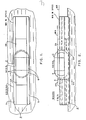
- Figs. 1 and 2 are plan and elevation views, respectively, showing schematically in outline a nuclear steam supply system unit, NSSSU, constructed in accord with features of the present invention;
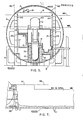
- Fig. 3 is an end elevation view of the nuclear steam supply system unit of Figs. 1 and 2;
- Fig. 4 is a side elevation view, partly in outline and partly in section, showing details of a nuclear steam supply section, NSSS, of the unit of the preceding figures;
- Fig. 5 is a lateral cross-sectional view, partly in outline, of the NSSS of the unit of the present invention;
- Fig. 6 is a side-elevational view, substantially in outline showing a control and instrumentation section, C and IS, of the unit of the present invention;
- Fig. 7 is a side-elevational view substantially in outline showing a fluid systems, auxiliary and safety power supply section of the unit of the present invention;
- Figs. 8 and 9 illustrate use site preparation and installation means for the unit of the present invention;
- Figs. 10 and 11 are plan and side elevation views showing schematically in outline a submergible barge for open-ocean transportation of the NSSSU of the present invention; and
- Figs. 12 and 13 are plan and side elevation views of a bolt-on ocean-going alternative flotation transporter for the NSSSU of the present invention.
- Referring to Figures 1, 2 and 3 the primary salient feature of the NSSSU of the present invention resolves around the construction of the unit such that substantially all of the dynamic functional operational parts of the several longitudinal sections C&IS, NSSS, and the MA&SPSS all lie within a widthwise and heightwise region of the unit capable of passing under navigable bridges along the waterway and into and out of locks along the waterway without requiring any substantial significant disassembly of such functional components as factory- installed within the NSSSU. In this regard the overall height of the unit as originally assembled at the factory is adapted to be altered to suit different bridge heights by removal at the factory and reinstallation at the use site, of the several upper structural housing portions of the unit with no or substantially little disturbance to the functional dynamic operational components of the system disposed within the unit. A NSSSU might have a draft of nine feet and an overall height of one hundred and five feet for towing along the coastal areas of the United States, for example, and through the lower regions of the Mississippi River up to Cairo, Illinois, for example. If it does continue to proceed along the Missouri or the Ohio Rivers the unit can be adapted for passages under lower bridges of these rivers by removal of the upper section 4 of the nuclear steam supply section of the NSSSU, and finally uppermost regions of the Ohio and Missouri Rivers can be traversed by the unit by further removal of still another upper section 3 of the housing portion of the unit. At this point the overall height of the unit may be in the realm of sixty-seven feet, for example, with a nine foot draft.
- To accommodate transit through narrower canal or lock regions, such as along the St. Lawrence Seaway to gain access to the Great Lakes in the North American Continent, the
longitudinal side regions 5 of theflotation base 2, together withside regions 6 of asteel containment shell 7 of the NSSS can be removed. In this case the width of the unit may be such as seventy-five feet wide and the overall height can be allowed to be one hundred and five feet with the upper sections 3 and 4 intact. In all cases the length of the unit can be about five hundred and ninety feet long and be able to pass through the locks along the aforementioned inland waterways. In the narrower width theflotation base 2 provides less lift and accordingly the water level draft tends to be in the order of fifteen feet rather than the nine-foot draft of the wider configuration of theflotation base 2. - Referring to Figs. 4 and 5, the nuclear steam supply section, NSSS, is integrally mounted on the
flotation base 2, which is of hollow steel construction and of flat hull-like configuration having thelongitudinal side regions 5 removably attached thereto. The steel containment shell-7 is generally cylindrical withspherical end regions 8. The shell is mounted on theflotation base 2 and attached thereto as by weldments (not shown). Disposed within theshell 7 there is anuclear reactor vessel 10, a pair of steam generators 11,primary coolant lines 12 for thereactor vessel 10,pumps 13 for circulating the primary coolant through thereactor vessel 10 by way of thelines 12 and into and through the primary side of the steam generators 11. Asteam line 14 exits from the secondary side of each of the steam generators 11 for delivery to a steam operated turbine generator assembly (not shown) ultimately to be affiliated with the unit of the present invention. Disposed around thereactor vessel 10 and around the steam generators 11 are a number of hollowsteel wall sections 15 that are adapted to be filled with concrete for radiation shielding purposes once the unit is installed at its ultimate use site. A number ofstairways 16 vertically interconnect a plurality ofhorizontal working platforms 17 disposed within the interior of theshell 7 to accommodate working and operating personnel therein. Anoverhead crane 18 is provided within theshell 7 above the steam generators 11 that is movable along thecross beam 19 that in turn is capable of moving alonglongitudinal guide rails 20. - In accord with the primary feature of the invention different height sections are adapted to be removed from the
shell 7; the uppermost region having a juncture seam along the horizontal line MA and a second and lower region having a juncture seam along the horizontal line MB, to enable passage of the shell under different height bridges that may exist along the waterways along which the unit is being towed while enroute to a use site. As mentioned hereinbefore, when the uppermost section of theshell 7 is removed, it will be apparent that thecrane 18 andcross bridge member 19 also will have to be removed to afford the lowered height for bridge clearance. When the height of the shell is reduced still further to the height designated by the line MB in Figures 4 and 5, upper ends ofvertical support columns 21 for thecrane cross member 19 and thetracks 20 etc. also additionally will have to be removed, as will anuppermost section 22 of the steam generator. It also will be apparent from Figs. 1, 2, 6 and 7 that anuppermost floor 24 of the sections C&IS and MA&SPSS of the nuclear steam supply system unit, NSSSU, also will need to be removed together with the portions of theshell 7 where the overall height is to be reduced to the level represented by the dot dash line MB in the several figures.Vertical sidewalls 26 are disposed within the interior of theshell 7, Figs. 3 and 5, which act to provide structural integrity and support for the nuclear steam supply components disposed in the nuclear steam supply section, NSSS, in the widthwise region between theremovable side regions 6 when such regions are removed to accommodate passage through the narrower canal- ways and locks. The unit is adapted to have thelongitudinal side edges 5 of theflotation base 2 removed together with theside sections 6 of thesteel containment shell 7 along the dot-and-dash lines MC. - By making the
flotation base 2 together with itsvertical walls 26 and all thepartitions 15 hollow, a structural rigidity is afforded which is at the same time of sufficiently light weight to enable the nuclear steam plant components to be transported by flotation and ultimately to be filled with cement to provide further rigidity and radiation shielding. Thus upon installation at the use site, replacement of the previously removed clearance-accommodating components will be reinstalled. - The completed nuclear steam supply system unit NSSSU is towed to its use site location to a pre-constructed foundation, Figs. 8 and 9 on which a
hollow radiation shield 31 also will have been constructed.Foundation 30 can be made higher than thewater level 32 of the river or coastal body of water along which the use site is located by use of adike 33. Anartificial lake 34 can be constructed to enable the floating of the NSSSU into theshield 31 and onto thefoundation 30. The work on preparation of thefoundation 30 and theshield 31 together with that of thedike 33 can occur simultaneously with the construction of the nuclear steam supply system unit, NSSSU. Once having been installed at the site, the auxiliary equipment components may be added, including the turbine generator plant (not shown) to be operated by the steam derived from the NSSSU. Such steam turbine generator plant may or may not be prefabricated and of the flotation type, according to the desire and need of the user. - Where transporting the NSSSU over a large dis= tance on the open seas, it may be preferred to employ such as a submergible barge or floating dry dock as exemplified schematically in Figures 10 and 11 to carry such NSSSU. An alternative construction can be to supplement the buoyancy characteristics of the NSSSU by an auxiliary
floating hull 37 in which the NSSSU can be fit and se- cured, as exemplified schematically in Figs. 12 and 13.
Claims (7)
Applications Claiming Priority (2)
| Application Number | Priority Date | Filing Date | Title |
|---|---|---|---|
| US24952281A | 1981-03-31 | 1981-03-31 | |
| US249522 | 1999-02-12 |
Publications (2)
| Publication Number | Publication Date |
|---|---|
| EP0061573A1 true EP0061573A1 (en) | 1982-10-06 |
| EP0061573B1 EP0061573B1 (en) | 1986-01-02 |
Family
ID=22943829
Family Applications (1)
| Application Number | Title | Priority Date | Filing Date |
|---|---|---|---|
| EP82101112A Expired EP0061573B1 (en) | 1981-03-31 | 1982-02-16 | Nuclear steam supply system and method of installation |
Country Status (5)
| Country | Link |
|---|---|
| EP (1) | EP0061573B1 (en) |
| JP (1) | JPS57178180A (en) |
| KR (1) | KR830009588A (en) |
| DE (1) | DE3268206D1 (en) |
| ZA (2) | ZA821087B (en) |
Cited By (3)
| Publication number | Priority date | Publication date | Assignee | Title |
|---|---|---|---|---|
| EP0139079A1 (en) * | 1983-10-21 | 1985-05-02 | Westinghouse Electric Corporation | Modular nuclear steam supply system and method of constructing a nuclear reactor using a modular nuclear steam supply system |
| WO2017178649A2 (en) | 2016-04-15 | 2017-10-19 | Société Technique Pour L'energie Atomique | Assembly for the construction of a nuclear reactor and corresponding methods |
| US11057968B2 (en) | 2006-02-21 | 2021-07-06 | Goji Limited | Food preparation |
Families Citing this family (1)
| Publication number | Priority date | Publication date | Assignee | Title |
|---|---|---|---|---|
| JPH08240684A (en) * | 1995-03-02 | 1996-09-17 | Ishikawajima Harima Heavy Ind Co Ltd | Nuclear power plant construction method |
Citations (4)
| Publication number | Priority date | Publication date | Assignee | Title |
|---|---|---|---|---|
| GB837031A (en) * | 1957-05-20 | 1960-06-09 | Rolls Royce | Improvements in or relating to marine vessels |
| US3752738A (en) * | 1970-07-06 | 1973-08-14 | Nuclear Services Corp | Nuclear reactor plant and multiple purpose shielding system therefor |
| GB1429685A (en) * | 1973-05-18 | 1976-03-24 | Colebrand Ltd | Apparatus and method for removing or changing a nuclear power station reactor |
| WO1980000893A1 (en) * | 1978-10-20 | 1980-05-01 | Bretagne Atel Chantiers | Reactor block and nuclear equipment utilizing it |
Family Cites Families (1)
| Publication number | Priority date | Publication date | Assignee | Title |
|---|---|---|---|---|
| JPS5129694A (en) * | 1974-09-04 | 1976-03-13 | Kajima Corp |
-
1982
- 1982-02-16 DE DE8282101112T patent/DE3268206D1/en not_active Expired
- 1982-02-16 EP EP82101112A patent/EP0061573B1/en not_active Expired
- 1982-02-18 ZA ZA821087A patent/ZA821087B/en unknown
- 1982-03-16 ZA ZA821763A patent/ZA821763B/en unknown
- 1982-03-31 KR KR1019820001396A patent/KR830009588A/en not_active Ceased
- 1982-03-31 JP JP57051456A patent/JPS57178180A/en active Pending
Patent Citations (4)
| Publication number | Priority date | Publication date | Assignee | Title |
|---|---|---|---|---|
| GB837031A (en) * | 1957-05-20 | 1960-06-09 | Rolls Royce | Improvements in or relating to marine vessels |
| US3752738A (en) * | 1970-07-06 | 1973-08-14 | Nuclear Services Corp | Nuclear reactor plant and multiple purpose shielding system therefor |
| GB1429685A (en) * | 1973-05-18 | 1976-03-24 | Colebrand Ltd | Apparatus and method for removing or changing a nuclear power station reactor |
| WO1980000893A1 (en) * | 1978-10-20 | 1980-05-01 | Bretagne Atel Chantiers | Reactor block and nuclear equipment utilizing it |
Non-Patent Citations (1)
| Title |
|---|
| NUCLEAR SAFETY, vol.15, no.6, November-December 1974, Washington D.C. (US) * |
Cited By (4)
| Publication number | Priority date | Publication date | Assignee | Title |
|---|---|---|---|---|
| EP0139079A1 (en) * | 1983-10-21 | 1985-05-02 | Westinghouse Electric Corporation | Modular nuclear steam supply system and method of constructing a nuclear reactor using a modular nuclear steam supply system |
| US4919882A (en) * | 1983-10-21 | 1990-04-24 | Westinghouse Electric Corp. | Modular nuclear steam supply system and method of constructing a nuclear reactor using a modular nuclear steam supply system |
| US11057968B2 (en) | 2006-02-21 | 2021-07-06 | Goji Limited | Food preparation |
| WO2017178649A2 (en) | 2016-04-15 | 2017-10-19 | Société Technique Pour L'energie Atomique | Assembly for the construction of a nuclear reactor and corresponding methods |
Also Published As
| Publication number | Publication date |
|---|---|
| JPS57178180A (en) | 1982-11-02 |
| DE3268206D1 (en) | 1986-02-13 |
| KR830009588A (en) | 1983-12-22 |
| EP0061573B1 (en) | 1986-01-02 |
| ZA821087B (en) | 1983-02-23 |
| ZA821763B (en) | 1983-02-23 |
Similar Documents
| Publication | Publication Date | Title |
|---|---|---|
| US4839137A (en) | Nuclear steam supply system and method of installation | |
| WO2018074977A1 (en) | System and method for reconfiguring a mobile docking apparatus for transporting, removal, installation, housing and transferring assets | |
| US4919882A (en) | Modular nuclear steam supply system and method of constructing a nuclear reactor using a modular nuclear steam supply system | |
| US4293240A (en) | Method for installing an electric power plant | |
| US3408821A (en) | Waterborne vessel | |
| EP0061573B1 (en) | Nuclear steam supply system and method of installation | |
| EP0001462A1 (en) | A method for building and transporting parts of a marine structure, a vessel for use in this method and structure built up by this method | |
| CN216428215U (en) | Pile foundation construction platform device on water | |
| EP0061675B1 (en) | Nuclear power generating facility and method of installation | |
| US5927227A (en) | Hollow concrete-walled structure for marine use | |
| FI62881B (en) | SAVING PROCEDURES | |
| RU2293386C1 (en) | Method for producing radiation-shielding packing block for placing in storage on shore | |
| KR100967887B1 (en) | Dock arrangement structure and its shipbuilding method | |
| JPS61222892A (en) | Semisubmersible type floating structure and construction method thereof | |
| JPS5953296A (en) | Fixing method of plant platform vessel | |
| Dorofeev | Alternate options of nuclear-powered submarine B-159 salvaging. Agenda item 3.3 (Presentation in English) | |
| JPH0692287A (en) | Pontoon launch method | |
| GB2314576A (en) | Offshore platform assembly | |
| GB2405170A (en) | Manoeuvering vessels under structures spanning waterways | |
| Macy | Mobile drilling platforms | |
| Kehnemuyi et al. | Site considerations associated with offshore generating stations | |
| RU2060201C1 (en) | Method of building of ship's reactor compartment | |
| Prnjak | Local strength analysis of deck truss structure joints of semi-submersible Floating Production Unit (FPU) | |
| Lee et al. | CONCEPT DESIGN OF THE TLP-TYPE OCEAN NUCLEAR POWER PLANT | |
| SU1576656A1 (en) | Method of building and carrying off-shore platform block |
Legal Events
| Date | Code | Title | Description |
|---|---|---|---|
| PUAI | Public reference made under article 153(3) epc to a published international application that has entered the european phase |
Free format text: ORIGINAL CODE: 0009012 |
|
| AK | Designated contracting states |
Designated state(s): BE DE FR GB IT NL SE |
|
| 17P | Request for examination filed |
Effective date: 19830322 |
|
| ITF | It: translation for a ep patent filed | ||
| GRAA | (expected) grant |
Free format text: ORIGINAL CODE: 0009210 |
|
| AK | Designated contracting states |
Designated state(s): BE DE FR GB IT NL SE |
|
| ET | Fr: translation filed | ||
| REF | Corresponds to: |
Ref document number: 3268206 Country of ref document: DE Date of ref document: 19860213 |
|
| PLBI | Opposition filed |
Free format text: ORIGINAL CODE: 0009260 |
|
| PLAB | Opposition data, opponent's data or that of the opponent's representative modified |
Free format text: ORIGINAL CODE: 0009299OPPO |
|
| 26 | Opposition filed |
Opponent name: INTERATOM INTERNATIONALE ATOMREAKTORBAU GMBH Effective date: 19860919 |
|
| R26 | Opposition filed (corrected) |
Opponent name: INTERATOM GMBH Effective date: 19860919 |
|
| NLR1 | Nl: opposition has been filed with the epo |
Opponent name: INTERATOM INTERNATIONALE ATOMREAKTORBAU GMBH |
|
| PGFP | Annual fee paid to national office [announced via postgrant information from national office to epo] |
Ref country code: NL Payment date: 19870228 Year of fee payment: 6 |
|
| PG25 | Lapsed in a contracting state [announced via postgrant information from national office to epo] |
Ref country code: SE Effective date: 19880217 |
|
| BERE | Be: lapsed |
Owner name: WESTINGHOUSE ELECTRIC CORP. Effective date: 19880228 |
|
| NLV4 | Nl: lapsed or anulled due to non-payment of the annual fee | ||
| RDAG | Patent revoked |
Free format text: ORIGINAL CODE: 0009271 |
|
| STAA | Information on the status of an ep patent application or granted ep patent |
Free format text: STATUS: PATENT REVOKED |
|
| GBPC | Gb: european patent ceased through non-payment of renewal fee | ||
| GBPR | Gb: patent revoked under art. 102 of the ep convention designating the uk as contracting state | ||
| 27W | Patent revoked |
Effective date: 19880716 |
|
| REG | Reference to a national code |
Ref country code: FR Ref legal event code: ST |
|
| EUG | Se: european patent has lapsed |
Ref document number: 82101112.9 Effective date: 19880927 |