EP0064257A1 - Verrottungsanlage - Google Patents
Verrottungsanlage Download PDFInfo
- Publication number
- EP0064257A1 EP0064257A1 EP19820103538 EP82103538A EP0064257A1 EP 0064257 A1 EP0064257 A1 EP 0064257A1 EP 19820103538 EP19820103538 EP 19820103538 EP 82103538 A EP82103538 A EP 82103538A EP 0064257 A1 EP0064257 A1 EP 0064257A1
- Authority
- EP
- European Patent Office
- Prior art keywords
- cells
- cell
- plant according
- rotting plant
- rotting
- Prior art date
- Legal status (The legal status is an assumption and is not a legal conclusion. Google has not performed a legal analysis and makes no representation as to the accuracy of the status listed.)
- Granted
Links
- 239000000463 material Substances 0.000 claims abstract description 29
- 238000009423 ventilation Methods 0.000 claims description 9
- 238000013022 venting Methods 0.000 claims description 2
- 239000002699 waste material Substances 0.000 claims description 2
- 210000004027 cell Anatomy 0.000 claims 21
- 210000002421 cell wall Anatomy 0.000 claims 1
- 239000007921 spray Substances 0.000 abstract description 2
- 238000012423 maintenance Methods 0.000 description 3
- 238000000034 method Methods 0.000 description 3
- 230000008439 repair process Effects 0.000 description 3
- 238000009264 composting Methods 0.000 description 2
- 230000007257 malfunction Effects 0.000 description 2
- 239000002361 compost Substances 0.000 description 1
- 230000008030 elimination Effects 0.000 description 1
- 238000003379 elimination reaction Methods 0.000 description 1
- 238000007689 inspection Methods 0.000 description 1
- 238000009413 insulation Methods 0.000 description 1
- JEIPFZHSYJVQDO-UHFFFAOYSA-N iron(III) oxide Inorganic materials O=[Fe]O[Fe]=O JEIPFZHSYJVQDO-UHFFFAOYSA-N 0.000 description 1
- 238000005192 partition Methods 0.000 description 1
Images


Classifications
-
- C—CHEMISTRY; METALLURGY
- C05—FERTILISERS; MANUFACTURE THEREOF
- C05F—ORGANIC FERTILISERS NOT COVERED BY SUBCLASSES C05B, C05C, e.g. FERTILISERS FROM WASTE OR REFUSE
- C05F17/00—Preparation of fertilisers characterised by biological or biochemical treatment steps, e.g. composting or fermentation
- C05F17/90—Apparatus therefor
- C05F17/921—Devices in which the material is conveyed essentially horizontally between inlet and discharge means
- C05F17/939—Means for mixing or moving with predetermined or fixed paths, e.g. rails or cables
-
- C—CHEMISTRY; METALLURGY
- C05—FERTILISERS; MANUFACTURE THEREOF
- C05F—ORGANIC FERTILISERS NOT COVERED BY SUBCLASSES C05B, C05C, e.g. FERTILISERS FROM WASTE OR REFUSE
- C05F17/00—Preparation of fertilisers characterised by biological or biochemical treatment steps, e.g. composting or fermentation
- C05F17/90—Apparatus therefor
- C05F17/957—Apparatus therefor using two or more serially arranged devices
-
- Y—GENERAL TAGGING OF NEW TECHNOLOGICAL DEVELOPMENTS; GENERAL TAGGING OF CROSS-SECTIONAL TECHNOLOGIES SPANNING OVER SEVERAL SECTIONS OF THE IPC; TECHNICAL SUBJECTS COVERED BY FORMER USPC CROSS-REFERENCE ART COLLECTIONS [XRACs] AND DIGESTS
- Y02—TECHNOLOGIES OR APPLICATIONS FOR MITIGATION OR ADAPTATION AGAINST CLIMATE CHANGE
- Y02P—CLIMATE CHANGE MITIGATION TECHNOLOGIES IN THE PRODUCTION OR PROCESSING OF GOODS
- Y02P20/00—Technologies relating to chemical industry
- Y02P20/141—Feedstock
- Y02P20/145—Feedstock the feedstock being materials of biological origin
-
- Y—GENERAL TAGGING OF NEW TECHNOLOGICAL DEVELOPMENTS; GENERAL TAGGING OF CROSS-SECTIONAL TECHNOLOGIES SPANNING OVER SEVERAL SECTIONS OF THE IPC; TECHNICAL SUBJECTS COVERED BY FORMER USPC CROSS-REFERENCE ART COLLECTIONS [XRACs] AND DIGESTS
- Y02—TECHNOLOGIES OR APPLICATIONS FOR MITIGATION OR ADAPTATION AGAINST CLIMATE CHANGE
- Y02W—CLIMATE CHANGE MITIGATION TECHNOLOGIES RELATED TO WASTEWATER TREATMENT OR WASTE MANAGEMENT
- Y02W30/00—Technologies for solid waste management
- Y02W30/40—Bio-organic fraction processing; Production of fertilisers from the organic fraction of waste or refuse
-
- Y—GENERAL TAGGING OF NEW TECHNOLOGICAL DEVELOPMENTS; GENERAL TAGGING OF CROSS-SECTIONAL TECHNOLOGIES SPANNING OVER SEVERAL SECTIONS OF THE IPC; TECHNICAL SUBJECTS COVERED BY FORMER USPC CROSS-REFERENCE ART COLLECTIONS [XRACs] AND DIGESTS
- Y10—TECHNICAL SUBJECTS COVERED BY FORMER USPC
- Y10S—TECHNICAL SUBJECTS COVERED BY FORMER USPC CROSS-REFERENCE ART COLLECTIONS [XRACs] AND DIGESTS
- Y10S435/00—Chemistry: molecular biology and microbiology
- Y10S435/819—Fermentation vessels in series
Definitions
- the invention relates to a rotting plant, in particular for waste, with successive cells in which the material is held by a floor and side walls, with devices for ventilating the cells and with devices for transferring the material from cell to cell.
- Such rotting plants are known as structures up to 30 m high, in which the material is stored on a number of intermediate floors and is dropped at certain intervals into the next lower intermediate floor, where it mixes and rearranges. Openings in the intermediate floors with closing and / or moving devices of various types serve for transferring to the next intermediate floor or into the cell formed above it. Additional mixing tools, some of which interact with the transfer devices, are also used.
- the invention has for its object to provide a rotting plant that is simple, reliable, sufficiently controllable and powerful.
- this purpose is fulfilled by a rotting plant of the type described in the introduction, in which the cells are arranged next to one another.
- the material rots just as reliably, quickly and controllably as in the one above the other.
- the system is incomparably simpler and more reliable.
- the new system can be fitted much better into the landscape. It can, especially in uneven terrain, be partially or even completely embedded in the ground, covered with lawn or the like. Often this will only make it possible to build an efficient rotting plant because the multi-storey reactors are only permitted in a few places under building law.
- the rotting plant according to the invention is already more reliable in that the essentially ground-level arrangement makes all cells and the material stored therein more easily accessible, and there are also extensive simplifications compared to the deck reactor.
- the invention is particularly advantageous in the embodiment that the devices for decanting the material are essentially combined in a unit that can be moved along the row of cells and retracted into the cells.
- Such a decanting unit is always easily accessible in the event of a malfunction and can even be easily used against another changeable. But it is both at any time and without interrupting the rotting plant's operations for normal maintenance, inspections and repairs. This is an advantage in itself, but also serves operational safety. In addition, all cells can have doors in such a way that, if necessary, they are accessible by wheel loaders and can be shoveled free.
- the cells are expediently located, preferably in a straight row, with their long sides against one another, and on one narrow side they are accessible from a corridor through doors for the decanting unit and on the other narrow side through further doors, possibly in the hall wall, for Wheel loader.
- the devices for ventilating the cells expediently have ventilation channels arranged under the cells, covered by grids, and vents above the cells.
- the decanting unit can be moved along the row of cells by means of a driving platform and can be moved from there into the cells on rails which run on both sides of the grids mentioned. It is expediently provided with devices for moistening the material.
- the decanting unit has a recording device with a rotating scraper chain, which turns the material front to an upward run, from which at least one chute, possibly also other conveying means, leads back to a conveying device, e.g. a conveyor belt or a pneumatic conveyor that goes over the wall of the above open cell leads to the next cell.
- a conveying device e.g. a conveyor belt or a pneumatic conveyor that goes over the wall of the above open cell leads to the next cell.
- a scraper distributor on the conveyor device which essentially covers the width of the next cell, is preferably arranged behind the discharge end of the conveyor device.
- a material feeder advantageously opens into the first of the cells, preferably above a scratch distributor that essentially sweeps over the surface of the cell.
- the last cell preferably has a funnel-shaped bottom and on this a discharge device.
- the drawing shows an embodiment of the invention.
- elongated cells 3 which are open at the top, are divided by partition walls 2.
- partition walls 2 In practice, the length of the hall and the number of cells will be much larger than in the drawing.
- a corridor 4 runs along the narrow sides of the cells 3. From this, the cells 3 are accessible over their entire width through double doors 5.
- the cells in the hall wall have doors 6 on the other narrow sides.
- a transfer platform 8 can be moved on rails 7 by means of a drive 9.
- the rails 7 are located in a lowered part 10 of the aisle 4, such that the top of the transfer platform has the same height as the other part 11 of the aisle. This is about as wide as the wing of the double doors 5. It has the end of each cell in the cell and essentially over its entire length through it through a pair of rails 12 with which a pair of rails 13 on the transfer platform 8 can be aligned .
- a transfer device 14 described in detail below can be moved on the pairs of rails 12 and 13.
- a material supply 15 opens into the first of the cells 3 through the hall wall, slightly above the height of the intermediate walls 2. In its operating position, it is below this and directly above the intended dumping height, suspended on hydraulic cylinders 16 extending from the hall ceiling and suspended by means of them. and movable, a scratch distributor 17, not shown, but known per se, is arranged. It runs around endlessly and pushes the material that has been filled up beyond the intended dumping height to where this height has not yet been reached; there it continues to fall.
- the last cell 3 has a funnel-shaped floor 18 and at the bottom of which a conveyor belt 19 leads out of the cell 3 through the hall wall.
- a ventilation channel 20 is arranged under each cell 3, which is covered by a grating 21 extending between the pair of rails 12.
- the grate 21 can, as usual, the floor and how the walls of the cells and the hall are made of concrete.
- the ventilation channels 20 are acted upon individually from a common air supply line 22 via branches 23 with fans or the like 24.
- a common exhaust air duct 26 provided with a fan 25 has 3 suction openings 27 above the cells, which can also be set individually for each cell.
- the transfer device 14 has on a machine frame, not shown, a revolving scraper chain 28 with rods 29, the length of which is equal to the width of the cells 3.
- the front strand of the scraper chain 28 acting on the material runs upwards.
- two chutes 30 and 31 arranged between the runs lead backwards to two short conveyor belts 32 which converge over a further chute 33, to which a conveyor belt 34 is then connected.
- the conveyor belt 34 runs diagonally upwards over the intermediate wall 2 and has its discharge end above the next cell 3.
- the slope can also be set up less steeply than shown in the drawing.
- the transfer device 14 is provided with spray nozzles, not shown, for moistening the material during the transfer, in order to give the material which is dried by the ventilation and venting, the moisture required for the rotting process.
- spray nozzles not shown, for moistening the material during the transfer, in order to give the material which is dried by the ventilation and venting, the moisture required for the rotting process.
- other humidifiers are installed, e.g. B. above the cells.
- thermal insulation 34 only shown in FIG. 3 on the walls and the ceiling of the hall should be mentioned. If the cells were arranged outdoors, the cells would be covered and also insulated on the outside so that the rotting takes place in a thermally insulated unit.
Landscapes
- Chemical & Material Sciences (AREA)
- Chemical Kinetics & Catalysis (AREA)
- Life Sciences & Earth Sciences (AREA)
- Engineering & Computer Science (AREA)
- Biochemistry (AREA)
- Biotechnology (AREA)
- Health & Medical Sciences (AREA)
- General Chemical & Material Sciences (AREA)
- Microbiology (AREA)
- Molecular Biology (AREA)
- Organic Chemistry (AREA)
- Fertilizers (AREA)
- Processing Of Solid Wastes (AREA)
Abstract
Description
- Die Erfindung betrifft eine Verrottungsanlage, insbesondere für Müll, mit aufeinanderfolgenden Zellen, in denen das Material durch einen Boden und Seitenwände gehalten ist, mit Einrichtungen zum Belüften der Zellen und mit Einrichtungen zum Umfüllen des Materials von Zelle zu Zelle.
- Solche Verrottungsanlagen sind bekannt als bis zu 30 m hohe Bauwerke, in denen das Material auf einer Reihe von Zwischenböden lagert und in bestimmten Zeitabständen jeweils auf den nächstunteren Zwischenboden fallengelassen wird, wobei es sich mischt und umschichtet. Zum Umfüllen auf den nächsten Zwischenboden bzw. in die über diesem gebildete Zelle dienen Öffnungen in den Zwischenböden mit Verschließ- und/oder Bewegungseinrichtungen verschiedenster Art. Auch zusätzliche, teils mit den Umfülleinrichtungen zusammenwirkende, teils unabhängige Mischwerkzeuge sind in Gebrauch.
- Der Vorteil dieser Anlagen liegt darin, daß sie das Verrottungsmilieu günstig einzurichten und den Verrottungsvorgang recht gut zu steuern erlauben. Der Aufwand an Gebäude- und Bewegungseinrichtungen ist aber außerordentlich groß, gleiches gilt für Wartung und Instandhaltung. Wichtigster Nachteil im übrigen ist, daß sich Betriebsstörungen, wie durch Verklemmungen von Klappen, Drehböden, Mischarmen usw., oft nur schwer lokalisieren und meist nur mit großem Arbeitsaufwand unter weitgehendem Freischaufeln der Zellenräume beseitigen lassen.
- Mietenkompostierung ist demgegenüber einfach und störungsfrei, sonst aber unbefriedigend.
- Sie ist überhaupt nur mit grobem Material möglich. Andernfalls ist die Durchlüftung nicht sichergestellt, auch wenn die Miete über einem Belüftungskanal angelegt ist. Die schrägen Böschungen der Miete vereiteln eine genügende Steuerung der Belüftung, immer ist irgendwo ein Zuviel oder Zuwenig. Die Abgabe an Wärme und Feuchtigkeit ist zu hoch; sie ist ebenfalls nicht genügend steuerbar. Das gilt auch für die Mietenkompostierung in Hallen. Diese verteuert das Verfahren im übrigen wiederum, zumal die Mieten einen nicht geringen Platzbedarf haben, auch für ihre Umschichtung.
- Der Erfindung liegt die Aufgabe zugrunde, eine Verrottungsanlage zu schaffen, die einfach, betriebssicher, hinreichend steuerbar und leistungsfähig ist.
- Gemäß der Erfindung erfüllt diesen Zweck eine Verrottungsanlage der eingangs bezeichneten Art, bei der die Zellen nebeneinander angeordnet sind.
- In den nebeneinander angeordneten Zellen verrottet das Material genauso zuverlässig, schnell und steuerbar wie in den übereinander angeordneten. Die Anlage ist jedoch unvergleichlich einfacher und betriebssicherer.
- Sie kann ebenerdig in vergleichsweise dünnem Beton errichtet werden und verlangt damit auch einschließlich einer niedrigen Halle nur äußerst geringe Anschaffungskosten im Vergleich zu dem Etagenreaktor mit den übereinander angeordneten Zellen, auch ist sie viel haltbarer. Das Umfüllen von Zelle zu Zelle mag zwar etwas aufwendiger als bei diesem sein; andererseits entfallen jedoch wiederum erhebliche Wartungs- und Instandhaltungsarbeiten, die die umfangreichen Bewegungseinrichtungen des Etagenreaktors verlangen. Allein der Wegfall fast jeglichen Rostschutzes - außer der Umfülleinrichtung kann nahezu die gesamte Anlage aus Beton und anderen nichtrostenden Materialen bestehen - fällt als Ersparnis ins Gewicht.
- Zugleich läßt sich die neue Anlage viel besser in die Landschaft einpassen. Sie kann, vor allem in unebenem Gelände, teilweise oder sogar ganz in die Erde eingelassen, mit Rasen überdeckt werden o. dgl.. Oft wird dies den Bau einer leistungsfähigen Verrottungsanlage überhaupt erst ermöglichen, da die Etagenreaktoren bebauungsrechtlich nur an wenigen Stellen zulässig sind.
- Betriebssicherer ist die erfindungsgemäße Verrottungsanlage schon insofern, als die im wesentlichen ebenerdige Anordnung alle Zellen und das darin lagernde Material leichter zugänglich macht und sich auch im übrigen gegenüber dem Etagenreaktor weitgehende Vereinfachungen ergeben.
- Besonders vorteilhaft ist in dieser Beziehung die Erfindung in der Ausgestaltung, daß die Einrichtungen zum Umfüllen des Materials im wesentlichen in einer entlang der Zellenreihe verfahrbaren und in die Zellen einfahrbaren Einheit zusammengefaßt sind.
- Eine solche Umfüll-Einheit ist im Störungsfalle immer leicht zugänglich und sogar kurzerhand gegen eine andere auswechselbar. Sie ist beides aber auch jederzeit und ohne Betriebsunterbrechung der Verrottungsanlage für normale Wartungen, Überprüfungen und Reparaturen. Das ist für sich ein Vorteil, dient aber der Betriebssicherheit ebenfalls. Darüber hinaus können alle Zellen Türen derart aufweisen, daß sie notfalls mit Radladern zugänglich sind und freigeschaufelt werden können.
- Zweckmäßigerweise liegen die Zellen, vorzugsweise in einer geraden Reihe, mit ihren Längsseiten aneinander, und auf der einen Schmalseite sind sie von einem Gang aus durch Türen für die Umfüll-Einheit zugänglich und auf der anderen Schmalseite durch weitere Türen, gegebenenfalls in der Hallenwand, für Radlader.
- Die Einrichtungen zum Belüften der Zellen weisen zweckmäßig unter den Zellen angeordnete, durch Roste abgedeckte Belüftungskanäle und über den Zellen jeweils Entlüftungen auf.
- Die Umfüll-Einheit kann entlang der Zellenreihe mittels einer Fahrbühne verfahrbar und von dieser aus in die Zellen einfahrbar sein auf Schienen, die beiderseits der genannten Roste verlaufen. Zweckmäßigerweise ist sie mit Einrichtungen zum Befeuchten des Materials versehen.
- Weiter im einzelnen wird vorgeschlagen, daß die Umfüll-Einheit ein Aufnahmegerät mit einer umlaufenden Kratzkette aufweist, die der Materialfront einen nach oben laufenden Trum zukehrt, von dem mindestens eine Rutsche, gegebenenfalls auch weitere Fördermittel, zurück zu einer Fördereinrichtung führt bzw. führen, z.B. einem Förderband oder einem pneumatischen Förder, die über die Wand der oben offenen Zelle hinweg zur nächsten Zelle führt. Hinter dem Abwurfende der Fördereinrichtung ist vorzugsweise ein die Breite der nächsten Zelle im wesentlichen überstreichender Kratzverteiler an der Fördereinrichtung angeordnet.
- In die erste der Zellen mündet zweckmäßigerweise eine Materialzuführung, vorzugsweise über einem die Fläche der Zelle im wesentlichen überstreichenden, heb- und senkbaren Kratzverteiler.
- Die letzte Zelle weist vorzugsweise einen trichterförmig eingezogenen Boden und an diesem eine Austragseinrichtung auf.
- Die Zeichnung gibt ein Ausführungsbeispiel der Erfindung wieder.
-
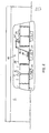
- Fig. 1 zeigt eine Draufsicht auf eine in einer Halle angeordnete Verrottungsanlage, das Hallendach abgenommen,
- Fig. 2 zeigt eine Längsansicht der Verrottungsanlage, die Hallenwand teilweise weggebrochen,
- Fig. 3 zeigt einen Querschnitt durch die Verrottungsanlage.
- In einer flachen Halle 1 sind durch Zwischenwände 2 oben offene, längliche Zellen 3 abgeteilt. Die Länge der Halle und die Zahl der Zellen werden im praktischen Falle wesentlich größer sein als in der zeichnerischen Darstellung.
- An den Schmalseiten der Zellen 3 entlang verläuft ein Gang 4. Von diesem aus sind die Zellen 3 durch Doppeltüren 5 auf ihrer ganzen Breite zugänglich. An den anderen Schmalseiten weisen die Zellen in der Hallenwand Türen 6 auf.
- In dem Gang 4 ist auf Schienen7 eine Verschiebebühne 8 mittels eines Antriebs 9 verfahrbar. Die Schienen 7 befinden sich in einem abgesenkten Teil 10 des Ganges 4, derart, daß die Oberseite der Verschiebebühne gleiche Höhe mit dem übrigen Teil 11 des Ganges hat. Dieser ist etwa so breit wie Flügel der Doppeltüren 5. Er weist an jeder Zelle das Ende eines in die Zelle und im wesentlichen auf deren ganzer Länge durch sie hindurchführenden Schienenpaares 12 auf, mit dem ein Schienenpaar 13 auf der Verschiebebühne 8 in Flucht gebracht werden kann. Auf den Schienenpaaren 12 und 13 ist eine weiter unten ausführlich beschriebene Umfüll-Einrichtung 14 verfahrbar.
- In die erste der Zellen 3 mündet durch die Hallenwand hindurch etwas über der Höhe der Zwischenwände 2 eine Materialzuführung 15. In seiner Betriebsstellung unter dieser und unmittelbar über der vorgesehenen Schütthöhe ist, an von der Hallendecke herab sich erstreckenden Hydraulikzylindern 16 hängend und mittels dieser auf- und abbeweglich, ein nicht näher dargestellter, jedoch an sich bekannter Kratzverteiler 17 angeordnet. Er läuft endlos um und schiebt das Material, das über die vorgesehene Schütthöhe hinaus aufgefüllt ist, jeweils bis dahin weiter, wo diese Höhe noch nicht erreicht ist; dort fällt es weiter ab.
- Die letzte Zelle 3 weist einen trichterförmig eingezogenen Boden 18 und an dessen Grund ein durch die Hallenwand aus der Zelle 3 herausführendes Förderband 19 auf.
- Zur Belüftung des Materials ist unter jeder Zelle 3 ein Belüftungskanal 20 angeordnet, der durch einen zwischen dem Schienenpaar 12 sich erstreckenden Rost 21 abgedeckt ist. Der Rost 21 kann, ebenso wie sonst der Boden und wie die Wände der Zellen und der Halle, aus Beton bestehen. Die Belüftungskanäle 20 sind aus einer gemeinsamen Luftzufuhrleitung 22 über Abzweigungen 23 mit Ventilatoren o. dgl. 24 jeweils einzeln beaufschlagt. Eine mit einem Ventilator 25 versehene, gemeinsame Abluftleitung 26 weist über den Zellen 3 Ansaugöffnungen 27 auf, die gleichfalls für jede Zelle einzeln einstellbar sein können.
- Die Umfüll-Einrichtung 14 weist an einem nicht gezeichneten Maschinenrahmen eine umlaufende Kratzkette 28 mit Stangen 29 auf, derenLänge gleich der Breite der Zellen 3 ist. Der vordere, auf das Material wirkende Trum der Kratzkette 28 läuft nach oben. Von ihm führen zwei zwischen den Trumen angeordnete Rutschen 30 und 31 rückwärts auf zwei kurze Förderbänder 32, die über einer weiteren Rutsche 33 zusammenlaufen, an die sich dann ein Förderband 34 anschließt. Das Förderband 34 läuft schräg nach oben über die Zwischenwand 2 hinweg und hat sein Abwurfende über der nächsten Zelle 3. Um das Material auch auf der Schräge zu halten, ist es mit geeigneten Mitnehmern versehen; die Schräge kann auch weniger steil eingerichtet werden als in der Zeichnung dargestellt. Unter dem Abwurfende des Förderbands 34 folgt noch einmal ein kurzes Förderband 35 derart, daß der Aufbau des Materials in der betreffenden Zelle mittels eines Kratzverteilers 36 vollständig bis zum Zellenende hin möglich ist, wenn die Kratzkette 28 am Ende der vorangegangenen Zelle anstößt.
- Darüber hinaus ist die Umfüll-Einrichtung 14 mit nicht gezeichneten Sprühdüsen zum Befeuchten des Materials während des Umfüllens versehen, um dem Material, das durch die Be-und Entlüftung getrocknet wird, die für den Verrottungsvorgang benötigte Feuchtigkeit zu geben. Es könnten aber auch andere Befeuchtungseinrichtungen installiert werden, z. B. über den Zellen.
- Schließlich ist eine nur in Fig. 3 dargestellte Wärmeisolierung 34 an den Wänden und der Decke der Halle zu nennen. Im Falle einer Anordnung der Zellen im Freien würde man die Zellen abdecken und ebenfalls an den Außenseiten so isolieren, daß die Verrottung in einer wärmeisolierten Baueinheit stattfindet.
- Die Arbeitsweise der Anlage ergibt sich im wesentlichen aus der vorstehenden Beschreibung.
- Bei einem Umfüllen in Abständen von zwei Tagen ist mit fünfzehn Zellen innerhalb eines Monats ein stabilisierter Kompost erreichbar.
Claims (11)
dadurch gekennzeichnet,
daß die Zellen (3) nebeneinander angeordnet sind.
dadurch gekennzeichnet,
daß die Zellen (3), vorzugsweise oben offen, in einer niedrigen Halle (1) angeordnet sind.
dadurch gekennzeichnet,
daß die Zellen (3), vorzugsweise in einer geraden Reihe, mit ihren Längsseiten aneinanderliegen und auf der einen Schmalseite von einem Gang (4) aus durch Türen (5) zugänglich sind, vorzugsweise auch auf der anderen Schmalseite, ggf. in der Hallenwand, Türen (6) aufweisen.
daß die Einrichtungen zum Belüften der Zellen (3) unter den Zellen angeordnete, durch Roste (21) abgedeckte Belüftungskanäle (2) aufweisen, vorzugsweise ferner über den Zellen jeweils Entlüftungen (27).
daß die Einrichtungen (14) zum Umfüllen des Materials im wesentlichen in einer entlang der Zellenreihe verfahrbaren und in die Zellen (3) einfahrbaren Einheit (14) zusammengefaßt sind, die vorzugsweise eine über die Zellenwand (2) hinweg zur nächsten Zelle (3) führende Fördereinrichtung (34) aufweist.
daß die genannte Einheit (14) entlang der Zellenreihe mittels einer Fahrbühne (8) verfahrbar und von dieser aus in die Zellen (3) einfahrbar ist, vorzugsweise auf Schienen (12), die vorzugsweise beiderseits der genannten Roste (21) verlaufen.
daß die genannte Einheit (14) ein Aufnahmegerät mit einer umlaufenden Kratzkette (28) aufweist, die der Materialfront einen nach oben laufenden Trum zukehrt, von dem mindestens eine Rutsche (30;31), ggf. auch weitere Fördermittel (32;33), zurück zu der genannten Fördereinrichtung (34) führt bzw. führen, vorzugsweise zu einem Förderband (39) oder einem pneumatischen Förderer.
daß unter dem Abwurfende der Fördereinrichtung (34) ein die Breite der nächsten Zelle (3) im wesentlichen überstreichender Kratzverteiler (36) an der Fördereinrichtung angeordnet ist.
daß in die erste der Zellen (3) eine Materialzuführung (15) mündet, vorzugsweise über einem die Fläche der Zelle (3) im wesentlichen überstreichenden, heb- und senkbaren Kratzverteiler (17).
daß die letzte Zelle (3) an ihrem, vorzugsweise trichterförmig eingezogenen, Boden (18) eine Austragseinrichtung (19) aufweist, vorzugsweise ein Förderband (19).
daß die Einrichtungen zum Umfüllen des Materials von Zelle zu Zelle mit Einrichtungen zum Befeuchten des Materials gekoppelt sind.
Priority Applications (1)
| Application Number | Priority Date | Filing Date | Title |
|---|---|---|---|
| AT82103538T ATE14715T1 (de) | 1981-05-02 | 1982-04-27 | Verrottungsanlage. |
Applications Claiming Priority (2)
| Application Number | Priority Date | Filing Date | Title |
|---|---|---|---|
| DE3117451A DE3117451C2 (de) | 1981-05-02 | 1981-05-02 | Verrottungsanlage |
| DE3117451 | 1981-05-02 |
Publications (2)
| Publication Number | Publication Date |
|---|---|
| EP0064257A1 true EP0064257A1 (de) | 1982-11-10 |
| EP0064257B1 EP0064257B1 (de) | 1985-08-07 |
Family
ID=6131333
Family Applications (1)
| Application Number | Title | Priority Date | Filing Date |
|---|---|---|---|
| EP19820103538 Expired EP0064257B1 (de) | 1981-05-02 | 1982-04-27 | Verrottungsanlage |
Country Status (4)
| Country | Link |
|---|---|
| US (1) | US4433055A (de) |
| EP (1) | EP0064257B1 (de) |
| AT (1) | ATE14715T1 (de) |
| DE (1) | DE3117451C2 (de) |
Cited By (4)
| Publication number | Priority date | Publication date | Assignee | Title |
|---|---|---|---|---|
| EP0241802A3 (de) * | 1986-04-02 | 1988-09-21 | Otto Nockemann | Verrottungs- und Wärmegewinnungsanlage für organische Abfallprodukte |
| EP0621248A1 (de) * | 1993-04-21 | 1994-10-26 | Vogel, Werner Ing. | Einrichtung zum Kompostieren von organischen Abfällen |
| FR2762597A1 (fr) * | 1997-04-29 | 1998-10-30 | Ass Les Mouettes | Procede de compostage a partir d'un courant de matiere premiere liquide comprenant du lisier de porc et installation pour la mise en oeuvre dudit procede |
| FR3003253A1 (fr) * | 2013-03-14 | 2014-09-19 | Faltazi | Composteur a plusieurs compartiments |
Families Citing this family (9)
| Publication number | Priority date | Publication date | Assignee | Title |
|---|---|---|---|---|
| US4578189A (en) * | 1984-08-24 | 1986-03-25 | Stetter Gmbh | Sludge settling plant |
| DE3517523C1 (de) * | 1985-05-15 | 1986-12-04 | Manfred 7250 Leonberg Betz | Komposter |
| EP0211109A1 (de) * | 1985-08-05 | 1987-02-25 | ABAY Engineering S.A. | Gärungstroganlage mit kontinuierlichem Betrieb |
| DE3735362C2 (de) * | 1987-10-19 | 1997-06-19 | Werner Buerklin | Verfahren zum Kompostieren von Abfall und Vorrichtung zum Herstellen einer Schichtrotte |
| AT398758B (de) * | 1992-07-30 | 1995-01-25 | Josef F Ortner | Transportable vorrichtung zum kompostieren von vegetabilen abfällen |
| DE59306649D1 (de) * | 1992-10-05 | 1997-07-10 | Rindelaub Frank Alex Erich | Kompostieranlage |
| DE4418409C1 (de) * | 1994-05-26 | 1995-08-17 | Metallgesellschaft Ag | Rechnergesteuerte Absaugvorrichtung für Rottehallen |
| CA2472943A1 (fr) * | 2004-07-09 | 2006-01-09 | Maurice Labbe | Systeme et procede de compostage |
| US10864610B2 (en) * | 2019-03-21 | 2020-12-15 | Dadco, Inc. | Swarf container filler and method |
Citations (10)
| Publication number | Priority date | Publication date | Assignee | Title |
|---|---|---|---|---|
| BE413106A (de) * | ||||
| FR762468A (de) * | 1934-04-11 | |||
| FR1354143A (fr) * | 1962-11-22 | 1964-03-06 | Ile D Etudes Biolog Appliquees | Dispositif et machine pour le traitement, la manipulation et la fermentation aérobie des déchets urbains |
| FR85086E (fr) * | 1964-01-13 | 1965-06-04 | Traitement Ind Des Gadoues Soc | Procédé de transformation en compost de déchets organiques, notamment immondices, boues de curage et matières analogues |
| GB1083611A (en) * | 1963-03-04 | 1967-09-20 | Hydraulic Developments Ltd | Improvements in and relating to fertilizers and agricultural stock feed |
| FR1527822A (fr) * | 1967-02-16 | 1968-06-07 | Venot Pic Sa | Dispositif pour le traitement des ordures ménagères |
| FR1544063A (fr) * | 1967-03-14 | 1968-10-31 | Buehler Ag Geb | Procédé et installation de retournement de meules de compost |
| US3856276A (en) * | 1972-09-08 | 1974-12-24 | R Pannell | Compost processing machine |
| US3881707A (en) * | 1972-04-05 | 1975-05-06 | Louis R Toto | Scoop means and arrangements thereof for vehicular composting machine |
| DE2917048A1 (de) * | 1979-04-27 | 1980-11-06 | Zueblin Ag | Vorrichtung zur mietenkompostierung |
Family Cites Families (7)
| Publication number | Priority date | Publication date | Assignee | Title |
|---|---|---|---|---|
| DE1237593B (de) * | 1960-10-14 | 1967-03-30 | Prep Ind Combustibles | Vorrichtung zur aeroben Vergaerung vergaerbarer Stoffe zu Kompost oder Humusduengemitteln |
| US3438740A (en) * | 1966-02-01 | 1969-04-15 | New Life Foundation | Composting conveyor |
| CH563946A5 (de) * | 1971-07-30 | 1975-07-15 | Kaelin J R | |
| ZA743720B (en) * | 1973-07-11 | 1975-08-27 | Ohio Feed Lot | Process for aerobic thermophilic decomposition of organic waste |
| DE2451284C3 (de) * | 1974-10-29 | 1985-11-14 | Heidelberger Zement Ag, 6900 Heidelberg | Verfahren zur raschen Ersetzung der gesamten Luft im Rottegut durch Frischluft bei der aeroben Verrottung und Entseuchung von Kompostrohgut und/oder Klärschlamm in mindestens einem Behälter mit luftdichten Wänden |
| US4108609A (en) * | 1977-08-04 | 1978-08-22 | Petzinger Manfred Wilhelm Augu | Compost container |
| US4326874A (en) * | 1978-03-13 | 1982-04-27 | Buerklin Werner | Process and apparatus for preparing compostable material |
-
1981
- 1981-05-02 DE DE3117451A patent/DE3117451C2/de not_active Expired
-
1982
- 1982-04-27 AT AT82103538T patent/ATE14715T1/de not_active IP Right Cessation
- 1982-04-27 EP EP19820103538 patent/EP0064257B1/de not_active Expired
- 1982-04-29 US US06/373,124 patent/US4433055A/en not_active Expired - Fee Related
Patent Citations (10)
| Publication number | Priority date | Publication date | Assignee | Title |
|---|---|---|---|---|
| BE413106A (de) * | ||||
| FR762468A (de) * | 1934-04-11 | |||
| FR1354143A (fr) * | 1962-11-22 | 1964-03-06 | Ile D Etudes Biolog Appliquees | Dispositif et machine pour le traitement, la manipulation et la fermentation aérobie des déchets urbains |
| GB1083611A (en) * | 1963-03-04 | 1967-09-20 | Hydraulic Developments Ltd | Improvements in and relating to fertilizers and agricultural stock feed |
| FR85086E (fr) * | 1964-01-13 | 1965-06-04 | Traitement Ind Des Gadoues Soc | Procédé de transformation en compost de déchets organiques, notamment immondices, boues de curage et matières analogues |
| FR1527822A (fr) * | 1967-02-16 | 1968-06-07 | Venot Pic Sa | Dispositif pour le traitement des ordures ménagères |
| FR1544063A (fr) * | 1967-03-14 | 1968-10-31 | Buehler Ag Geb | Procédé et installation de retournement de meules de compost |
| US3881707A (en) * | 1972-04-05 | 1975-05-06 | Louis R Toto | Scoop means and arrangements thereof for vehicular composting machine |
| US3856276A (en) * | 1972-09-08 | 1974-12-24 | R Pannell | Compost processing machine |
| DE2917048A1 (de) * | 1979-04-27 | 1980-11-06 | Zueblin Ag | Vorrichtung zur mietenkompostierung |
Cited By (4)
| Publication number | Priority date | Publication date | Assignee | Title |
|---|---|---|---|---|
| EP0241802A3 (de) * | 1986-04-02 | 1988-09-21 | Otto Nockemann | Verrottungs- und Wärmegewinnungsanlage für organische Abfallprodukte |
| EP0621248A1 (de) * | 1993-04-21 | 1994-10-26 | Vogel, Werner Ing. | Einrichtung zum Kompostieren von organischen Abfällen |
| FR2762597A1 (fr) * | 1997-04-29 | 1998-10-30 | Ass Les Mouettes | Procede de compostage a partir d'un courant de matiere premiere liquide comprenant du lisier de porc et installation pour la mise en oeuvre dudit procede |
| FR3003253A1 (fr) * | 2013-03-14 | 2014-09-19 | Faltazi | Composteur a plusieurs compartiments |
Also Published As
| Publication number | Publication date |
|---|---|
| EP0064257B1 (de) | 1985-08-07 |
| US4433055A (en) | 1984-02-21 |
| DE3117451A1 (de) | 1982-11-18 |
| DE3117451C2 (de) | 1987-01-02 |
| ATE14715T1 (de) | 1985-08-15 |
Similar Documents
| Publication | Publication Date | Title |
|---|---|---|
| EP0064257B1 (de) | Verrottungsanlage | |
| DE69315446T2 (de) | Kontinuierliche kompostvorrichtung | |
| DE3020011C2 (de) | ||
| EP0004094A2 (de) | Vorrichtung zum Aufbereiten von kompostierfähigem Material | |
| EP0232700B1 (de) | Anlage zur Herstellung von Kompost aus organischen Abfallstoffen | |
| DE8704843U1 (de) | Einrichtung zum Umsetzen von Müll auf einem Kompostierfeld | |
| DE3934379C1 (de) | ||
| EP0523009B1 (de) | Kompostieranlage | |
| EP0710636A1 (de) | Einrichtung zum Komposieren von organischen Abfällen | |
| DE69307550T2 (de) | Vorrichtung für vorübergehende lagerung von schüttgütern | |
| DE69919886T2 (de) | Vorrichtung zum drehen und/oder mischen eines flachbett komposts | |
| EP0011103A2 (de) | Verfahren und Anlage zur Herstellung von Kompostmaterial durch aerobe Behandlung und Entseuchung von gemischten Siedlungsabfällen | |
| EP0234337A2 (de) | Zerkleinerungsvorrichtung für Abfall | |
| DE3004016C2 (de) | ||
| DE202017104385U1 (de) | Transportabler Kompostierungs-Container, modulare Kompostierungs-Anlage | |
| DE4328052A1 (de) | Verfahren und Vorrichtung zur Kompostierung von Rottegut | |
| DE19628414A1 (de) | Für ortsfesten oder transportablen Einsatz verwendbare Komponente zum Biorecycling von Stoffen | |
| DE1592781B2 (de) | Anlage fuer die fermentative kompostierung von stadtmuell | |
| DE1642674C3 (de) | Keimkastenanlage mit mehreren nebeneinander verlegten Keimkästen | |
| WO1989000551A1 (fr) | Installation de decomposition par putrefaction | |
| EP0106259A2 (de) | Wärmerückgewinnungsanlage für ein Gebäude | |
| DE9416478U1 (de) | Vorrichtung zum Verteilen von Mulch im Gelände | |
| DE1592781C3 (de) | Anlage für die fermentative Kompostierung von Stadtmüll | |
| EP0485358A1 (de) | Kompostiervorrichtung | |
| DE29623667U1 (de) | Für ortsfesten oder transportablen Einsatz verwendbare Komponente zum Biorecycling von Stoffen |
Legal Events
| Date | Code | Title | Description |
|---|---|---|---|
| PUAI | Public reference made under article 153(3) epc to a published international application that has entered the european phase |
Free format text: ORIGINAL CODE: 0009012 |
|
| AK | Designated contracting states |
Designated state(s): AT BE CH FR GB IT NL SE |
|
| 17P | Request for examination filed |
Effective date: 19821005 |
|
| ITF | It: translation for a ep patent filed | ||
| GRAA | (expected) grant |
Free format text: ORIGINAL CODE: 0009210 |
|
| AK | Designated contracting states |
Designated state(s): AT BE CH FR GB IT LI NL SE |
|
| PG25 | Lapsed in a contracting state [announced via postgrant information from national office to epo] |
Ref country code: NL Effective date: 19850807 Ref country code: BE Effective date: 19850807 |
|
| REF | Corresponds to: |
Ref document number: 14715 Country of ref document: AT Date of ref document: 19850815 Kind code of ref document: T |
|
| PG25 | Lapsed in a contracting state [announced via postgrant information from national office to epo] |
Ref country code: SE Effective date: 19850830 |
|
| ET | Fr: translation filed | ||
| NLV1 | Nl: lapsed or annulled due to failure to fulfill the requirements of art. 29p and 29m of the patents act | ||
| PG25 | Lapsed in a contracting state [announced via postgrant information from national office to epo] |
Ref country code: AT Effective date: 19860427 |
|
| PLBE | No opposition filed within time limit |
Free format text: ORIGINAL CODE: 0009261 |
|
| STAA | Information on the status of an ep patent application or granted ep patent |
Free format text: STATUS: NO OPPOSITION FILED WITHIN TIME LIMIT |
|
| 26N | No opposition filed | ||
| GBPC | Gb: european patent ceased through non-payment of renewal fee | ||
| PG25 | Lapsed in a contracting state [announced via postgrant information from national office to epo] |
Ref country code: GB Effective date: 19881121 |
|
| ITTA | It: last paid annual fee | ||
| PGFP | Annual fee paid to national office [announced via postgrant information from national office to epo] |
Ref country code: CH Payment date: 20000412 Year of fee payment: 19 |
|
| PGFP | Annual fee paid to national office [announced via postgrant information from national office to epo] |
Ref country code: FR Payment date: 20000413 Year of fee payment: 19 |
|
| PG25 | Lapsed in a contracting state [announced via postgrant information from national office to epo] |
Ref country code: FR Free format text: THE PATENT HAS BEEN ANNULLED BY A DECISION OF A NATIONAL AUTHORITY Effective date: 20010430 |
|
| PG25 | Lapsed in a contracting state [announced via postgrant information from national office to epo] |
Ref country code: LI Free format text: LAPSE BECAUSE OF NON-PAYMENT OF DUE FEES Effective date: 20010526 Ref country code: CH Free format text: LAPSE BECAUSE OF NON-PAYMENT OF DUE FEES Effective date: 20010526 |
|
| REG | Reference to a national code |
Ref country code: CH Ref legal event code: PL |
|
| REG | Reference to a national code |
Ref country code: FR Ref legal event code: ST |