EP0064628A1 - Einrichtung zur Notstoppung von Polymerisationsansätzen - Google Patents
Einrichtung zur Notstoppung von Polymerisationsansätzen Download PDFInfo
- Publication number
- EP0064628A1 EP0064628A1 EP82103360A EP82103360A EP0064628A1 EP 0064628 A1 EP0064628 A1 EP 0064628A1 EP 82103360 A EP82103360 A EP 82103360A EP 82103360 A EP82103360 A EP 82103360A EP 0064628 A1 EP0064628 A1 EP 0064628A1
- Authority
- EP
- European Patent Office
- Prior art keywords
- compressed gas
- rupture disc
- line
- reaction
- emergency
- Prior art date
- Legal status (The legal status is an assumption and is not a legal conclusion. Google has not performed a legal analysis and makes no representation as to the accuracy of the status listed.)
- Granted
Links
- 238000006116 polymerization reaction Methods 0.000 title claims abstract description 16
- 239000003112 inhibitor Substances 0.000 claims abstract description 9
- 238000006243 chemical reaction Methods 0.000 claims description 25
- OKTJSMMVPCPJKN-UHFFFAOYSA-N Carbon Chemical compound [C] OKTJSMMVPCPJKN-UHFFFAOYSA-N 0.000 claims description 2
- 229910002804 graphite Inorganic materials 0.000 claims description 2
- 239000010439 graphite Substances 0.000 claims description 2
- 239000002184 metal Substances 0.000 claims description 2
- 230000009172 bursting Effects 0.000 abstract description 4
- 239000007789 gas Substances 0.000 description 15
- IJGRMHOSHXDMSA-UHFFFAOYSA-N Atomic nitrogen Chemical compound N#N IJGRMHOSHXDMSA-UHFFFAOYSA-N 0.000 description 4
- BZHJMEDXRYGGRV-UHFFFAOYSA-N Vinyl chloride Chemical compound ClC=C BZHJMEDXRYGGRV-UHFFFAOYSA-N 0.000 description 4
- 238000001816 cooling Methods 0.000 description 4
- 239000000498 cooling water Substances 0.000 description 3
- 229920000642 polymer Polymers 0.000 description 3
- 239000000243 solution Substances 0.000 description 3
- XLYOFNOQVPJJNP-UHFFFAOYSA-N water Chemical compound O XLYOFNOQVPJJNP-UHFFFAOYSA-N 0.000 description 3
- QIGBRXMKCJKVMJ-UHFFFAOYSA-N Hydroquinone Chemical compound OC1=CC=C(O)C=C1 QIGBRXMKCJKVMJ-UHFFFAOYSA-N 0.000 description 2
- PPBRXRYQALVLMV-UHFFFAOYSA-N Styrene Chemical compound C=CC1=CC=CC=C1 PPBRXRYQALVLMV-UHFFFAOYSA-N 0.000 description 2
- 239000000178 monomer Substances 0.000 description 2
- 229910052757 nitrogen Inorganic materials 0.000 description 2
- 239000011541 reaction mixture Substances 0.000 description 2
- 238000003756 stirring Methods 0.000 description 2
- 239000000126 substance Substances 0.000 description 2
- BJEMXPVDXFSROA-UHFFFAOYSA-N 3-butylbenzene-1,2-diol Chemical compound CCCCC1=CC=CC(O)=C1O BJEMXPVDXFSROA-UHFFFAOYSA-N 0.000 description 1
- UFHFLCQGNIYNRP-UHFFFAOYSA-N Hydrogen Chemical compound [H][H] UFHFLCQGNIYNRP-UHFFFAOYSA-N 0.000 description 1
- 239000012267 brine Substances 0.000 description 1
- 238000003889 chemical engineering Methods 0.000 description 1
- 230000007613 environmental effect Effects 0.000 description 1
- -1 ethylhexyl Chemical group 0.000 description 1
- 239000001257 hydrogen Substances 0.000 description 1
- 229910052739 hydrogen Inorganic materials 0.000 description 1
- 230000001771 impaired effect Effects 0.000 description 1
- 229910052756 noble gas Inorganic materials 0.000 description 1
- 150000002835 noble gases Chemical class 0.000 description 1
- 229920002689 polyvinyl acetate Polymers 0.000 description 1
- 239000011118 polyvinyl acetate Substances 0.000 description 1
- 238000010992 reflux Methods 0.000 description 1
- 230000002040 relaxant effect Effects 0.000 description 1
- HPALAKNZSZLMCH-UHFFFAOYSA-M sodium;chloride;hydrate Chemical compound O.[Na+].[Cl-] HPALAKNZSZLMCH-UHFFFAOYSA-M 0.000 description 1
Images
Classifications
-
- B—PERFORMING OPERATIONS; TRANSPORTING
- B01—PHYSICAL OR CHEMICAL PROCESSES OR APPARATUS IN GENERAL
- B01J—CHEMICAL OR PHYSICAL PROCESSES, e.g. CATALYSIS OR COLLOID CHEMISTRY; THEIR RELEVANT APPARATUS
- B01J19/00—Chemical, physical or physico-chemical processes in general; Their relevant apparatus
- B01J19/0006—Controlling or regulating processes
- B01J19/002—Avoiding undesirable reactions or side-effects, e.g. avoiding explosions, or improving the yield by suppressing side-reactions
-
- B—PERFORMING OPERATIONS; TRANSPORTING
- B01—PHYSICAL OR CHEMICAL PROCESSES OR APPARATUS IN GENERAL
- B01J—CHEMICAL OR PHYSICAL PROCESSES, e.g. CATALYSIS OR COLLOID CHEMISTRY; THEIR RELEVANT APPARATUS
- B01J2219/00—Chemical, physical or physico-chemical processes in general; Their relevant apparatus
- B01J2219/00049—Controlling or regulating processes
- B01J2219/00245—Avoiding undesirable reactions or side-effects
- B01J2219/00272—Addition of reaction inhibitor
Definitions
- the present invention relates to a device for emergency stopping of polymerization reactions in closed reaction containers.
- the polymerization of monomers such as styrene or vinyl chloride is carried out batchwise in reaction vessels provided with a stirrer with a capacity of up to 200 m 3 .
- the heat released in the exothermic polymerization reactions is removed after the monomer-specific reaction temperature has been reached with the aid of cooling water or cooling brine, which are pumped through the cooling jacket of the reaction container and through a reflux condenser which may be arranged on the reaction container. If the cooling fails during the polymerization of a batch, there is an uncontrolled rise in temperature and pressure in the reaction vessel.
- Hydroquinone or butyl catechol for example, are known as chemicals which bring the polymerization reactions to a standstill in small amounts, so-called inhibitors.
- a disadvantage of the known emergency stop device is that the bottom valves can be blocked or caked mechanically by caking polymer or that the bottom valves, which must be remotely controlled for safety reasons, cannot be operated in the event of a power failure.
- a rupture disc is inserted into an opening in the bottom of the reaction container; that the outer edge of the rupture disc and the lower flange of an angled line for receiving inhibitor solution touch each other and are tightly fastened to the outside of the polymerization vessel; and that the upper flange of the line is connected to a compressed gas line which is connected to a compressed gas source.
- valves are required which can be impaired in their functionality by polymer caking or sticking.
- pressurized gas bottles in the device according to the invention is advantageous because they can also function in the event of faults in the pressurized gas network.
- the pressure rise caused by the compressed gas in the reaction vessel can be limited so that the safety valve on the reaction vessel does not respond when the emergency stop is stopped.
- an optimal distribution of the inhibitor in the polymerization batch is given even in the event of a stirrer failure due to the extremely high rate of entry of the inhibitor and the gas flowing into the reaction vessel.
- nitrogen, hydrogen or noble gases can be used as pressurized gases.
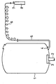
- a reaction container 1 The bottom of a reaction container 1 is penetrated in the middle by a stirring shaft 2 of a stirrer 3 driven from below.
- a metallic rupture disc 4 is inserted into the side opening in the bottom of the reaction container 1.
- a compressed gas line 6 opens into the other end of the line 5 and is connected to the valve 7 of a compressed gas bottle 8 filled with nitrogen.
- the cooling was used to simulate a cooling water failure. Water supply interrupted. Within 5 minutes, the temperature in reaction vessel 1 rose by 5 ° C. and the pressure by 1 bar. Now the valve 7 of the compressed gas bottle 8 (content: 3 1, pressure: 200 bar) was fully opened. The pressure building up in line 5 and in the compressed gas line 6 tore the rupture disk 4 at 40 bar, so that the inhibitor solution entered the reaction mixture at high speed and mixed with it. The rise in pressure and temperature in reaction vessel 1 came to a standstill immediately thereafter.
Landscapes
- Chemical & Material Sciences (AREA)
- Organic Chemistry (AREA)
- Chemical Kinetics & Catalysis (AREA)
- Polymerisation Methods In General (AREA)
- Physical Or Chemical Processes And Apparatus (AREA)
- Pinball Game Machines (AREA)
- Circuit Arrangements For Discharge Lamps (AREA)
- Organic Low-Molecular-Weight Compounds And Preparation Thereof (AREA)
Abstract
Description
- Die vorliegende Erfindung betrifft eine Einrichtung zur Notstoppung von Polymerisationsreaktionen in geschlossenen Reaktionsbehältern.
- Die Polymerisation von Monomeren wie beispielsweise Styrol oder Vinylchlorid wird diskontinuierlich in mit einem Rührer versehenen Reaktionsbehältern mit einem Fassungsvermögen bis zu 200 m3 durchgeführt. Die bei den exothermen Polymerisationsreaktionen freiwerdende Wärme wird, nachdem die monomerenspezifische Reaktionstemperatur erreicht ist, mit Hilfe von Kühlwasser oder Kühlsole abgeführt, welche durch den Kühlmantel des Reaktionsbehälters und durch einen gegebenenfalls auf dem Reaktionsbehälter angeordneten Rückflußkühler gepumpt werden. Fällt die Kühlung während der Polymerisation einer Charge aus, so kommt es zu einem unkontollierten Temperatur- und Druckanstieg im Reaktionsbehälter.
- Um ein Zerbersten des Reaktionsbehälters in einem solchen Falle zu vermeiden, ist es bekannt, neben der Ausrüstung des Reaktionsbehälters mit einem in die Atmosphäre oder in eine Fackel entspannenden Sicherheitsventil zwei weitere Sicherheitssysteme vorzusehen; und zwar die Notentspannung und die Notstoppung. Während die Apparatur für die Notentspannung sorgfältig auf die Reaktionsdynamik abgestimmt sein muß und umfangreiche regeltechnische Einrichtungen erfordert, ist als letzte Maßnahme vor der aus Umweltschutzgründen unerwünschten Entspannung durch das Sicherheitsventil die Notstoppung möglich. Hierbei wird eine Chemikalie durch Bodenventile in den Reaktionsbehälter eingedrückt und untergemischt, wodurch die Polymerisationsreaktion augenblicklich unterbrochen wird (vergl. "Chemie-Technik", 5 (1976) Seiten 137 und 138).
- Als Chemikalien, welche die Polymerisationsreaktionen schon in kleinen Mengen zum Erliegen bringen, sog. Inhibitoren, sind beispielsweise Hydrochinon oder Butylbrenzkatechin bekannt.
- Nachteilig ist bei der bekannten Einrichtung zur Notstoppung, daß die Bodenventile durch anbackendes Polymerisat blockiert oder mechanisch gehemmt sein können oder daß die Bodenventile, welche aus Sicherheitsgründen fernsteuerbar sein müssen, bei Energieausfall nicht betätigbar sind.
- Es ist daher Aufgabe der vorliegenden Erfindung, eine Einrichtung zur Notstoppung von Polymerisationsreaktionen in geschlossenen Reaktionsbehältern anzugeben, deren Funktionsfähigkeit unabhängig von Polymerisatanbackungen und Ausfall der Netzenergien gewährleistet ist.
- Das wird erfindungsgemäß dadurch erreicht, daß in eine Öffnung im Boden des Reaktionsbehälters eine Berstscheibe eingesetzt ist; daß der äußere Rand der Berstscheibe und der untere Flansch einer abgewinkelten Leitung zur Aufnahme von Inhibitorlösung einander berühren und dichtschließend an der Außenseite des Polymerisationskessels befestigt sind; und daß der obere Flansch der Leitung mit einer Druckgas-Leitung verbunden ist, welche an eine Druckgas-Quelle angeschlossen ist.
- Die Einrichtung gemäß der Erfindung kann wahlweise auch noch dadurch weitergebildet sein, daß
- a) die Berstscheibe innenbündig eingesetzt ist,
- b) die Berstscheibe aus Metall besteht
- c) die Berstscheibe aus Graphit besteht,
- d) die Berstscheibe einem Druck von mindestens 25 bar standhält,
- e) die Druckgas-Leitung an das Ventil einer Druckgas-Flasche angeschlossen ist.
- Bei der erfindungsgemäßen Einrichtung sind keine Ventile erforderlich, welche durch Polymerisatanbackung oder Festsitzen in ihrer Funktionsfähigkeit gestört sein können.
- Am Reaktionsbehälter sind zur Aufnahme der Einrichtung gemäß der Erfindung keine Stutzen erforderlich, welche zupolymerisieren können.
- Bei der erfindungsgemäßen Einrichtung sind keine Manipulationen in der Nähe des kritischen Reaktionsbehälters notwendig, weil die Druckgas-Quelle weit entfernt davon, beispielsweise in der Meßwarte, geöffnet werden kann.
- Vorteilhaft ist die Verwendung von Druckgas-Flaschen bei der Einrichtung gemäß der Erfindung, weil diese auch bei Störungen im Druckgasnetz funktionsfähig sind. Dabei kann durch entsprechende Wahl von Volumen der Druckgas-Flasche und des in ihr herrschenden Druckes der durch das Druckgas im Reaktionsbehälter bewirkte Druckanstieg begrenzt werden, so daß das Sicherheitsventil am Reaktionsbehälter bei der Notstoppung nicht anspricht.
- Bei der erfindungsgemäßen Einrichtung ist eine optimale Verteilung des Inhibitors im Polymerisationsansatz auch bei Rührerausfall durch die extrem hohe Eintrittsgeschwindigkeit des Inhibitors und des nachströmenden Gases in den Reaktionsbehälter gegeben.
- Bei der erfindungsgemäßen Einrichtung können als Druckgase Stickstoff, Wasserstoff oder Edelgase verwendet werden.
- In der beigefügten Zeichnung ist ein Ausführungsbeispiel des Gegenstandes der Erfindung schematisch dargestellt.
- Der Boden eines Reaktionsbehälters 1 ist mittig von einer Rührwelle 2 eines von unten angetriebenen Rührers 3 durchdrungen. In eine. seitliche Öffnung im Boden des Reaktionsbehälters 1 ist eine metallische Berstscheibe 4 eingesetzt. Auf der Außenseite des Polymerisationskessels 1 schließt sich an die Berstscheibe 4 das eine Ende einer abgewinkelten Leitung 5 an, welche mit Inhibitorlösung gefüllt ist. In das andere Ende der Leitung 5 mündet eine Druckgas-Leitung 6 ein, welche an das Ventil 7 einer mit Stickstoff gefüllten Druckgas-Flasche 8 angeschlossen ist.
- Die Funktionsweise der erfindungsgemäßen Einrichtung sei nunmehr am Beispiel der Polymerisation von Vinylchlorid erläutert.
- In den Reaktionsbehälter 1 (25 m3) wurden
- 14 m3 Wasser
- 9 m3 Vinylchlorid
- 8 kg teilverseiftes Polyvinylaccetat und
- 5 kg Ethylhexylperoxidikarbonat
- Zur Simulierung eines Kühlwasserausfalles wurde die Kühl-. wasserzuführ unterbrochen. Innerhalb von 5 Minuten stieg im Reaktionsbehälter 1 die Temperatur um 5°C und der Druck um 1 bar an. Nun wurde das Ventil 7 der Druckgas-Flasche 8 (Inhalt: 3 1, Druck: 200 bar) voll geöffnet. Der sich in der Leitung 5 und in der Druckgas-Leitung 6 aufbauende Druck zerriß die Berstscheibe 4 bei 40 bar, so daß die Inhibitorlösung mit großer Geschwindigkeit in die Reaktionsmischung eintrat und sich mit ihr vermischte. Der Druck- und Temperaturanstieg im Reaktionsbehälter 1 kam unmittelbar darauf zum Stillstand.
eingetragen und die Reaktionsmischung unter Rühren auf 55° erhitzt. Nach Einsetzen der Polymerisationsreaktion wurde die Temperatur von 55°C durch Durchleiten von Kühlwasser durch den Doppelmantel des Reaktionsbehälters 1 aufrechterhalten.
Claims (6)
Priority Applications (1)
| Application Number | Priority Date | Filing Date | Title |
|---|---|---|---|
| AT82103360T ATE15054T1 (de) | 1981-05-11 | 1982-04-21 | Einrichtung zur notstoppung von polymerisationsansaetzen. |
Applications Claiming Priority (2)
| Application Number | Priority Date | Filing Date | Title |
|---|---|---|---|
| DE3118603 | 1981-05-11 | ||
| DE19813118603 DE3118603A1 (de) | 1981-05-11 | 1981-05-11 | Einrichtung zur notstoppung von polymerisationsreaktionen |
Publications (2)
| Publication Number | Publication Date |
|---|---|
| EP0064628A1 true EP0064628A1 (de) | 1982-11-17 |
| EP0064628B1 EP0064628B1 (de) | 1985-08-21 |
Family
ID=6131978
Family Applications (1)
| Application Number | Title | Priority Date | Filing Date |
|---|---|---|---|
| EP82103360A Expired EP0064628B1 (de) | 1981-05-11 | 1982-04-21 | Einrichtung zur Notstoppung von Polymerisationsansätzen |
Country Status (3)
| Country | Link |
|---|---|
| EP (1) | EP0064628B1 (de) |
| AT (1) | ATE15054T1 (de) |
| DE (2) | DE3118603A1 (de) |
Cited By (3)
| Publication number | Priority date | Publication date | Assignee | Title |
|---|---|---|---|---|
| USH1957H1 (en) | 1997-10-29 | 2001-04-03 | Basf Aktiengesellschaft | Immediate termination of free radical polymerizations |
| US6315012B1 (en) | 1997-11-11 | 2001-11-13 | Basf Aktiengesellschaft | Device for feeding a fluid into a container |
| US6517057B1 (en) | 1998-05-19 | 2003-02-11 | Basf Aktiengesellschaft | Supply system for transferring a fluid to a container |
Families Citing this family (3)
| Publication number | Priority date | Publication date | Assignee | Title |
|---|---|---|---|---|
| DE4018232A1 (de) * | 1990-06-07 | 1991-12-12 | Beiersdorf Ag | Regelung der polymerisation mit einem gefluteten kondensator |
| DE19948630A1 (de) * | 1999-10-08 | 2001-05-03 | Steag Micro Tech Gmbh | Verfahren und Vorrichtung zum Behandeln von Substraten |
| DE102013007298A1 (de) * | 2013-04-26 | 2014-10-30 | Basf Se | Verfahren und Versorgungseinheit zur Restabilisierung von radikalisch polymerisierbaren Monomeren |
Citations (2)
| Publication number | Priority date | Publication date | Assignee | Title |
|---|---|---|---|---|
| FR2116147A5 (de) * | 1970-11-27 | 1972-07-07 | Stamicarbon | |
| DE2428705B1 (de) * | 1974-06-14 | 1975-11-13 | Chemische Werke Huels Ag, 4370 Marl | Vorrichtung zum Abfangen durchgehender exothermer Reaktionen |
-
1981
- 1981-05-11 DE DE19813118603 patent/DE3118603A1/de not_active Withdrawn
-
1982
- 1982-04-21 DE DE8282103360T patent/DE3265558D1/de not_active Expired
- 1982-04-21 AT AT82103360T patent/ATE15054T1/de not_active IP Right Cessation
- 1982-04-21 EP EP82103360A patent/EP0064628B1/de not_active Expired
Patent Citations (2)
| Publication number | Priority date | Publication date | Assignee | Title |
|---|---|---|---|---|
| FR2116147A5 (de) * | 1970-11-27 | 1972-07-07 | Stamicarbon | |
| DE2428705B1 (de) * | 1974-06-14 | 1975-11-13 | Chemische Werke Huels Ag, 4370 Marl | Vorrichtung zum Abfangen durchgehender exothermer Reaktionen |
Cited By (3)
| Publication number | Priority date | Publication date | Assignee | Title |
|---|---|---|---|---|
| USH1957H1 (en) | 1997-10-29 | 2001-04-03 | Basf Aktiengesellschaft | Immediate termination of free radical polymerizations |
| US6315012B1 (en) | 1997-11-11 | 2001-11-13 | Basf Aktiengesellschaft | Device for feeding a fluid into a container |
| US6517057B1 (en) | 1998-05-19 | 2003-02-11 | Basf Aktiengesellschaft | Supply system for transferring a fluid to a container |
Also Published As
| Publication number | Publication date |
|---|---|
| EP0064628B1 (de) | 1985-08-21 |
| DE3118603A1 (de) | 1982-11-25 |
| DE3265558D1 (en) | 1985-09-26 |
| ATE15054T1 (de) | 1985-09-15 |
Similar Documents
| Publication | Publication Date | Title |
|---|---|---|
| DE2537126C2 (de) | Einrichtung zur Umsetzung von Ozon oder einem ozonhaltigen Gas mit einer Flüssigkeit | |
| EP0064628B1 (de) | Einrichtung zur Notstoppung von Polymerisationsansätzen | |
| EP0354359A1 (de) | Spülblock | |
| EP1082171B1 (de) | System für die einführung einer flüssigkeit in ein behälter | |
| EP1028803B1 (de) | Vorrichtung zum einbringen eines fluids in einen behälter | |
| DE69207569T2 (de) | Gaslieferungstafeln | |
| JP2535040B2 (ja) | 高圧重合反応器の放圧工程における炭化水素放出の減少法 | |
| EP2988860B1 (de) | Verfahren und versorgungseinheit zur restabilisierung von radikalisch polymerisierbaren monomeren | |
| DE60011982T2 (de) | Probenentnahmesystem für Wirbelschicht-Gasphasenpolymerisationsverfahren | |
| DE3850755T2 (de) | Gasturbinenanlage mit Druckstabilisator für Notfälle. | |
| WO2002064454A2 (de) | Sicherheitsbehälteranordnung zur aufnahme gefährlicher flüssigkeiten, insbesondere eines organischen peroxids | |
| EP3912688A1 (de) | Sichere inertisierungsvorrichtung | |
| EP0978310A2 (de) | Verfahren zum Dosieren eines flüssigen, gasförmigen oder in überkritischem Zustand vorliegenden Mediums in einen Druckreaktor | |
| EP0774278B1 (de) | Feuerlöschanlage | |
| DE19959834C1 (de) | Verfahren und Einrichtung zur Notkühlung und Druckentlastung einer Anlage für exotherme Prozesse | |
| DD264151A5 (de) | Abcheidesystem fuer rohrenreaktoren oder autoklaven | |
| DE2825851B1 (de) | Vorrichtung zur Versorgung von Duesen mit gasfoermigen und/oder fluessigen Kohlenwasserstoffen | |
| EP4493510B1 (de) | Verfahren zur kontinuierlichen wasserstofferzeugung durch magnesiumhaltige basismaterialien | |
| EP0681866B1 (de) | Verfahren zum Inertisieren von Reaktoren | |
| DE2447158A1 (de) | Vorrichtung zum zufuehren eines oxydationsmittels aus einem behaelter, in dem sich das oxydationsmittel unter druck befindet, zu einem reaktionsgefaess | |
| Gorbell | SAFETY—Safety Evaluation of Revised Processes | |
| DE504393C (de) | Sicherheitseinrichtung zum Absperren von Gasleitungen | |
| DE29923176U1 (de) | Einrichtung zur Notkühlung und Druckentlastung einer Anlage für exotherme Prozesse | |
| CH637497A5 (en) | Method and device for the boration of primary coolant in a water-cooled nuclear plant | |
| DE1589999A1 (de) | Verfahren und Anlage zum Nutzen von Kernenergie |
Legal Events
| Date | Code | Title | Description |
|---|---|---|---|
| PUAI | Public reference made under article 153(3) epc to a published international application that has entered the european phase |
Free format text: ORIGINAL CODE: 0009012 |
|
| AK | Designated contracting states |
Designated state(s): AT BE CH DE FR GB IT LU NL SE |
|
| 17P | Request for examination filed |
Effective date: 19830307 |
|
| ITF | It: translation for a ep patent filed | ||
| GRAA | (expected) grant |
Free format text: ORIGINAL CODE: 0009210 |
|
| AK | Designated contracting states |
Designated state(s): AT BE CH DE FR GB IT LI LU NL SE |
|
| REF | Corresponds to: |
Ref document number: 15054 Country of ref document: AT Date of ref document: 19850915 Kind code of ref document: T |
|
| REF | Corresponds to: |
Ref document number: 3265558 Country of ref document: DE Date of ref document: 19850926 |
|
| ET | Fr: translation filed | ||
| PLBE | No opposition filed within time limit |
Free format text: ORIGINAL CODE: 0009261 |
|
| STAA | Information on the status of an ep patent application or granted ep patent |
Free format text: STATUS: NO OPPOSITION FILED WITHIN TIME LIMIT |
|
| 26N | No opposition filed | ||
| ITTA | It: last paid annual fee | ||
| PGFP | Annual fee paid to national office [announced via postgrant information from national office to epo] |
Ref country code: CH Payment date: 19940318 Year of fee payment: 13 |
|
| PGFP | Annual fee paid to national office [announced via postgrant information from national office to epo] |
Ref country code: AT Payment date: 19940328 Year of fee payment: 13 |
|
| EPTA | Lu: last paid annual fee | ||
| EAL | Se: european patent in force in sweden |
Ref document number: 82103360.2 |
|
| PGFP | Annual fee paid to national office [announced via postgrant information from national office to epo] |
Ref country code: LU Payment date: 19950301 Year of fee payment: 14 |
|
| PGFP | Annual fee paid to national office [announced via postgrant information from national office to epo] |
Ref country code: FR Payment date: 19950313 Year of fee payment: 14 |
|
| PGFP | Annual fee paid to national office [announced via postgrant information from national office to epo] |
Ref country code: SE Payment date: 19950316 Year of fee payment: 14 Ref country code: BE Payment date: 19950316 Year of fee payment: 14 |
|
| PGFP | Annual fee paid to national office [announced via postgrant information from national office to epo] |
Ref country code: GB Payment date: 19950327 Year of fee payment: 14 |
|
| PG25 | Lapsed in a contracting state [announced via postgrant information from national office to epo] |
Ref country code: AT Effective date: 19950421 |
|
| PG25 | Lapsed in a contracting state [announced via postgrant information from national office to epo] |
Ref country code: LI Effective date: 19950430 Ref country code: CH Effective date: 19950430 |
|
| PGFP | Annual fee paid to national office [announced via postgrant information from national office to epo] |
Ref country code: NL Payment date: 19950430 Year of fee payment: 14 |
|
| REG | Reference to a national code |
Ref country code: CH Ref legal event code: PL |
|
| PG25 | Lapsed in a contracting state [announced via postgrant information from national office to epo] |
Ref country code: LU Free format text: LAPSE BECAUSE OF NON-PAYMENT OF DUE FEES Effective date: 19960421 Ref country code: GB Effective date: 19960421 |
|
| PG25 | Lapsed in a contracting state [announced via postgrant information from national office to epo] |
Ref country code: SE Effective date: 19960422 |
|
| PG25 | Lapsed in a contracting state [announced via postgrant information from national office to epo] |
Ref country code: BE Effective date: 19960430 |
|
| BERE | Be: lapsed |
Owner name: HOECHST A.G. Effective date: 19960430 |
|
| PG25 | Lapsed in a contracting state [announced via postgrant information from national office to epo] |
Ref country code: NL Effective date: 19961101 |
|
| GBPC | Gb: european patent ceased through non-payment of renewal fee |
Effective date: 19960421 |
|
| PG25 | Lapsed in a contracting state [announced via postgrant information from national office to epo] |
Ref country code: FR Effective date: 19961227 |
|
| NLV4 | Nl: lapsed or anulled due to non-payment of the annual fee |
Effective date: 19961101 |
|
| EUG | Se: european patent has lapsed |
Ref document number: 82103360.2 |
|
| REG | Reference to a national code |
Ref country code: FR Ref legal event code: ST |
|
| PGFP | Annual fee paid to national office [announced via postgrant information from national office to epo] |
Ref country code: DE Payment date: 19990402 Year of fee payment: 18 |
|
| PG25 | Lapsed in a contracting state [announced via postgrant information from national office to epo] |
Ref country code: DE Free format text: LAPSE BECAUSE OF NON-PAYMENT OF DUE FEES Effective date: 20010201 |