EP0065585A1 - Method for adjusting the axial play between the rotor and the bearings fitted to the stator of an electric motor. - Google Patents
Method for adjusting the axial play between the rotor and the bearings fitted to the stator of an electric motor. Download PDFInfo
- Publication number
- EP0065585A1 EP0065585A1 EP81104012A EP81104012A EP0065585A1 EP 0065585 A1 EP0065585 A1 EP 0065585A1 EP 81104012 A EP81104012 A EP 81104012A EP 81104012 A EP81104012 A EP 81104012A EP 0065585 A1 EP0065585 A1 EP 0065585A1
- Authority
- EP
- European Patent Office
- Prior art keywords
- rotor
- recess
- rotor shaft
- collar
- insulating washer
- Prior art date
- Legal status (The legal status is an assumption and is not a legal conclusion. Google has not performed a legal analysis and makes no representation as to the accuracy of the status listed.)
- Granted
Links
- 238000000034 method Methods 0.000 title claims description 5
- 125000006850 spacer group Chemical group 0.000 claims description 32
- 238000004804 winding Methods 0.000 claims description 10
- 238000003825 pressing Methods 0.000 claims description 2
- 238000004026 adhesive bonding Methods 0.000 claims 1
- 238000002347 injection Methods 0.000 claims 1
- 239000007924 injection Substances 0.000 claims 1
- 238000003475 lamination Methods 0.000 abstract 1
- 238000004519 manufacturing process Methods 0.000 description 5
- 230000008646 thermal stress Effects 0.000 description 2
- 230000000694 effects Effects 0.000 description 1
- 238000010292 electrical insulation Methods 0.000 description 1
- 238000005516 engineering process Methods 0.000 description 1
- 238000010438 heat treatment Methods 0.000 description 1
- 238000003780 insertion Methods 0.000 description 1
- 230000037431 insertion Effects 0.000 description 1
- 239000002184 metal Substances 0.000 description 1
- 238000007790 scraping Methods 0.000 description 1
- 230000035939 shock Effects 0.000 description 1
Images
Classifications
-
- H—ELECTRICITY
- H02—GENERATION; CONVERSION OR DISTRIBUTION OF ELECTRIC POWER
- H02K—DYNAMO-ELECTRIC MACHINES
- H02K15/00—Processes or apparatus specially adapted for manufacturing, assembling, maintaining or repairing of dynamo-electric machines
- H02K15/16—Centring rotors within the stators
-
- H—ELECTRICITY
- H02—GENERATION; CONVERSION OR DISTRIBUTION OF ELECTRIC POWER
- H02K—DYNAMO-ELECTRIC MACHINES
- H02K5/00—Casings; Enclosures; Supports
- H02K5/04—Casings or enclosures characterised by the shape, form or construction thereof
- H02K5/16—Means for supporting bearings, e.g. insulating supports or means for fitting bearings in the bearing-shields
- H02K5/167—Means for supporting bearings, e.g. insulating supports or means for fitting bearings in the bearing-shields using sliding-contact or spherical cap bearings
- H02K5/1672—Means for supporting bearings, e.g. insulating supports or means for fitting bearings in the bearing-shields using sliding-contact or spherical cap bearings radially supporting the rotary shaft at both ends of the rotor
Definitions
- the invention relates to a device and a method for adjusting the axial play between the rotor and the bearings of an electric motor fastened to the stator according to the preamble of claim 1; such a device is known from DE-AS 11 78 934.
- a sleeve with a conical neck is provided as a spacer sleeve, which as a separate component during the assembly of the bearing bracket that comes into contact is initially displaceably arranged only in a press fit on the rotor shaft and, when adjusting the axial play under further axial pressure, additionally by the measure of Axial play can be pressed into a recess provided in the rotor laminated core.
- the recess in the rotor is provided within the one short-circuit ring on the end face.
- the object of the present invention is to enable an adjustment of the axial play, which significantly reduces the manufacturing and assembly costs and nevertheless ensures that the spacer bush is held securely against vibrations and thermal stresses and thus ensures the desired axial play even in rough operation and over long operating times.
- the spacer bush for example in the manufacture of the insulating washer, in its recess at the same time, to deliver it as a one-piece component and in the assembly of the electric motor before winding the rotor in one Postpone operation; At the same time it is ensured that the placement of the spacer that is absolutely necessary for setting the axial play is never forgotten during the series production of the electric motor.
- the spacer bush Since the spacer bush is held in a press fit both with respect to the rotor shaft and with respect to the outer collar, the press fit pressure on the rotor shaft can be kept lower than in known solutions and thus the risk of scraping damage to the ground rotor shaft when pushing on the spacer bush is significant be reduced. Furthermore, since in the device according to the invention, the spacer bushing, which is expediently made of the same plastic, in particular injection-molded, is secured to a not insignificant extent by a press-fit holder in the comprehensive collar, thermal stresses can only have a significantly less unfavorable effect than in known cases in which the spacers are held only in a press fit against metal parts that have a much larger expansion coefficient than plastic.
- Plastic insulating washers with an axially formed collar are known per se (GM 18 38 776, Fig. 3).
- the collar in particular has the task of additionally supporting the actual insulating disk which is located directly on the end face of the rotor laminated core and at the same time additionally isolating the winding head from the rotor shaft.
- the radial wall thickness of the collar is relatively small.
- plastic insulating washers 3, 13 are provided, each with an axially formed collar which overlaps the rotor shaft 2 at least in the region of the end windings.
- the right-hand insulating disk 3 is also used not only to insulate the winding from the rotor laminated core 1 and the rotor shaft 2, but also, in the manner according to the invention, to adjust the axial play by means of a spacer bush 32.
- the design of the insulating washer 3 and in particular of the axial collar molded onto this insulating washer 3 and of the spacer bush 32 which is held in this collar according to the invention is clearer in the detail section according to FIG. 2 exposed.
- the same type of insulating washer is used on the left-hand side of the rotor laminated core 1, although a spacer bushing is not provided here in the present case.
- the axially formed collar 31 of the insulating disk 3 has an inner recess 33 which is concentric with the rotor shaft 2 and into which the spacer bush 32 is pressed.
- the spacer bush 32 is also produced during the manufacture of the insulating washer 3 and is already inserted into the recess 33 in the sense of a uniform component by being pressed into a certain axial depth.
- the latter has a radially projecting shoulder 321 on its end face facing the calotte 4.
- the corresponding tool presses equally onto the end face of the insulating washer 3 and the spacer bushing 32.
Landscapes
- Engineering & Computer Science (AREA)
- Power Engineering (AREA)
- Manufacturing & Machinery (AREA)
- Manufacture Of Motors, Generators (AREA)
- Permanent Magnet Type Synchronous Machine (AREA)
Abstract
Description
Die Erfindung bezieht sich auf eine Einrichtung und ein Verfahren zur Einstellung des Axialspiels zwischen dem Rotor und den am Stator befestigten Lagern eines Elektromotors gemäß Oberbegriff des Patentanspruchs 1; eine derartige Einrichtung ist durch die DE-AS 11 78 934 bekannt.The invention relates to a device and a method for adjusting the axial play between the rotor and the bearings of an electric motor fastened to the stator according to the preamble of claim 1; such a device is known from DE-AS 11 78 934.
Im bekannten Fall ist als-Distanzbuchse eine Hülse mit konischem Hals vorgesehen, die als getrenntes Bauteil bei der Montage des zur Anlage kommenen Lagerbügels zunächst allein im Preßsitz auf der Rotorwelle verschieblich angeordnet ist und bei der Einstellung des Axialspiels unter weiterem Axialdruck zusätzlich um das Maß des Axialspiels in eine im Rotorblechpaket vorgesehene Ausnehmung einpreßbar ist.In the known case, a sleeve with a conical neck is provided as a spacer sleeve, which as a separate component during the assembly of the bearing bracket that comes into contact is initially displaceably arranged only in a press fit on the rotor shaft and, when adjusting the axial play under further axial pressure, additionally by the measure of Axial play can be pressed into a recess provided in the rotor laminated core.
Da erkannt wurde, daß sich die Distanzbuchse z.B. aufgrund von Stoßbelastungen oder Erwärmung des Blechpakets in ihrem Preßsitz lockern und über das zusätzliche Maß des Axialspiels verschieben kann, wurde in einer späteren Schutzrechtsanmeldung (DE-AS 15 38 921) vorgeschlagen, einen Zwischenraum zwischen der Distanzbuchse und der Ausnehmung vorzusehen und den Zwischenraum durch eine selbsthärtende und volumenbeständige, jedoch während des Einstellvorganges des Axialspiels elastische Masse auszufüllen, die nach ihrer Aushärtung die Distanzbuchse in ihrer Einstellage sicherer fixiert.Since it was recognized that the spacer bush e.g. can loosen due to shock loads or heating of the laminated core in their press fit and move beyond the additional dimension of the axial play, it was proposed in a later patent application (DE-AS 15 38 921) to provide a space between the spacer and the recess and the space by a Self-hardening and volume-resistant, but to be filled in during the adjustment process of the axial play, elastic mass, which fixes the spacer sleeve in its setting position more securely after it has hardened.
Im praktischen Ausführungsbeispiel ist die Ausnehmung im Rotor dabei innerhalb des einen stirnseitigen Kurzschlußringes vorgesehen.In the practical embodiment, the recess in the rotor is provided within the one short-circuit ring on the end face.
Aufgabe der vorliegenden Erfindung ist es, eine Einstellung des Axialspiels zu ermöglichen, die den Fertigungs- und Montageaufwand wesentlich mindert und trotzdem eine gegen Erschütterungen und Wärmespannungen sichere Halterung der Distanzbuchse und somit eine Gewährleistung des gewünschten Axialspiels auch in rauhem Betrieb und über lange Betriebszeiten sicherstellt.The object of the present invention is to enable an adjustment of the axial play, which significantly reduces the manufacturing and assembly costs and nevertheless ensures that the spacer bush is held securely against vibrations and thermal stresses and thus ensures the desired axial play even in rough operation and over long operating times.
Die Lösung dieser Aufgabe wird bei einer Einrichtung der eingangs genannten Art durch die kennzeichnende Lehre des Patentanspruchs 1 erreicht. Die Gegenstände der Patentansprüche 2 und 3 betreffen eine zweckmäßige Ausgestaltung dieser Einrichtung bei einem Kommutatormotor.This object is achieved in a device of the type mentioned by the characterizing teaching of claim 1. The subjects of
Durch die erfindungsgemäße Einrichtung ist es in fertigungs- und montagetechnisch günstiger Weise möglich, die Distanzbuchse, z.B. bei der Herstellung der Isolierendscheibe, gleichzeitig in deren Ausnehmung vorzumontieren, als ein einstückiges Bauteil mit anzuliefern und bei der Montage des Elektromotors vor dem Bewickeln des Läufers in einem Arbeitsgang mitaufzuschieben; gleichzeitig ist damit sichergestellt, daß auf keinen Fall das Aufsetzen der zur Einstellung des Axialspiels unbedingt notwendigen Distanzbuchse bei der Serienfertigung des Elektromotors vergessen wird. Da die Distanzbuchse sowohl gegenüber der Rotorwelle als auch gegenüber dem äußeren Kragen im Preßsitz gehalten wird, kann der Preßsitz-Druck auf die Rotorwelle geringer als bei bekannten Lösungen gehalten und somit die Gefahr von Schabe-Beschädigungen der geschliffenen Rotorwelle beim Aufschieben der Distanzbuchse wesentlich gemindert werden. Da weiterhin bei der erfindungsgemäßen Einrichtung die zweckmäßigerweise wie die Isolierendscheibe aus dem gleichen Kunststoff hergestellte, insbesondere gespritzte Distanzbuchse zu einem nicht unwesentlichen Teil durch eine Preßsitzhalterung in dem umfassenden Kragen gesichert wird, können sich Wärmespannungen nur wesentlich geringer ungünstig auswirken als in bekannten Fällen, bei denen die Distanzbuchsen ausschließlich im Preßsitz gegenüber Metallteilen gehalten sind, die einen wesentlich größeren Ausdehnungskoeffizienten als Kunststoff aufweisen.By means of the device according to the invention, it is possible in terms of manufacturing and assembly technology to preassemble the spacer bush, for example in the manufacture of the insulating washer, in its recess at the same time, to deliver it as a one-piece component and in the assembly of the electric motor before winding the rotor in one Postpone operation; At the same time it is ensured that the placement of the spacer that is absolutely necessary for setting the axial play is never forgotten during the series production of the electric motor. Since the spacer bush is held in a press fit both with respect to the rotor shaft and with respect to the outer collar, the press fit pressure on the rotor shaft can be kept lower than in known solutions and thus the risk of scraping damage to the ground rotor shaft when pushing on the spacer bush is significant be reduced. Furthermore, since in the device according to the invention, the spacer bushing, which is expediently made of the same plastic, in particular injection-molded, is secured to a not insignificant extent by a press-fit holder in the comprehensive collar, thermal stresses can only have a significantly less unfavorable effect than in known cases in which the spacers are held only in a press fit against metal parts that have a much larger expansion coefficient than plastic.
Kunststoff-Isolierendscheiben mit axial angeformtem Kragen sind an sich bekannt (GM 18 38 776, Fig. 3). Der Kragen hat dabei insbesondere die Aufgabe, die unmittelbar an der Stirnseite des Rotorblechpaketes anliegende eigentliche Isolierendscheibe zusätzlich abzustützen und gleichzeitig den Wickelkopf gegenüber der Läuferwelle zusätzlich zu isolieren. Die radiale Wandstärke des Kragens ist dabei relativ gering. Irgendwelche Hinweise auf die erfindungsgemäße Doppelausnutzung einer solchen Isolierendscheibe mit Kragen als Isolierteil einerseits und als Preßsitzhalterung einer vormagazinierbaren Distanzbuchse zur Axialspieleinstellung andererseits ist im bekannten Fall nicht zu entnehmen; eine solche Doppelnutzung bietet sich aufgrund der Funktion und der konstruktiven Gestaltung der bekannten Isolierendscheiben auch.nicht ohne weiteres an.Plastic insulating washers with an axially formed collar are known per se (GM 18 38 776, Fig. 3). The collar in particular has the task of additionally supporting the actual insulating disk which is located directly on the end face of the rotor laminated core and at the same time additionally isolating the winding head from the rotor shaft. The radial wall thickness of the collar is relatively small. Any references to the double use according to the invention of such an insulating washer with a collar as an insulating part on the one hand and as a press fit holder of a pre-magazine spacer for adjusting the axial play on the other hand cannot be found in the known case; Such a double use does not offer itself due to the function and the structural design of the known insulating washers.
Die Erfindung sowie weitere vorteilhafte Ausgestaltungen werden im folgenden anhand eines schematisch dargestellten Ausführungsbeispiels in der Zeichnung näher erläutert. Darin zeigen:
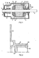
- Fig. 1 einen Längsschnitt durch einen Dauermagnet-Kommutatormotor,
- Fig. 2 einen vergrößerten Detailausschnitt aus Fig. 1 im Bereich der rechten Isolierendscheibe.
- Fig. 1 zeigt einen Dauermagnet-Kommutatormotor. An der Innenumfangsfläche des
Statorgehäuses 12 sind das Magnetfelderzeugende Dauermagnete 14 angeordnet. Stirnseitig sind amStatorgehäuse 12Lagerbügel 8,9 befestigt. DieLagerbügel 8, 9 nehmenKalottenlager 4, 5 auf, in denen eine Rotorwelle 2 drehbar gelagert ist. Auf die Rotorwelle 2 ist ein Rotorblechpaket 1 z.B. im Preßsitz gehalten. Auf dem linken Wellenende der Rotorwelle 2 ist innerhalb des Gehäuses ein Kommutator 10 aufgeklebt. Hammer-Bürstenhalter statorgehäusefesten Bürstenbrücke 17 gelagert und mit der äußeren Anschlußleitung verbunden. An die Lamellen des Kommutators 10 sind die Wicklungsenden der gewickelten Rotorwicklung angeschlossen, von der in Fig. 1 diestirnseitigen Wickelköpfe
- 1 shows a longitudinal section through a permanent magnet commutator motor,
- Fig. 2 shows an enlarged detail of FIG. 1 in the area of the right insulating washer.
- Fig. 1 shows a permanent magnet commutator motor.
Permanent magnets 14 which generate the magnetic field are arranged on the inner circumferential surface of thestator housing 12. 12 bearingbrackets 8, 9 are fastened to the end of the stator housing. Thebearing bracket 8, 9 accommodatespherical bearings 4, 5, in which a rotor shaft 2 is rotatably mounted. A rotor laminated core 1 is held on the rotor shaft 2, for example in a press fit. A commutator 10 is glued to the left shaft end of the rotor shaft 2 within the housing.Hammer brush holders brush bridge 17 fixed to the stator housing in a manner not shown here and are connected to the outer connecting line. The winding ends of the wound rotor winding are connected to the fins of the commutator 10, of which theend winding heads
Zur elektrischen Isolierung der Wickelköpfe 6, 7 gegenüber den Stirnseiten des Rotorblechpaketes 1 und gegenüber der Rotorwelle 2 sind Kunststoff-Isolierendscheiben 3, 13 mit je einem axial angeformten und zumindest im Bereich der Wickelköpfe die Rotorwelle 2 übergreifenden Kragen vorgesehen. Die rechte Isolierendscheibe 3 wird darüber hinaus nicht nur zur Isolierung der Wicklung gegenüber dem Rotorblechpaket 1 und der Rotorwelle 2 sondern in erfindungsgemäßer Weise auch zur Axialspieleinstellung mittels einer Distanzbuchse 32 mitbenutzt. Die Ausgestaltung der Isolierendscheibe 3 und insbesondere des an diese Isolierendscheibe 3 angeformten axialen Kragen sowie der in diesem Kragen erfindungsgemäß gehalterten Distanzbuchse 32 ist in dem Detailausschnittbild gemäß Fig. 2 deutlicher herausgestellt. Zur Typenvereinheitlichung ist an der linken Seite des Rotorblechpaketes 1 der gleiche Typ einer Isolierendscheibe benutzt, obwohl hier eine Distanzbuchse im vorliegenden Fall nicht vorgesehen ist.For the electrical insulation of the
Der axial angeformte Kragen 31 der Isolierendscheibe 3 weist eine zur Rotorwelle 2 konzentrische innere Ausnehmung 33 auf, in die die Distanzbuchse 32 eingepreßt ist. In vorteilhafter Weise ist vorgesehen, daß bei der Herstellung der Isolierendscheibe 3 gleichzeitig die Distanzbuchse 32 mitgefertigt und bereits durch Einpressen bis zu einer bestimmten axialen Tiefe in die Ausnehmung 33 im Sinne eines einheitlichen Bauteils vorgefügt ist.The axially formed
Zur Vergrößerung der Anlagefläche zwischen der Kalotte 4 und der Distanzbuchse 32 weist diese an ihrer der Kalotte 4 zugewandten Stirnseite eine radial überkragende Schulter 321 auf. Beim Aufdrücken der Isolierendscheibe 3 mit der vorgefügten Distanzbuchse 32 drückt das entsprechende Werkzeug gleichartig auf die Stirnseite der Isolierendscheibe 3 als auch der Distanzbuchse 32. Nach der Montage des Lagerbügels 8 kann ein eventuell zu geringes axiales Spiel durch bekannte, z.B. in der eingangs genannten Druckschrift beschriebene, Maßnahmen vergrößert werden.To enlarge the contact surface between the calotte 4 and the
Selbstverständlich ist darauf zu achten, daß beim Vorfügen die Distanzbuchse 32 nur so weit in die Ausnehmung 33 des Kragens 31 eingeschoben wird, daß die verbleibende Einschubstrecke zumindest so groß ist, daß bei der endgültigen Montage des Lagerbügels 8 an der rechten Stirnseite des Statorgehäuses 12 die Distanzbuchse 32 unter Berücksichtigung des gewünschten einzuhaltenden Axialspiels in die Ausnehmung 33 des Kragens 31 der Isolierendscheibe 3 eindrückbar ist.Of course, care must be taken that the
Im einzelnen ist ein erfindungsgemäß vorteilhaftes Verfahren des in Fig. 1 dargestellten Motors einschließlich der Einstellung des Axialspiels durch folgende wesentliche aufeinanderfolgende Montageschritte gekennzeichnet:
- a) Aufdrücken der-Isolierendscheibe mit der in der Ausnehmung unter Preßsitz vorgefügt gehaltenen Distanzbuchse über das eine Ende der Rotorwelle bis zum Anliegen der Isolierendscheibe an der einen Stirnseite des Blechpaketes; dabei liegt das Druckwerkzeug zweckmäßigerweise gleichzeitig sowohl an der Isolierendscheibe als auch an der Distanzbuchse an,
- b) nach Aufschieben einer Isolierendscheibe auf die andere Stirnseite-des Blechpaketes und gegebenenfalls nach Aufkleben eines Kommutators auf das über diese Stirnseite vorstehende andere Wellenende der Rotorwelle Bewickeln des Rotors,
- c) Einsetzen des bewickelten Rotors in das Lager des mit dem Stator verbundenen ersten Lagerbügels,
- d) Aufsetzen des zweiten Lagerbügels und dabei durch Axialdruck gleichzeitiges Verschieben der sowohl zur Rotorwelle als auch zum Kragen der Isolierendscheibe im Preßsitz gehaltenen Distanzbuchse,
- e) gegebenenfalls Feineinstellung des Axialspiels zwischen Distanzbuchse und Lager des zweiten Lagerbügels.
- a) pressing on the insulating disk with the spacer bush held in the recess under a press fit over one end of the rotor shaft until the insulating disk rests on one end face of the laminated core; the pressure tool expediently lies against both the insulating washer and the spacer at the same time,
- b) after sliding an insulating washer onto the other end face of the laminated core and, if necessary, after sticking a commutator onto the other shaft end of the rotor shaft protruding beyond this end face, winding the rotor,
- c) inserting the wound rotor into the bearing of the first bearing bracket connected to the stator,
- d) fitting the second bearing bracket and thereby simultaneously displacing the spacer bush, which is held in a press fit both to the rotor shaft and to the collar of the insulating disk, by axial pressure,
- e) if necessary, fine adjustment of the axial play between the spacer bush and the bearing of the second bearing bracket.
Claims (4)
Priority Applications (3)
| Application Number | Priority Date | Filing Date | Title |
|---|---|---|---|
| AT81104012T ATE12152T1 (en) | 1981-05-25 | 1981-05-25 | DEVICE AND PROCEDURE FOR ADJUSTING THE END PLAY BETWEEN THE ROTOR AND THE STATOR MOUNTED BEARINGS OF AN ELECTRIC MOTOR. |
| DE8181104012T DE3169239D1 (en) | 1981-05-25 | 1981-05-25 | Method and apparatus for adjusting the axial play between the rotor and the bearings fitted to the stator of an electric motor |
| EP81104012A EP0065585B2 (en) | 1981-05-25 | 1981-05-25 | Method for adjusting the axial play between the rotor and the bearings fitted to the stator of an electric motor. |
Applications Claiming Priority (1)
| Application Number | Priority Date | Filing Date | Title |
|---|---|---|---|
| EP81104012A EP0065585B2 (en) | 1981-05-25 | 1981-05-25 | Method for adjusting the axial play between the rotor and the bearings fitted to the stator of an electric motor. |
Publications (3)
| Publication Number | Publication Date |
|---|---|
| EP0065585A1 true EP0065585A1 (en) | 1982-12-01 |
| EP0065585B1 EP0065585B1 (en) | 1985-03-13 |
| EP0065585B2 EP0065585B2 (en) | 1991-04-17 |
Family
ID=8187735
Family Applications (1)
| Application Number | Title | Priority Date | Filing Date |
|---|---|---|---|
| EP81104012A Expired - Lifetime EP0065585B2 (en) | 1981-05-25 | 1981-05-25 | Method for adjusting the axial play between the rotor and the bearings fitted to the stator of an electric motor. |
Country Status (3)
| Country | Link |
|---|---|
| EP (1) | EP0065585B2 (en) |
| AT (1) | ATE12152T1 (en) |
| DE (1) | DE3169239D1 (en) |
Cited By (11)
| Publication number | Priority date | Publication date | Assignee | Title |
|---|---|---|---|---|
| EP0175798A1 (en) * | 1984-09-24 | 1986-04-02 | Siemens Aktiengesellschaft | Device and method to adjust the axial play between rotor and bearings fixed to the stator of an electric motor |
| EP0213427A1 (en) * | 1985-08-16 | 1987-03-11 | Siemens Aktiengesellschaft | Method for adjusting the axial play between the rotor and the stator of a motor |
| GB2184895A (en) * | 1985-12-23 | 1987-07-01 | Berger Gmbh & Co Gerhard | Retaining bearing guard plate relative to electric motor rotor |
| FR2606950A1 (en) * | 1986-11-15 | 1988-05-20 | Licentia Gmbh | PULLEY ELECTRIC MOTOR MOUNTED ON ROTOR SHAFT |
| DE3529483C1 (en) * | 1985-08-16 | 1989-06-29 | Siemens AG, 1000 Berlin und 8000 München | Method for adjusting the axial play between the rotor and stator of an electric motor |
| FR2626117A1 (en) * | 1988-01-14 | 1989-07-21 | Valeo | DEVICE AND METHOD FOR THE TIMING, FOLLOWING THE AXIAL DIRECTION, OF THE ROTOR OF A ROTATING MACHINE AND IN PARTICULAR OF AN ELECTRIC MOTOR, AND ROTATING MACHINE THUS CHECKED |
| US4899432A (en) * | 1985-09-26 | 1990-02-13 | Siemens Aktiengesellschaft | Method for adjusting the axial play between the rotor and a motor |
| EP0703656A1 (en) * | 1994-09-23 | 1996-03-27 | Siemens Aktiengesellschaft | Apparatus for adjusting the axial backlash between the rotor and the stator of a motor |
| US6707198B1 (en) | 1999-04-16 | 2004-03-16 | Black & Decker Inc. | Armature shaft retainer |
| DE102010062323A1 (en) | 2010-12-02 | 2012-06-06 | Robert Bosch Gmbh | Bearing arrangement for blower module of motor vehicle, has intermediate element which is fastened between sleeve bearings on shaft by frictional connection elements, and is extended over entire spacing of sleeve bearings |
| WO2012150242A3 (en) * | 2011-05-04 | 2013-07-25 | BSH Bosch und Siemens Hausgeräte GmbH | Axial bearing for an electric drive |
Families Citing this family (1)
| Publication number | Priority date | Publication date | Assignee | Title |
|---|---|---|---|---|
| DE102013220049A1 (en) * | 2013-10-02 | 2015-04-02 | Robert Bosch Gmbh | Electric machine and method for adjusting the axial bearing clearance |
Citations (5)
| Publication number | Priority date | Publication date | Assignee | Title |
|---|---|---|---|---|
| DE1838776U (en) * | 1961-06-09 | 1961-10-05 | Richard Stube | ANCHOR FOR SMALL ELECTRIC MOTORS. |
| DE1178934B (en) * | 1963-08-03 | 1964-10-01 | Heidolph Elektro K G | Adjustment of the axial play between the bearings in small electric motors |
| DE1987223U (en) * | 1968-06-12 | Licentia Patent-Verwaltungs-G.m.b.H., 6000 Frankfurt | Device for adjusting the axial play of the rotor of an electric motor | |
| DE1538921B2 (en) * | 1966-11-04 | 1970-04-02 | Licentia Patent-Verwaltungs-GmbH, 6OOO Prankfurt | Device for adjusting the axial play between the rotor and the stator of a motor mounted in plain bearings |
| DE1463968B2 (en) * | 1964-09-01 | 1971-11-18 | Licentia Patent-Verwaltungs-Gmbh, 6000 Frankfurt | SMALL ELECTRIC MOTOR |
-
1981
- 1981-05-25 AT AT81104012T patent/ATE12152T1/en not_active IP Right Cessation
- 1981-05-25 DE DE8181104012T patent/DE3169239D1/en not_active Expired
- 1981-05-25 EP EP81104012A patent/EP0065585B2/en not_active Expired - Lifetime
Patent Citations (5)
| Publication number | Priority date | Publication date | Assignee | Title |
|---|---|---|---|---|
| DE1987223U (en) * | 1968-06-12 | Licentia Patent-Verwaltungs-G.m.b.H., 6000 Frankfurt | Device for adjusting the axial play of the rotor of an electric motor | |
| DE1838776U (en) * | 1961-06-09 | 1961-10-05 | Richard Stube | ANCHOR FOR SMALL ELECTRIC MOTORS. |
| DE1178934B (en) * | 1963-08-03 | 1964-10-01 | Heidolph Elektro K G | Adjustment of the axial play between the bearings in small electric motors |
| DE1463968B2 (en) * | 1964-09-01 | 1971-11-18 | Licentia Patent-Verwaltungs-Gmbh, 6000 Frankfurt | SMALL ELECTRIC MOTOR |
| DE1538921B2 (en) * | 1966-11-04 | 1970-04-02 | Licentia Patent-Verwaltungs-GmbH, 6OOO Prankfurt | Device for adjusting the axial play between the rotor and the stator of a motor mounted in plain bearings |
Cited By (17)
| Publication number | Priority date | Publication date | Assignee | Title |
|---|---|---|---|---|
| US4888508A (en) * | 1984-09-24 | 1989-12-19 | Siemens Aktiengesellschaft | Device and procedure to adjust the axial play between the rotor and the stator mounted bearings of an electrical motor |
| EP0175798A1 (en) * | 1984-09-24 | 1986-04-02 | Siemens Aktiengesellschaft | Device and method to adjust the axial play between rotor and bearings fixed to the stator of an electric motor |
| EP0213427A1 (en) * | 1985-08-16 | 1987-03-11 | Siemens Aktiengesellschaft | Method for adjusting the axial play between the rotor and the stator of a motor |
| DE3529483C1 (en) * | 1985-08-16 | 1989-06-29 | Siemens AG, 1000 Berlin und 8000 München | Method for adjusting the axial play between the rotor and stator of an electric motor |
| US4899432A (en) * | 1985-09-26 | 1990-02-13 | Siemens Aktiengesellschaft | Method for adjusting the axial play between the rotor and a motor |
| GB2184895B (en) * | 1985-12-23 | 1990-06-06 | Berger Gmbh & Co Gerhard | Rotor for an electric motor |
| GB2184895A (en) * | 1985-12-23 | 1987-07-01 | Berger Gmbh & Co Gerhard | Retaining bearing guard plate relative to electric motor rotor |
| FR2606950A1 (en) * | 1986-11-15 | 1988-05-20 | Licentia Gmbh | PULLEY ELECTRIC MOTOR MOUNTED ON ROTOR SHAFT |
| FR2626117A1 (en) * | 1988-01-14 | 1989-07-21 | Valeo | DEVICE AND METHOD FOR THE TIMING, FOLLOWING THE AXIAL DIRECTION, OF THE ROTOR OF A ROTATING MACHINE AND IN PARTICULAR OF AN ELECTRIC MOTOR, AND ROTATING MACHINE THUS CHECKED |
| US4967111A (en) * | 1988-01-14 | 1990-10-30 | Valeo | System for axially locating the rotor of a rotating machine |
| EP0703656A1 (en) * | 1994-09-23 | 1996-03-27 | Siemens Aktiengesellschaft | Apparatus for adjusting the axial backlash between the rotor and the stator of a motor |
| US6707198B1 (en) | 1999-04-16 | 2004-03-16 | Black & Decker Inc. | Armature shaft retainer |
| DE102010062323A1 (en) | 2010-12-02 | 2012-06-06 | Robert Bosch Gmbh | Bearing arrangement for blower module of motor vehicle, has intermediate element which is fastened between sleeve bearings on shaft by frictional connection elements, and is extended over entire spacing of sleeve bearings |
| WO2012150242A3 (en) * | 2011-05-04 | 2013-07-25 | BSH Bosch und Siemens Hausgeräte GmbH | Axial bearing for an electric drive |
| CN103503284A (en) * | 2011-05-04 | 2014-01-08 | Bsh博世和西门子家用电器有限公司 | Axial bearing for an electric drive |
| CN103503284B (en) * | 2011-05-04 | 2016-10-05 | Bsh家用电器有限公司 | Cod for power-jdriven gear |
| US9702370B2 (en) | 2011-05-04 | 2017-07-11 | Bsh Hausgeraete Gmbh | Axial bearing for an electric drive |
Also Published As
| Publication number | Publication date |
|---|---|
| EP0065585B1 (en) | 1985-03-13 |
| ATE12152T1 (en) | 1985-03-15 |
| EP0065585B2 (en) | 1991-04-17 |
| DE3169239D1 (en) | 1985-04-18 |
Similar Documents
| Publication | Publication Date | Title |
|---|---|---|
| EP0065585B1 (en) | Method for adjusting the axial play between the rotor and the bearings fitted to the stator of an electric motor. | |
| EP0222107B1 (en) | Method for adjusting the end play between the rotor and the stator of an electric motor | |
| EP0175798B1 (en) | Device and method to adjust the axial play between rotor and bearings fixed to the stator of an electric motor | |
| EP2556582B1 (en) | Rotor | |
| CH648706A5 (en) | COLLECTORLESS DC MOTOR. | |
| DE1488656A1 (en) | Method for assembling rotating electrical machines using the magnet molding method | |
| DE10261434A1 (en) | Insulated stator core with attachment features | |
| WO1998037613A1 (en) | Rotor and method for producing same | |
| EP0260570B1 (en) | Process of manufacturing a commutator motor with an insulating covering of the rotor shaft | |
| WO2020216594A1 (en) | Stator of an electrical machine having a replaceable temperature sensor | |
| DE1763613A1 (en) | Method for assembling rotating electrical machines | |
| DE2056640A1 (en) | Method and device for manufacturing a stator for electric motors or other electric machines | |
| DE2550640A1 (en) | STATOR FOR ELECTRIC MACHINERY | |
| DE4432356A1 (en) | Assembly process for electric motor rotor shaft | |
| EP3093960A1 (en) | Rotor with a ring magnet and a plastic part | |
| DE3222478A1 (en) | ROTOR FOR A SUPRAL-CONDUCTING ELECTRIC ROTATION MACHINE | |
| DE102019001273B4 (en) | Stator of an electric motor, electric motor and method for producing a stator | |
| DE69934291T2 (en) | stepper motor | |
| DE8115518U1 (en) | DEVICE FOR ADJUSTING THE AXIAL CLEARANCE BETWEEN THE ROTOR AND THE STORAGE OF AN ELECTRIC MOTOR ATTACHED TO THE STATOR | |
| EP0703656B1 (en) | Apparatus for adjusting the axial backlash between the rotor and the stator of a motor | |
| EP0213427B1 (en) | Method for adjusting the axial play between the rotor and the stator of a motor | |
| WO2023051861A1 (en) | Laminated electrical steel core for an electric machine and method for producing a laminated electrical steel core | |
| DE102017202546A1 (en) | Stator of an electric motor and electric motor | |
| DE102022134047B4 (en) | Stator and electric motor and method for producing a stator | |
| WO2003088450A1 (en) | Rotor for an electric machine |
Legal Events
| Date | Code | Title | Description |
|---|---|---|---|
| PUAI | Public reference made under article 153(3) epc to a published international application that has entered the european phase |
Free format text: ORIGINAL CODE: 0009012 |
|
| 17P | Request for examination filed |
Effective date: 19811028 |
|
| AK | Designated contracting states |
Designated state(s): AT DE FR GB IT |
|
| ITF | It: translation for a ep patent filed | ||
| GRAA | (expected) grant |
Free format text: ORIGINAL CODE: 0009210 |
|
| AK | Designated contracting states |
Designated state(s): AT DE FR GB IT |
|
| REF | Corresponds to: |
Ref document number: 12152 Country of ref document: AT Date of ref document: 19850315 Kind code of ref document: T |
|
| REF | Corresponds to: |
Ref document number: 3169239 Country of ref document: DE Date of ref document: 19850418 |
|
| ET | Fr: translation filed | ||
| PLBI | Opposition filed |
Free format text: ORIGINAL CODE: 0009260 |
|
| 26 | Opposition filed |
Opponent name: AEG AKTIENGESELLSCHAFT, BERLIN UND FRANKFURT Effective date: 19851130 |
|
| PGFP | Annual fee paid to national office [announced via postgrant information from national office to epo] |
Ref country code: AT Payment date: 19890503 Year of fee payment: 9 |
|
| PG25 | Lapsed in a contracting state [announced via postgrant information from national office to epo] |
Ref country code: AT Effective date: 19900525 |
|
| PUAH | Patent maintained in amended form |
Free format text: ORIGINAL CODE: 0009272 |
|
| STAA | Information on the status of an ep patent application or granted ep patent |
Free format text: STATUS: PATENT MAINTAINED AS AMENDED |
|
| 27A | Patent maintained in amended form |
Effective date: 19910417 |
|
| AK | Designated contracting states |
Kind code of ref document: B2 Designated state(s): AT DE FR GB IT |
|
| ITTA | It: last paid annual fee | ||
| ET3 | Fr: translation filed ** decision concerning opposition | ||
| ITF | It: translation for a ep patent filed | ||
| PGFP | Annual fee paid to national office [announced via postgrant information from national office to epo] |
Ref country code: GB Payment date: 19970418 Year of fee payment: 17 |
|
| PG25 | Lapsed in a contracting state [announced via postgrant information from national office to epo] |
Ref country code: GB Free format text: LAPSE BECAUSE OF NON-PAYMENT OF DUE FEES Effective date: 19980525 |
|
| GBPC | Gb: european patent ceased through non-payment of renewal fee |
Effective date: 19980525 |
|
| PGFP | Annual fee paid to national office [announced via postgrant information from national office to epo] |
Ref country code: FR Payment date: 20000523 Year of fee payment: 20 |
|
| PGFP | Annual fee paid to national office [announced via postgrant information from national office to epo] |
Ref country code: DE Payment date: 20000717 Year of fee payment: 20 |